Sign In
Upload
Manuals
Brands
Teledyne Manuals
Analytical Instruments
3220
Teledyne 3220 Manuals
Manuals and User Guides for Teledyne 3220. We have
1
Teledyne 3220 manual available for free PDF download: Instruction Manual
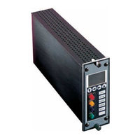
Teledyne 3220 Instruction Manual (58 pages)
Oxygen Monitor System
Brand:
Teledyne
| Category:
Analytical Instruments
| Size: 0.81 MB
Table of Contents
Important Notice
6
Safety Checklist
6
Safety Messages
7
Table of Contents
9
Table of Contents
12
List of Figures
12
List of Tables
15
Introduction
15
Overview
15
Description
15
Figure 1-1: Model 3220 System
15
System Chassis (19" Rack)
16
Control Unit
16
Channel Modules
16
Main Features of the Channel Module
16
Figure 1-2: Control Unit
16
Figure 1-3: the Channel Module
17
Remote Probe Assemblies
18
Operational Theory
20
Introduction
20
System Chassis
20
Control Unit
20
Figure 2-1: Control Unit Front Panel
21
Figure 2-2: Control Unit Block Diagram
21
Channel Module
22
Figure 2-3: Block Diagram of the Signal Processing Electronics
23
Micro-Fuel Cell
24
Anatomy of a Micro-Fuel Cell
24
Figure 2-4: Micro-Fuel Cell
24
Figure 2-5: Cross Section of a Micro-Fuel Cell
25
Electrochemical Reactions
26
The Effect of Pressure
26
Calibration Characteristics
27
Figure 2-6: Characteristic Input/Output Curve for MFC
27
Micro-Fuel Cell "Class
28
Class A-3 Cell
28
Class A-5 Cell
28
Class B-1 Cell
28
Model
28
Class B-3 Cell
28
Class C-3 Cell
29
Hydrogen And/Or Helium Service
29
Installation
30
Unpacking the Analyzer
30
System Chassis
30
Location
30
Power
30
Electrical Connections
31
Probe Assemblies
31
Micro-Fuel Cell
32
Figure 3-1: Oxygen Probe Assembly
32
Control Unit
33
Control Unit Fuses
33
Control Unit Jumper Settings
34
Table 3-1: Control Unit Jumper Configuration
34
Table 3-2: Fail-Safe/Non Fail-Safe Alarm Configuration
34
Table 3-3: External Alarm-Failsafe/Non-Failsafe Configuration
35
Table 3-4: External Alarm-Contact Closure
35
Table 3-5: External Alarm-Line Voltage to External Connection
35
Channel Modules
36
Removing the Channel Module Cover
36
Changing the Fuse
36
Configuring the Internal Jumper Connections
37
Figure 3-2: Fuse Location
37
Table 3-6: Channel Module Internal Jumper Settings
37
Table 3-7: RS-485 Jumper Settings
38
Table 3-8: Jumper Settings for Channel Module Output
38
Operation
39
Introduction
39
Control Unit Operation
39
System Power Switch and LED
39
Audible Alarm Switch and Bypass LED
39
Fuses
40
RS485 Port
40
Channel Module Front Panel Controls and Indicators
40
Figure 4-1: RS-485 Port on Control Unit
40
Figure 4-2: Display Panel Configuration
43
Calibration Procedures
44
Zero Calibrating a Single Sensor Channel Module
44
Span Calibrating a Channel Module
45
Using the "1MAN" Calibration Option
45
Zero and Span Calibrating a Channel Module
45
Alarm Configuration Procedures
46
Defining the Setpoint for Alarm 1 and Alarm
46
Configuring Alarm Relay Settings
47
Setting the Fail-Safe or Non-Fail-Safe Mode
47
Setting the Latching or Non-Latching Mode
47
Setting Alarms to Hi or lo
48
Setting the ID Code
48
Enabling/Disabling the Pass Code
49
Range Set-Up
50
Routine Operation
50
Cell Failure Set-Up
51
FAIL Alarm Conditions
51
Failure and Error Codes
52
Error Codes
52
Appendix
54
Specifications
54
Recommended Spare Parts List
55
Drawing List
56
Index
57
Advertisement
Advertisement
Related Products
Teledyne 327RBCEU
Teledyne 327RACEU
Teledyne 327RBEU
Teledyne 327RAEU
Teledyne 327
Teledyne 326
Teledyne 328
Teledyne 3290
Teledyne 3010MA
Teledyne 3010PA
Teledyne Categories
Measuring Instruments
Analytical Instruments
Digital Camera
Test Equipment
Security Camera
More Teledyne Manuals
Login
Sign In
OR
Sign in with Facebook
Sign in with Google
Upload manual
Upload from disk
Upload from URL