Subaru 1997 Impreza Manuals
Manuals and User Guides for Subaru 1997 Impreza. We have 2 Subaru 1997 Impreza manuals available for free PDF download: Service Manual
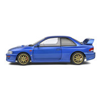
Subaru 1997 Impreza Service Manual (616 pages)
Brand: Subaru
|
Category: Automobile
|
Size: 45.57 MB
Table of Contents
-
Capacity6
-
Weight7
-
Brake Test10
-
Towing11
-
Lubricants20
-
Fluid21
-
Coolant21
-
Sealants22
-
Adhesives22
-
Garage Jack24
-
Fuel Cap89
-
Canister90
-
Timing Belt96
-
Belt Cover98
-
Camshaft99
-
Cylinder Head100
-
Cylinder Block101
-
Crankshaft101
-
Piston102
-
Cooling Lines104
-
Mechanical Seal106
-
Thermostat107
-
Radiator Fan108
-
Air Line116
-
Throttle Body116
-
Fuel Line119
-
Fuel Injector120
-
Intercooler126
-
Pressure Sensor127
-
Oxygen Sensor129
-
Knock Sensor133
-
Control System134
-
Idle Air Control142
-
A/C Cut Control144
-
Fuel Pump150
-
Fuel Filter151
-
Read Memory Mode168
-
D-Check Mode169
-
Check Main Relay173
-
LHD Diagram177
-
RHD Diagram177
-
With Immobillser184
-
Off210
-
Clutch Outline235
-
Clutch Operation236
-
AWD System247
-
Wheels and Axles253
-
AWD Turbo Model255
-
Rear Drive Shaft256
-
Steering System257
-
Hydraulic System259
-
Gearbox Assembly260
-
Power Cylinder260
-
Control Valve261
-
Vane Pump266
-
Brakes271
-
Disc Brake271
-
Master Cylinder272
-
Brake Booster273
-
ABS Sensor285
-
G Sensor288
-
Pre-Inspection299
-
Inspection Mode310
-
Clearing Memory311
-
Check Generator318
-
Check Relay Box319
-
Check ABS Sensor329
-
Check Hub Runout332
-
Check ABSCM333
-
Check TCM371
-
Check at371
-
Check Sensor374
Advertisement
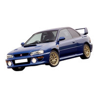
Subaru 1997 Impreza Service Manual (616 pages)
Brand: Subaru
|
Category: Automobile
|
Size: 177.62 MB
Table of Contents
-
Weight7
-
Brake Test10
-
Towing11
-
Fuel19
-
Lubricants20
-
Fluid21
-
Coolant21
-
Sealants22
-
Adhesives22
-
Garage Jack24
-
Lift26
-
Safety Stand26
-
Hill-Holder68
-
Gearbox71
-
Tie-Rod72
-
Fuel Cap89
-
Canister90
-
Timing Belt96
-
Belt Cover98
-
Camshaft99
-
Cylinder Head100
-
Cylinder Block101
-
Crankshaft101
-
Piston102
-
Cooling Lines104
-
Mechanical Seal106
-
Thermostat107
-
Air Line General116
-
Throttle Body116
-
Fuel Injector120
-
Intercooler126
-
Pressure Sensor127
-
Oxygen Sensor129
-
Knock Sensor133
-
Idle Air Control142
-
A/C Cut Control144
-
Fuel Pump150
-
Fuel Filter151
-
Pre-Inspection154
-
Power Supply154
-
Caps and Plugs154
-
Fuel Pressure155
-
Engine Grounding155
-
Module and Relay159
-
Schematic161
-
Read Memory Mode168
-
D-Check Mode169
-
Check Main Relay173
-
Starter Switch193
-
Clutch Outline235
-
Clutch Operation236
-
Front Suspension251
-
Rear Suspension252
-
AWD Turbo Model255
-
Rear Drive Shaft256
-
Tilt Mechanism257
-
Hydraulic System259
-
Gearbox Assembly260
-
Power Cylinder260
-
Control Valve261
-
Oil Pump & Tank265
-
Vane Pump266
-
Disc Brake271
-
Master Cylinder272
-
Brake Booster273
-
ABS Sensor285
-
G Sensor288
-
Brakes297
-
Brakes Schematic302
-
Inspection Mode310
-
Trouble Codes310
-
Clearing Memory311
-
Check Generator318
-
Check Relay Box319
-
Check ABS Sensor329
-
Check Hub Runout332
-
Check ABSCM333
Advertisement