Sign In
Upload
Manuals
Brands
Siemens Manuals
Computer Hardware
SIMATIC S7-400 CP 440
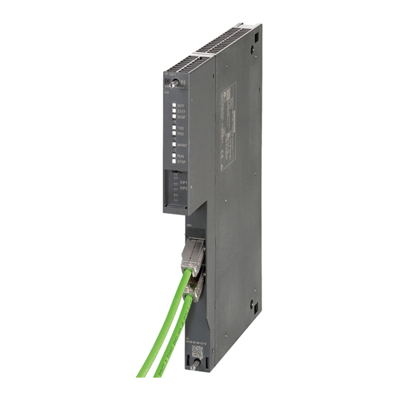
Siemens SIMATIC S7-400 CP 440 Manuals
Manuals and User Guides for Siemens SIMATIC S7-400 CP 440. We have
1
Siemens SIMATIC S7-400 CP 440 manual available for free PDF download: Installation And Parameter Assignment
Siemens SIMATIC S7-400 CP 440 Installation And Parameter Assignment (156 pages)
Point-to-point connection
Brand:
Siemens
| Category:
Computer Hardware
| Size: 2.15 MB
Table of Contents
Preface
3
Table of Contents
7
1 Product Description
13
Uses of the CP 440
13
Table 1-1 Functions of the CP 440
14
Components Required for a Point-To-Point Connection with the CP 440
15
Required Hardware Components
15
Table 1-2 Hardware Components for a Point-To-Point Connection with the CP 440
15
Required Software Components
16
Incompatible CPU Versions
16
Table 1-3 Software Components for a Point-To-Point Connection with the CP 440
16
Table 1-4 CPU Versions with Which the CP 440 Can be Used as of the Version Indicated
16
Table 1-5 CPU Versions with Which the CP 440 Cannot be Used
17
Design of the CP 440
18
Figure 1-1 Arrangement of the Controls and Indicators on the CP 440 Communication Processor
18
Features of the X27 (RS 422/485) Interface
20
2 Basic Principles of Serial Data Transmission
21
Serial Transmission of a Character
21
Figure 2-1 10-Bit Character Frame
23
Figure 2-2 Character Delay Time
24
Transmission Procedure with a Point-To-Point Connection
25
Transmission Integrity
27
Figure 2-3 Position of the Supplied Protocols of the CP 440 in the Reference Model
27
Data Transmission with the ASCII Driver
30
Sending Data with the ASCII Driver
31
Figure 2-4 Sequence of a Send Operation
32
Receiving Data with the ASCII Driver
33
Figure 2-5 Sequence of Receive Operation with End Criterion "Expiration of Character Delay Time
34
Figure 2-6 Sequence of Receive Operation with "End-Of-Text Character" End Criterion
36
Figure 2-7 Sequence of Receive Operation with "Fixed Message Frame Length" End Criterion
38
Topologies between the Communication Partners
40
Figure 2-8 RS 422 Point-To-Point
40
Figure 2-9 RS 485 Point-To-Point
40
Figure 2-10 RS 422 Multipoint
41
Figure 2-11 RS 485 Multipoint
42
Data Transmission with the 3964(R) Procedure
43
The Control Characters of the 3964(R) Procedure
43
Block Checksum
44
Figure 2-12 Block Checksum
44
Sending Data with 3964(R)
45
Figure 2-13 Data Traffic When Sending with the 3964(R) Procedure
45
Figure 2-14 Flow Diagram of Sending with the 3964(R) Procedure
47
Receiving Data with 3964(R)
48
Figure 2-15 Data Traffic When Receiving with the 3964(R) Procedure
48
Figure 2-16 Flow Diagram of Receiving with the 3964(R) Procedure (Part 1)
50
Figure 2-17 Flow Diagram of Receiving with the 3964(R) Procedure (Part 2)
51
Handling Corrupt Data
53
Figure 2-18 Data Traffic When Receiving Corrupt Data
53
Figure 2-19 Data Traffic During an Initialization Conflict
54
Figure 2-20 Flow Diagram of the Startup of the 3964(R) Procedure
55
3 Commissioning the CP 440
57
4 Mounting the CP 440
61
CP 440 Slots
61
Mounting and Dismounting the CP 440
62
Installation Steps
62
Removal Steps
63
5 Configuring and Parameter Assignment the CP 440
65
Assigning Parameters to the CP 440
65
Table 5-1 Configuration Options for the CP 440
65
Installing the Programming Interface
66
Parameters for the Communications Protocols
67
Configuration Data
68
Introduction
68
Basic Parameters of the CP 440
68
Table 5-2 Basic Parameters of the CP 440
68
Table 5-3 Control of Message Frame Storage Without Flow Control
68
Table 5-4 Control of Frame Storage with Flow Control
69
Configuration Data of the ASCII Driver
70
Table 5-5 Protocol Parameters (ASCII Driver)
70
Table 5-6 Baud Rate / Character Frame (ASCII Driver)
72
Table 5-7 Data Flow Control (ASCII Driver)
73
Table 5-8 Receive Buffer on CP (ASCII Driver)
73
Table 5-9 X27 (RS 422/485) Interface (ASCII Driver)
74
Figure 5-1 Wiring of the Recipient at the X27 (RS 422/485) Interface (ASCII Driver)
75
Configuration Data of the 3964(R) Procedure
76
Table 5-10 3964(R) Protocol
76
Table 5-11 Protocol Parameters (3964(R) Procedure)
77
Table 5-12 Baud Rate / Character Frame (3964(R) Procedure)
78
Table 5-13 Receive Buffer on CP (3964(R) Procedure)
79
Table 5-14 X27 (RS 422) Interface (3964(R) Procedure)
79
Figure 5-2 Wiring of the Recipient at the X27 (RS 422) Interface (3964(R) Procedure)
80
Managing the Parameter Data
81
Firmware Updates
82
Subsequent Loading of Firmware Updates
82
Viewing the Firmware Version
84
Table 5-15 Leds for Firmware Update
84
6 Communication Via Function Blocks
85
Overview of the Function Blocks
86
Table 6-1 Function Blocks of the CP 440
86
Notes on Program Structure
88
Using the Function Blocks
89
S7 Transmits Data to a Communication Partner, 10 SEND_440 FB
90
Table 6-2 Block Call
91
Table 6-3 Parameters of the SEND_440 FB
92
Figure 6-1 Time Sequence Chart for the 10 SEND_440 FB
93
S7 Receives Data from a Communication Partner, 9 RECV_440 FB
94
Table 6-4 Block Call
95
Table 6-5 Parameters of the RECV_440 FB
96
Figure 6-2 Time Sequence Chart for the 9 RECV_440 FB
97
Deleting the Receive Buffer (11 "RES_RECV" FB)
98
Table 6-6 Block Call
98
Table 6-7 Parameters of the RES_RECV FB
99
Figure 6-3 Time Sequence Chart for the 11 RES_RECV FB
100
Programming the Function Blocks
101
General Information on Data Block Assignment
101
Figure 6-4 Contrasting Data Addressing in STEP 5 and STEP 7
101
Supplying the Block Parameters
103
General Information on Program Processing
107
Technical Specifications of the Function Blocks
108
Table 6-8 Memory Requirements of the Function Blocks (in Bytes)
108
Table 6-9 Run Times of the Function Blocks in Ms
108
Table 6-10 Minimum Number of CPU Cycles
109
7 Startup Characteristics and Operating Mode Transitions of the CP 440
111
Operating Modes of the CP 440
111
Startup Characteristics of the CP 440
112
Behavior of the CP 440 on Operating Mode Transitions of the CPU
113
Behavior of the Sender Line Drivers of the Serial Interface During Particular Operating Modes of the CP
114
Table 7-1 Behavior of the Sender Line Drivers
114
8 Diagnostics with the CP 440
115
Diagnostics Functions of the CP 440
115
Diagnostics Via the Display Elements of the CP 440
116
Table 8-1 Error Messages of the CP 440 Display Elements
116
Diagnostics Messages of the Function Blocks
117
Figure 8-1 Structure of the STATUS Parameter
117
Example: Structure of the STATUS Parameter for the Event "Request Aborted Due to Complete Restart, Figure 8-2 Restart or Reset
117
Table 8-2 Event Classes and Event Numbers
118
Table 8-3 Event Class 30
124
Diagnostics Via the Diagnostic Buffer of the CP 440
125
9 Programming Example for Standard Function Blocks
127
General Information
127
Device Configuration
128
Settings
128
Blocks Used
129
Table 9-1 CP 440 SEND RECV
129
Installation, Error Messages
132
Activation, Startup Program and Cyclic Program
133
CP440 SEND RECV" Program Example
133
CP440 1 CYC" Program Example
134
CP440 ASCII BCC" Program Example
135
CP440 MASTER" Program Example
136
CP440 SLAVE" Program Example
136
Technical Specifications
137
Technical Specifications of the CP
137
Cables
143
X27 (RS 422/485) Interface of the CP 440
143
Wire)
145
(Two-Wire)
146
Figure B-3 X27 Cable CP 440 - CP 544, CP 524, CPU 928B, CPU 945, CPU 948 for RS
147
Operation (Four-Wire Mode)
147
C Accessories and Order Numbers
149
Accessories and Order Numbers
149
D Literature
151
Literature on SIMATIC S7
151
Index
153
Advertisement
Advertisement
Related Products
Siemens Simatic S7-400
Siemens SIMATIC S7 400
Siemens Simatic S7-300 31xC Series
Siemens Simatic S7-300 CP 341
Siemens SIMATIC S7-1200 CP 1243-8 IRC
Siemens Simatic S7-300 314C-2 PN/DP
Siemens SENTRON PROFIBUS DPV1 Series
Siemens SMP16-CPU065
Siemens SMP16-CPU06 Series
Siemens SIMATIC NET CP 443-5 Extended
Siemens Categories
Industrial Equipment
Controller
Control Unit
Oven
Washer
More Siemens Manuals
Login
Sign In
OR
Sign in with Facebook
Sign in with Google
Upload manual
Upload from disk
Upload from URL