Sign In
Upload
Manuals
Brands
Siemens Manuals
Control Systems
SIDOOR ATD410W
Siemens SIDOOR ATD410W Manuals
Manuals and User Guides for Siemens SIDOOR ATD410W. We have
2
Siemens SIDOOR ATD410W manuals available for free PDF download: System Manual, Operating Instructions Manual
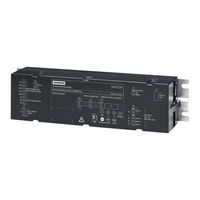
Siemens SIDOOR ATD410W System Manual (320 pages)
ATD4xxW Series, Door Control Systems for Industrial applications
Brand:
Siemens
| Category:
Control Systems
| Size: 7.31 MB
Table of Contents
Preface
4
Table of Contents
6
1 Sign Posts
12
2 System Overview
14
SIDOOR Door Control Systems
14
System Configuration and Area of Application
16
Products
18
Controllers
18
Geared Motors
19
Power Supply
20
Accessories
21
Optional Additional Units
24
Software
25
3 SIDOOR Functions
26
Basic Functions
29
Learn Run
29
Force Limit for Learn Run
37
Output Transmission
38
Drive Orders
39
DOOR CLOSE (Command Given Via Digital Inputs)
43
DOOR OPEN (Command Given Via Digital Inputs)
44
Stopping
45
Partial Opening
45
Obstruction Detection CLOSE
46
Obstruction Detection OPEN
46
Force and Energy Profiles (NDG Mode)
47
Slow Driving Curve Profile
48
DCOPS (Door Closed/Opened Position Sensor)
49
System Functions
51
Restart after Power Failure
51
Initial Run/Reference Run (Power ON)
52
Overload Protection of the Geared Motor
52
Vandalism Protection/Continuous Door Monitoring
53
Belt Break Monitoring
54
Friction Compensation
55
Oscillation Protection
56
Automatic Energy Limitation
57
External Closing Force
60
Synchronization of the Door Position
60
Cyclic Process Values Via Fieldbus
61
Extended Functions
62
Impulsedrive
62
Automatic Impulsedrive
64
Impulsestop
65
Automatic Impulsestop
66
Assisteddrive
67
Automatic Assisteddrive
69
Positioning Mode
70
Obstruction Detection
71
Obstruction Detection Process
72
Overcome Obstruction
72
Reversing (Retraction Attempt)
73
Combination of Retry and Reverse
74
Slow Obstruction Approach
74
Wait Mode
74
Expert Configuration
75
Free Function Blocks (FBLOCK)
76
Overview
76
Configuring the Logic
78
Digital and Logical Input Signals
80
Control Bits
81
Special Function Blocks
81
Discrepancy Analysis Blocks
81
Basic Blocks
81
Frequency Analysis Blocks
82
On Delay Block
82
Counter Block
83
Basic Parameter Editor (as of V1.10)
83
3.4 Safety Functions
85
Optional Safety Equipment
85
Light Barrier
85
Type 2 ESPE
87
Pressure-Sensitive Edge (SR)
89
Security Policy
90
Safe Force Output
90
Safe Speed Observance (Energy Limiting)
90
Safe Input Signals According to Pld
91
Internal Signal Routing
91
Redundant Antivalent Signal Logic with Discrepancy Analysis
92
Frequency-Based Input Signals
93
Two-Hand Operation Concept (According to Cat. IIIA)
94
Emergency Stop Concept in Accordance with Stop Category 1
96
Concept of Fail-Safe Digital Control (Door OPEN/CLOSE) with Emergency Stop Via 4
98
Digital Inputs
98
Concept of Fail-Safe Digital Control (Door OPEN/CLOSE) with Emergency Stop Via 3
101
Digital Inputs
101
4 Controllers
103
Description of Controller
103
Installing the Control Unit
104
Wiring Instructions
107
Connecting Terminals
108
Digital Input Signals
108
Voltage Output
111
Relay and Fieldbus Interfaces
112
Relay Module
112
Uss
116
USS Module
116
Wiring and Connecting the USS Plug
118
Wiring and Connecting Relay Outputs
120
Profibus
121
PROFIBUS Module
121
Wiring and Connecting PROFIBUS Connectors
125
Wiring and Connecting Relay Outputs
127
PROFIBUS Communication
129
Profinet
134
PROFINET Module
134
Wiring and Connecting a PROFINET Connector
141
Wiring and Connecting Relay Outputs
142
PROFINET Communication
144
Local/Master Operation
148
Master Monitoring
148
Sequential Control
149
Sensors and External Sensor Interface Module
152
Overview
152
Sensor Function Test
155
Reaction Times
156
Stopping Distances
156
Technical Specifications
157
Operation and Configuration of the Control Unit
161
Service Buttons
161
Operation Using Service Buttons
162
Parameter Assignment Via the Terminal Module
165
Parameter Assignment Using Additional Devices
167
Parameter Names
167
Adjustable Parameters
169
Driving Curve
169
Forces
170
Parameter Assignment
174
Parameter Assignment for Special Applications
188
5 Geared Motors
189
Description
189
Installation
190
Connecting Terminals
195
Conductor Assignment of the Motor Plug
195
Technical Specifications
196
Dimension Drawing of SIDOOR M3 with Rubber-Metal Anti-Vibration Mount and Mounting Bracket
205
Dimension Drawing of SIDOOR MDG180 with Rubber-Metal Anti-Vibration Mount and Mounting Bracket
206
Dimension Drawing of SIDOOR M4 with Rubber-Metal Anti-Vibration Mount and Mounting Bracket
207
Dimension Drawing of SIDOOR MDG400 with Rubber-Metal Anti-Vibration Mount and Mounting Bracket
208
Dimension Drawing MDG400NMS
209
Dimension Drawing of SIDOOR MDG400 NMS with Rubber-Metal Anti-Vibration Mount and Mounting Bracket
210
Dimension Drawing of SIDOOR M5
211
Dimension Drawing of SIDOOR MDG700 NMS
212
Dimension Drawing of MDG Motor Cable
213
Dimension Drawing of Motor Cable MDG2
214
Dimension Drawing of Deflector Pulley with Tensioning Device and Mounting Bracket
215
Dimension Drawing of Door Clutch Holder
216
6 Power Supply
217
Sidoor Nt40
217
Description
217
Installation
219
Connecting Terminals
220
Technical Specifications
222
SIDOOR Transformer
225
Description
225
Installation
226
Connecting Terminals
227
Technical Specifications
228
SITOP PSU8200 13A/36V 3-Phase
231
Power Supply Requirements of SITOP PSU8200
232
Installation
232
Technical Specifications
233
Building DC Voltage Supply
236
Power Supply Requirements
237
Installation
239
Uninterruptible Power Supply (UPS)
239
7 SIDOOR Service Tool
243
Description
243
Connection
243
Operation
244
Navigation Structure in the SIDOOR Service Tool
246
Technical Specifications
253
8 Configuration and Programming in STEP 7
254
PROFINET Integration Via GSD File
254
PROFIBUS Integration Via GSD File
255
Programming SIDOOR Instructions
256
Sidoor_Cdat" Data Type
257
Sidoor_Sdat" Data Type
258
9 Connecting and Commissioning
259
Overview of Safety and Commissioning
259
Preparing the Control Unit
263
Connecting a Geared Motor to the Control Unit
264
Connecting the Power Supply to the Network and Executing a Learn Run
266
Connecting Digital Inputs
267
Commissioning the Control Unit on the Fieldbus
268
Final Settings and Checks
271
10 Diagnostic and Maintenance
273
Operating State Display
273
Fault Management
274
Maintenance
275
Appendices
276
Structure of User Data/Process Data
276
A.1 Structure of User Data/Process Data
276
Parameter Interface
277
A.1.1 Parameter Interface
277
Parameter ID (PKE)
278
A.1.1.1 Parameter ID (PKE)
278
Parameter Index (IND)
281
Parameter Value (PWE)
283
Parameter ID
284
Parameter Description (PBE)
284
A.1.1.4 Parameter ID
284
Process Data
285
A.1.2 Process Data
285
STW1 - Control Word (Ctrlw)
286
TSW0 - Technology Control Word 0
287
TSW1 - Technology Control Word 1
287
TSW2 - Technology Control Word 2
289
ZSW1 - Status Word (Statw)
290
TZW0 - Technology Status Word 0
292
TZW1 - Technology Status Word 1
292
TZW2 - Technology Status Word 2
295
TZW3, TZW4, TZW5 - Technology Status Words 3, 4, 5
297
Profiles and Adjustment Ranges
299
Profile Name
299
Sidoor M3 L / R
299
Sidoor Mdg180 L / R
301
Sidoor M4 L / R
301
A.2.3 Sidoor Mdg180 L / R
301
Sidoor Mdg400 L / R
302
A.2.5 Sidoor Mdg400 L / R
302
Sidoor Mdg400Nms L / R
303
A.2.6 Sidoor Mdg400Nms L / R
303
Sidoor M5 L / R
305
Sidoor Mdg700Nms L / R
307
A.2.8 Sidoor Mdg700Nms L / R
307
Configuration Record
309
A.3 Configuration Record
309
Standards, Directives and Laws
311
Safety
311
Emc
312
Communications
312
A.4.2 Emc
312
Application-Specific Standards
313
Protective Devices
314
A.4.5 Protective Devices
314
Service & Support
316
A.5 Service & Support
316
Index
317
Advertisement
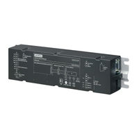
Siemens SIDOOR ATD410W Operating Instructions Manual (26 pages)
Controllers for protective machine door
Brand:
Siemens
| Category:
IP Access Controllers
| Size: 2.43 MB
Advertisement
Related Products
Siemens SIDOOR ATD401W
Siemens SIDOOR ATD420W
Siemens SIDOOR ATD430W
Siemens SICAM AK 3
Siemens ACC AP
Siemens ACC-APM-1220
Siemens ACC-APM-2420
Siemens SIDOOR
Siemens SIDOOR ATD400V
Siemens SIDOOR ATD400K
Siemens Categories
Industrial Equipment
Controller
Control Unit
Oven
Washer
More Siemens Manuals
Login
Sign In
OR
Sign in with Facebook
Sign in with Google
Upload manual
Upload from disk
Upload from URL