Seagate RealStor 4005 Series Manuals
Manuals and User Guides for Seagate RealStor 4005 Series. We have 3 Seagate RealStor 4005 Series manuals available for free PDF download: Hardware Installation And Maintenance Manual, Hardware Installation, Getting Started
Seagate RealStor 4005 Series Hardware Installation And Maintenance Manual (150 pages)
Table of Contents
-
Introduction12
-
-
Cache19
-
Compactflash19
-
-
-
-
Installation
50 -
Operation
79 -
-
Overview82
-
Leds82
-
-
PSU Leds86
-
Drawer Leds87
-
DDIC Led88
-
IOM Leds89
-
-
Host I/O94
-
-
Firmware Updates101
-
-
-
Overview107
-
ESD Precautions107
-
-
Removing a PCM108
-
Installing a PCM110
-
-
Removing an IOM120
-
-
Before You Begin122
-
-
-
Opening a Drawer126
-
-
-
Closing a Drawer127
-
Replacing a DDIC127
-
Removing a DDIC127
-
-
-
-
-
Preparation129
-
-
Replacing a PSU130
-
Removing a PSU130
-
Installing a PSU132
-
-
Replacing an FCM132
-
Removing an FCM132
-
-
Replacing an IOM133
-
Removing an IOM134
-
-
-
-
Before You Begin136
-
-
-
Index
149
Advertisement
Seagate RealStor 4005 Series Hardware Installation (107 pages)
Brand: Seagate
|
Category: Computer Hardware
|
Size: 8.25 MB
Table of Contents
-
Introduction10
-
Operation14
-
Cache16
-
Compactflash16
-
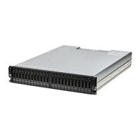
2U1219
-
2U2419
-
580W Pcm25
-
Installation35
-
HD Mini-SAS44
-
Operation54
-
Software/Ses55
-
Overview57
-
Leds57
-
IOM Leds60
-
PCM Faults61
-
Basic Steps63
-
Host I/O65
-
Overview77
-
Stopping I/O88
-
USB CLI Port101
-
Problem103
-
Workaround103
-
Index106

Advertisement