Sign In
Upload
Manuals
Brands
Seagate Manuals
Network Hardware
Exos AP 4U100
Seagate Exos AP 4U100 Manuals
Manuals and User Guides for Seagate Exos AP 4U100. We have
1
Seagate Exos AP 4U100 manual available for free PDF download: Installation And Maintenance Manual
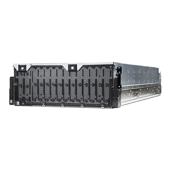
Seagate Exos AP 4U100 Installation And Maintenance Manual (134 pages)
Brand:
Seagate
| Category:
Network Hardware
| Size: 18.95 MB
Table of Contents
Table of Contents
3
Acronyms
11
About this Guide
14
Introduction
14
Intended Audience
14
Prerequisites
14
Document Conventions and Symbols
14
Document Conventions
14
Safety Guidelines
16
Safe Handling
16
Operation
16
Restricted Access
17
Electrical Safety
17
Rack System Safety Precautions
18
Leveling an Enclosure Rack
18
System Overview
19
Enclosure Configuration
19
4U100 Enclosure System - Dimetric Front Orientation
19
4U100 Enclosure System - Dimetric Rear Orientation
19
Enclosure Variants
20
4U100 Enclosure Description
20
Enclosure Main Components
21
Enclosure Front Panel
22
4U100 Enclosure System - Front Panel View
22
Enclosure Rear Panel
23
4U100 Enclosure System - Rear Panel Components
23
4U100 Enclosure - Rear Panel Module Slot Index Diagram (Viewed from Back)
24
Controller Module (Viewed from Back, Rotated by 90º)
24
Power Supply Unit (PSU) Module Detail
25
System Fan Module Detail (Viewed from Back)
26
SAS Expansion Ports at the Rear of 4U100 Enclosure
26
Enclosure Top
27
4U100 Enclosure - Top View with Lids
27
4U100 Enclosure - Top View Without Lids
29
4U100 Enclosure - Slot Index Diagram (Top View)
30
Enclosure Chassis
31
Overview of Front Panel Leds
32
System Power On/Standby LED (Green)
32
ID LED (Blue)
32
Port State LED (Green)
32
Fault LED-Top Lid a (Amber)
32
Application Fault Led/Logic Fault LED (Amber)
33
Fault LED-Rear Panel (Amber)
33
Fault LED-Top Lid Left (Top Lid B) (Amber)
33
Overview of Rear Panel Leds
33
Power Supply Unit
33
System Fan Module
34
System Airflow
35
Controller Module
36
Leds: Controller Module - Rear Panel
37
Overview of Top Leds
38
Drive Carrier Module
38
Controller Channel Fan Module
42
Leds: Controller Channel Fan Module - to be Inserted from Top
42
Storage Personality Module
43
Storage Personality Module LED Location
43
HS Expander Module
44
Enclosure Management
44
GEM Command-Line Interface (CLI)
44
Installation
45
Installation Checklist
45
Planning for Installation
45
Preparing for Installation
46
Preparing the Site
46
Storage System Configuration
46
Unpacking the Enclosure
47
Installing the Rack Mount Rail Kit
52
Measurement of Rack Post-To-Post Inside-Depth Distance
56
Measurement of Rail from Rear to Front Mount Bracket
57
Attaching Inner Rails to the Storage Enclosure
61
Installing the 4U100 Enclosure
63
Mounting the Storage Enclosure into the Rack Cabinet
63
Attachment of the CMA a Bracket
63
Installing the CMA and Crossbar
66
Attachment of the CMA C Bracket Assembly to the CMA a Bracket on the Chassis
67
Installing Drives
69
Routing Cables Using CMA
69
Cable Routing Sequence Using Standard Capacity CMA
70
Routing 10Gbe SFP+ Cables of the Left Controller
71
Routing 10Gbe SFP+ Cables of the Right Controller
72
Cable Routing Sequence Using High Capacity CMA
73
Routing Right Controller SAS Cables
75
Routing Right Controller Ethernet Cables
75
Cable Requirements for Expansion Enclosures
76
SAS Topology
76
Connecting 4U100 Enclosure to 4U106 Enclosures Using Daisy Chain Configuration
77
Connecting 4U100 Enclosure to 4U106 Enclosures Using Star Configuration
78
Power Cord Connection
79
Testing Enclosure Connections
79
Grounding Checks
79
Operation
80
Before You Begin
80
Powering On/Powering off
80
Troubleshooting and Problem Solving
81
Overview
81
Initial Start-Up Problems
81
Faulty Power Cords
81
Leds
81
PSU Leds
81
PSU LED States
81
Front Panel Leds
82
Drive Module Leds
82
Temperature Sensors
83
Troubleshooting
83
Expansion Port LED Status
83
PSU and System Fan Faults
84
Thermal Monitoring and Control
84
Thermal Alarm
85
Fault Isolation Methodology
85
Basic Steps
85
If the Enclosure Does Not Initialize
86
Host I/O
86
Dealing with Hardware Faults
86
Continuous Operation During Replacement
87
Firmware Updates
87
Customer-Replaceable Units (Crus)
87
Crus Addressing 4U100 Chassis
87
Module Removal and Replacement
89
Overview
89
ESD Precautions
89
Preventing Electrostatic Discharge
89
Grounding Methods to Prevent Electrostatic Discharge
90
Replacing a PSU Module
90
Removing a PSU Module
91
Installing a PSU Module
92
Replacing a System Fan Module
93
Removing a System Fan Module
93
Installing a System Fan Module
94
Removing a System Fan (1 of 2)
94
Removing a System Fan (2 of 2)
94
Replacing a Controller Channel Fan Module
95
Removing a Controller Channel Fan Module
95
Removing a Controller Fan (1 of 2)
95
Installing a Controller Channel Fan Module
96
Removing a Controller Fan (2 of 2)
96
Replacing a Storage Personality Module
97
Removing the SPM Air Retention Cover
97
Removing a Storage Personality Module
99
Installing Storage Personality Module
100
Removing a Storage Personality Module (1 of 2)
100
Removing a Storage Personality Module (2 of 2)
100
Replacing a HS Expander Module
102
Removing a HS Expander Module
102
Removing a HS Expander (1 of 2)
102
Installing an HS Expander Module
103
Replacing a Drive Module
103
Removing a HS Expander (2 of 2)
103
Removing a LFF Drive Carrier Module
104
Removing a LFF Drive Module (1 of 2)
104
Removing a LFF Drive Module (2 of 2)
104
Installing a LFF Drive Carrier Module
105
Replacing a Controller Module
106
Before You Begin
106
Verifying Component Failure
106
Controller Module Blank Inserted after Removing a Controller Module
106
Stopping I/O
107
Removing a Controller Module
107
Removing a Controller Module (1 of 2)
108
Removing a Controller Module (2 of 2)
108
Installing an Controller Module
111
Verifying Component Operation
111
A Technical Specifications
112
Enclosure Dimensions
112
Enclosure Weights
112
4U100 Enclosure Dimensions
112
Environmental Requirements
113
Power Supply Unit Specifications
114
B Standards and Regulations
115
International Standards
115
Potential for Radio Frequency Interference
115
European Regulations
115
Safety Compliance
115
Safety Compliance Specifications
115
EMC Compliance
116
AC Power Cords/Universal Jumper Cords
116
Environmental Standards
116
Recycling of Waste Electrical and Electronic Equipment (WEEE)
117
C Enclosure Packaging
118
4U100 Enclosure Packed in 3-Piece Box with Pallet
118
4U100 Enclosure Packed in RSC Box with Pallet
118
Unpacking the Enclosure: 3-Piece Box with Packing
120
Unpacking the Enclosure: RSC Box with Packing
121
DBIOS POST Codes
122
Introduction
122
List of POST Codes
122
SEC Phase
122
PEI Phase
123
DXE Phase
124
BDS Phase
125
Post BDS Phase
126
SMM Phase
126
ASL Functionality
127
Intel Reference Code POST Code
127
Memory RC POST Code
127
ASL Functionality POST Codes
127
Memory RC POST Codes
127
KIT RC POST Code
128
IIO RC POST Code
128
System BOOT POST Code Flow Sample
129
Cold Boot Flow
129
Warm Boot Flow
131
Index
134
Advertisement
Advertisement
Related Products
Seagate Serial ATA Native Command Queuing
Seagate SKYHAWK SURVEILLANCE AI 5 E Series
Seagate SKYHAWK SURVEILLANCE AI 512E
Seagate Exos E 4U106
Seagate EXOS 7E8 4kN
Seagate Exos Enterprise ST8000NM000A
Seagate Exos Enterprise ST8000NM008A
Seagate Exos Enterprise ST8000NM012A
Seagate Exos Enterprise ST4000NM012A
Seagate Exos Enterprise ST4000NM010A
Seagate Categories
Storage
Computer Hardware
Network Storage Server
Network Hardware
DC Drives
More Seagate Manuals
Login
Sign In
OR
Sign in with Facebook
Sign in with Google
Upload manual
Upload from disk
Upload from URL