Sign In
Upload
Manuals
Brands
Rheem Manuals
Heat Pump
RP1724AJVCA
Rheem RP1724AJVCA Manuals
Manuals and User Guides for Rheem RP1724AJVCA. We have
1
Rheem RP1724AJVCA manual available for free PDF download: Installation Instructions Manual
Rheem RP1724AJVCA Installation Instructions Manual (76 pages)
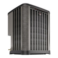
THREE STAGE R-410A HEAT PUMP OUTDOOR UNITS
Brand:
Rheem
| Category:
Heat Pump
| Size: 17.61 MB
Table of Contents
Table of Contents
2
Important Safety Information
3
General Information
4
Introduction
4
Agency Performance Audit Testing Notice
4
Importance of a Quality Installation
4
System Sizing and Selection
4
Importance of Proper Indoor/Outdoor Match-Ups
5
Checking Product Received
5
Compressor Break-In Notice
5
Unit Specifications
5
Model Number Nomenclature and Available Models
5
Electrical and Physical Data
6
Installation
7
Tools & Refrigerant
7
Tools Required for Installing & Servicing R-410A Models
7
Specifications of R-410A
7
Quick Reference Guide for R-410A
7
Choosing a Location
8
Allowable Clearances
8
Operational Issues Related to Unit Location
8
Corrosive Environments
9
Customer Satisfaction Issues
9
Mounting Unit
9
Unit-Mounting Methods
9
High Wind and Seismic Tie-Down Methods
9
Elevating Unit
10
Ground Snow Depth Table
10
Refrigerant Line Set Selection
11
Replacing Existing Systems
11
Line Set Application Considerations
11
Oil Return to Compressor
11
Refrigerant Migration During off Cycle
11
Maximum Liquid Pressure Drop
11
Liquid Line Refrigerant Flashing
11
Compressor Oil Level Adjustment
12
Capacity Losses
12
Line Set Length and Fitting Losses
12
Liquid Line Selection
13
Vapor Line Selection
13
Line Set Installation
16
Important Tubing Installation Practices
16
Relative Location of Indoor and Outdoor Units
17
Indoor and Outdoor Unit Near same Level
17
Outdoor Unit below Indoor Unit
18
Outdoor Unit above Indoor Unit
19
Tubing Connections
20
Initial Leak Testing
21
Evacuation
21
Final Leak Testing
22
Control Wiring
22
Econet TM Communications
22
TM Control Center Installation
22
TM Communication Wiring Connections
22
Conventional 24VAC Thermostat Control Wiring Connections
23
Power Wiring
24
Grounding
25
System Start-Up and Refrigerant Charging
25
System Start-Up Overview
25
Initial Power up and Econet
25
TM Communication Verification
25
Econet TM Control Center Set-Up
25
Initial System Set-Up
25
TM Control Center Service Menu
26
Setting up Charging Mode Using Variable Speed Outdoor Control Menu
26
Indoor Air-Flow Verification
27
Refrigerant Charging
27
Measurement Device Set-Up
28
Preliminary Charging by Weight
28
Preliminary Charging by Pressures
28
Final Charging by Liquid Subcooling
29
R-410A Temperature Pressure Chart
29
Completing Installation
29
Normal Sequence of Operation
30
Cooling Mode
30
On-Demand Cooling Dehumidification
30
Low Ambient Cooling Operation
30
Heating Mode
30
Supplemental Electric Heat During Heating Mode
31
Dual Fuel Applications - Heating Mode
31
Demand Defrost
31
Sequence of Operation for Conventional 24VAC Thermostat Controls
32
Components and Controls
33
Accumulator
33
Choke/Inductor
33
Coil Temperature Thermistor
33
Compressor
33
Compressor Sump Thermistor
33
Discharge Line Thermistor
33
Econet TM Variable Speed Outdoor Control (VSODC)
34
Board Features and Connections
34
TEST & SW2 Buttons
35
Memory Card
35
Factory Superheat Setting
35
Superheat Offset DIP Switch Settings
35
Defrost Termination Temperature DIP Switched
35
Menu Structure
36
Replacement of the VSODC
36
Electronic Expansion Valve
37
Filter & Ferrite Rings
37
High Pressure Control
38
Outdoor Ambient Temperature Thermistor
38
Outdoor Fan Motor
38
Outdoor Fan Blade
38
Power Inverter Compressor Control
38
Suction Pressure Transducer
39
Suction Temperature Thermistor
39
Active System Protection Features
40
Minimum Run Timer
40
Oil Return Cycle
40
Oil Dilution
40
Off-Cycle Refrigerant Migration - Stator Heat
40
High Discharge Temperature
40
High Discharge Pressure
40
Low Suction Pressure/Loss of Charge
41
Compressor Shut-Down Sequence for High or Low Refrigerant Pressure Fault
41
Overcurrent and Current Imbalance
41
Compressor Operation Outside Envelope
41
Over and under Voltage
42
Inverter over Temperature
42
Controls and Communication Malfunction
42
Sensor Failure Default Operation
42
Exiting Active Protection Lock-Out Mode
42
Diagnostics and Troubleshooting
43
Fault Recall Procedure
43
Compressor/Fan Motor Test Mode
43
Defrost Test Mode
43
Status and Diagnostic Codes
44
Active Protection Fault Details
52
Electrical Checks Flowchart
59
Cooling Mechanical Checks Flowchart
60
Heating Mechanical Checks Flowchart
61
Defrost Mechanical Checks Flowchart
62
Checking Transducers and Temperature Sensors
63
General Troubleshooting Guide
65
Service Analyzer Charts
66
Troubleshooting Tips
72
Outdoor Unit Maintenance
73
Outdoor Coil Cleaning
73
Cabinet Cleaning and Care
73
Motor Lubrication
73
Replacement Parts
73
Wiring Diagram
74
Appendix
75
Agency Performance Audit Test Instructions
75
Advertisement
Advertisement
Related Products
Rheem RP1336AD1NA
Rheem RP1342AD1NA
Rheem RP1430AJ1NA
Rheem RP1442AJ1NA
Rheem RP1442AC1NA
Rheem RP1448AC1NA
Rheem RP1460AD1NA
Rheem RP15
Rheem RP1524BJ1NA
Rheem RP1436AD1NA
Rheem Categories
Water Heater
Air Conditioner
Furnace
Heat Pump
Boiler
More Rheem Manuals
Login
Sign In
OR
Sign in with Facebook
Sign in with Google
Upload manual
Upload from disk
Upload from URL