Sign In
Upload
Manuals
Brands
Omron Manuals
Controller
OMNUC G5 R88D-KN series
Omron OMNUC G5 R88D-KN series Manuals
Manuals and User Guides for Omron OMNUC G5 R88D-KN series. We have
1
Omron OMNUC G5 R88D-KN series manual available for free PDF download: User Manual
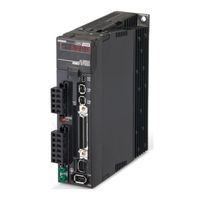
Omron OMNUC G5 R88D-KN series User Manual (458 pages)
AC SERVOMOTORS/SERVO DRIVES WITH BUILT-IN MECHATROLINK-II COMMUNICATIONS
Brand:
Omron
| Category:
Controller
| Size: 20.21 MB
Table of Contents
Safety Precautions Document
6
Items to Check after Unpacking
13
Manual Revision History
14
Structure of this Document
15
Table of Contents
16
Chapter 1 Features and System Configuration
24
Outline
24
Outline of the OMNUC G5 Series
24
Features of the OMNUC G5 Series
24
OMNUC G5-Series AC Servo Drives Users Manual (Built-In MECHATROLINK-II Communications
25
System Configuration
26
Names and Functions
27
Servo Drive Part Names
27
Servo Drive Functions
28
System Block Diagrams
29
Applicable Standards
30
EC Directives
30
UL and Cul Standards
30
Functional Safety
30
Chapter 2 Standard Models and External Dimensions
32
Servo System Configuration
32
How to Read Model
34
Servo Drive
34
Servomotor
35
Standard Model List
36
Servo Drive Model List
36
Servomotor Model List
37
Servo Drive and Servomotor Combination List
41
Cables and Peripheral Devices Model List
43
External and Mounting Dimensions
48
Servo Drive Dimensions
48
Servomotor Dimensions
59
External Regeneration Resistor Dimensions
78
EMC Filter Dimensions
79
MECHATROLINK-II Repeater Units
80
EMC Filter Dimensions
80
Chapter 3 Specifications
82
Servo Drive Specifications
82
General Specifications
82
Characteristics
83
Main Circuit and Motor Connections
89
Control I/O Connector Specifications (CN1)
94
Control Input Circuits
96
Control Input Details
97
Control Output Circuits
99
Control Output Details
100
Encoder Connector Specifications (CN2)
104
External Encoder Connector Specifications (CN4)
104
Monitor Connector Specifications (CN5)
108
USB Connector Specifications (CN7)
109
Safety Connector Specifications (CN8)
110
Overload Characteristics (Electronic Thermal Function)
112
Overload Characteristics Graphs
112
Servomotor Specifications
113
General Specifications
113
Characteristics
114
Encoder Specifications
137
Cable and Connector Specifications
138
Encoder Cable Specifications
138
Motor Power Cable Specifications
140
Connector Specifications
146
Analog Monitor Cable Specifications
149
MECHATROLINK-II Communications Cable Specifications
151
Control Cable Specifications
153
External Regeneration Resistor Specifications
158
External Regeneration Resistor Specifications
159
Reactor Filter Specifications
160
Specifications
160
MECHATROLINK-II Repeater Unit Specifications
161
Specifications
161
Repeater Unit Part Names
162
Connection Method
163
Chapter 4 System Design
166
Installation Conditions
166
Servo Drive Installation Conditions
166
Servomotor Installation Conditions
168
Decelerator Installation Conditions
171
Wiring
172
Peripheral Equipment Connection Examples
172
Main Circuit and Motor Connections
178
Wiring Conforming to EMC Directives
186
Wiring Method
186
Selecting Connection Component
191
Regenerative Energy Absorption
205
Calculating the Regenerative Energy
205
Servo Drive Regeneration Absorption Capacity
207
Regenerative Energy Absorption with an External Regeneration Resistor
208
Connecting an External Regeneration Resistor
209
Chapter 5 BASIC CONTROL Mode
212
Position Control
212
Parameters Requiring Settings
212
Related Functions
213
Parameter Block Diagram for POSITION CONTROL Mode
214
Speed Control
215
Parameters Requiring Settings
215
Related Functions
215
Parameter Block Diagram for SPEED CONTROL Mode
216
Torque Control
217
Parameters Requiring Settings
217
Related Functions
218
Parameter Block Diagram for TORQUE CONTROL Mode
219
Full Closing Control
220
Outline of Operation
220
Parameters Requiring Settings
221
Parameter Block Diagram for FULL CLOSING CONTROL Mode
227
Chapter 6 Applied Functions
230
Sequence I/O Signal
230
Input Signals
230
Output Signals
233
Forward and Reverse Drive Prohibition Functions
235
Parameters Requiring Settings
235
Overrun Protection
238
Operating Conditions
238
Parameters Requiring Settings
238
Operation Example
239
Backlash Compensation
240
Parameters Requiring Settings
240
Brake Interlock
242
Parameters Requiring Settings
242
Operating Example
243
Electronic Gear Function
247
Parameters Requiring Settings
247
Operation Example
249
Torque Limit Switching
250
Operating Conditions
250
Parameters Requiring Settings
250
Soft Start
252
Parameters Requiring Settings
252
Soft Start Acceleration or Deceleration Time
252
S-Curve Acceleration or Deceleration Time
253
Gain Switching Function
254
Parameters Requiring Settings
255
Gain Switching Setting for each CONTROL Mode
256
Timing by Gain Switching Setting
261
Gain Switching 3 Function
265
Operating Conditions
265
Parameters Requiring Settings
265
Operation Example
266
Chapter7 Safety Function
267
Safe Torque off (STO) Function
268
Functional Safety
268
I/O Signal Specifications
269
Operation Example
271
Connection Examples
273
Chapter 8 Parameters Details
276
Basic Parameters
276
Gain Parameters
283
Vibration Suppression Parameters
295
Analog Control Parameters
300
Interface Monitor Setting Parameters
306
Extended Parameters
317
Special Parameters
327
Chapter9 Operation
343
Operational Procedure
344
Preparing for Operation
345
Items to Check before Turning on the Power Supply
345
Turning on the Power Supply
347
Checking the Displays
348
Absolute Encoder Setup
349
Trial Operation
350
Preparation for Trial Operation
350
Trial Operation by Using the CX-Drive
350
Chapter10 Adjustment Functions
351
Analog Monitor
352
Parameters Requiring Settings
352
Gain Adjustment
355
Purpose of the Gain Adjustment
355
Gain Adjustment Methods
355
Gain Adjustment Procedure
356
Realtime Autotuning
357
Parameters Requiring Settings
358
Setting Realtime Autotuning
358
Setting Machine Rigidity
359
Manual Tuning
364
Basic Settings
364
Damping Control
372
Outline of Operation
372
Parameters Requiring Settings
373
Adaptive Filter
376
Parameters Requiring Settings
377
Operating Procedure
378
Notch Filter
379
Parameters Requiring Settings
380
Disturbance Observer Function
382
Operating Conditions
382
Parameters Requiring Settings
383
Operating Procedure
383
Friction Torque Compensation Function
384
Operating Conditions
384
Parameters Requiring Settings
384
Operation Example
385
Hybrid Vibration Suppression Function
386
Operating Conditions
386
Parameters Requiring Settings
386
Operating Procedure
386
Feed-Forward Function
387
Parameters Requiring Settings
387
Operating Procedure
388
Instantaneous Speed Observer Function
390
Operating Conditions
390
Parameters Requiring Settings
390
Operating Procedure
391
Chapter11 Error And Maintenance
393
Error Processing
394
Preliminary Checks When a Problem Occurs
394
Precautions When a Problem Occurs
395
Replacing the Servomotor and Servo Drive
396
Warning
397
Warning List
397
Alarms
399
Emergency Stop Operation at Alarms
406
Troubleshooting
408
Error Diagnosis Using the Alarm Displays
408
Error Diagnosis Using the Operation Status
420
Periodic Maintenance
428
Servomotor Life Expectancy
428
Servo Drive Life Expectancy
429
Replacing the Absolute Encoder Battery
430
Advertisement
Advertisement
Related Products
Omron OMNUC G5 R88M-K series
Omron G3PW-A245EU-C
Omron G3PX-260EHN-CT10
Omron G3PX-220EC-CT03
Omron G3PX-240EC-CT03
Omron G3ZA-8A403-FLK-UTU
Omron G3PX-240EH-CT03G3PX-240EH-CT10
Omron G9SP-N20S
Omron G3PX EUN Series
Omron G9SP-N10D
Omron Categories
Blood Pressure Monitor
Controller
Accessories
Switch
Inverter
More Omron Manuals
Login
Sign In
OR
Sign in with Facebook
Sign in with Google
Upload manual
Upload from disk
Upload from URL