Sign In
Upload
Manuals
Brands
OMRON Manuals
Computer Hardware
CP1L CPU UNIT - 03-2009
OMRON CP1L CPU UNIT - 03-2009 Manuals
Manuals and User Guides for OMRON CP1L CPU UNIT - 03-2009. We have
1
OMRON CP1L CPU UNIT - 03-2009 manual available for free PDF download: Operation Manual
OMRON CP1L CPU UNIT - 03-2009 Operation Manual (810 pages)
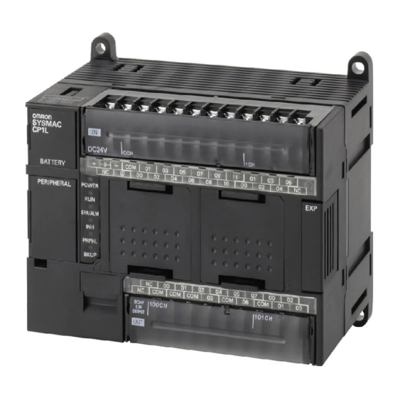
CP1L CPU Unit
Brand:
OMRON
| Category:
Computer Hardware
| Size: 16.89 MB
Table of Contents
Table of Contents
12
About this Manual
15
Related Manuals
17
Precautions
23
General Precautions
24
Intended Audience
24
Safety Precautions
24
Operating Environment Precautions
26
Application Precautions
27
Conformance to EC Directives
30
Applicable Directives
30
Relay Output Noise Reduction Methods
30
Conformance to EC Directives
32
Conditions for Meeting EMC Directives When Using CP/CPM1A Relay Expansion I/O Units
32
Section 1 Features and System Configuration
35
Features and System Configuration
35
Features and Main Functions
36
CP1L Overview
36
Features and Main Functions
38
Features
41
System Configuration
49
Basic System
49
Optional Products
50
Serial Communications
50
System Expansion
52
Restrictions on System Configuration
55
Connecting the CX-Programmer
57
Connecting with a Commercially Available USB Cable
58
Connecting to a Serial Port
65
Function Charts
67
Function Blocks
68
Overview of Function Blocks
68
Advantages of Function Blocks
68
Section 2 Nomenclature and Specifications
71
Nomenclature and Specifications
71
Part Names and Functions
72
CP1L CPU Units
72
CP1W-CIF01 RS-232C Option Boards
75
CP1W-CIF11/CIF12 RS-422A/485 Option Boards
76
Specifications
77
CP1L CPU Units
77
Current Consumption
80
I/O Memory Details
84
I/O Specifications
85
Input Specifications
98
Output Specifications
100
CP/CPM1A-Series Expansion I/O Unit I/O Specifications
103
CP1L CPU Unit Operation
107
Overview of CPU Unit Configuration
107
Flash Memory Data Transfers
111
Memory Cassette Data Transfers
113
CPU Unit Operation
115
General Flow
115
I/O Refresh Methods
116
I/O Refreshing and Peripheral Servicing
116
Initialization at Startup
118
CPU Unit Operating Modes
119
Operating Modes
119
Status and Operations in each Operating Mode
119
Operating Mode Changes and I/O Memory
120
Startup Mode Setting
120
Power off Operation
121
Overview
121
Description of Operation
122
Instruction Execution for Power Interruptions
122
Computing the Cycle Time
123
CPU Unit Operation Flowchart
123
Cycle Time Overview
124
Functions Related to the Cycle Time
125
Minimum Cycle Time
125
Cycle Time Calculation Example
127
I/O Refresh Times for PLC Units
127
Online Editing Cycle Time Extension
128
I/O Response Time
129
Interrupt Response Times
130
Serial PLC Link Response Performance
131
2-7-10 Pulse Output Start Time
132
2-7-11 Pulse Output Change Response Time
132
Section 3 Installation and Wiring
133
Fail-Safe Circuits
134
Installation Precautions
135
Installation and Wiring Precautions
135
Mounting
137
Mounting in a Panel
137
Connecting Expansion Units and Expansion I/O Units
140
Mounting Height
140
DIN Track Installation
142
Wiring CP1L CPU Units
144
Wiring Power Supply and Ground Lines
145
Wiring Built-In I/O
147
Wiring Safety and Noise Controls
150
Wiring CPU Unit I/O
152
I/O Wiring for CPU Units with 60 I/O Points
152
I/O Wiring for CPU Units with 40 I/O Points
153
I/O Wiring for CPU Units with 30 I/O Points
155
I/O Wiring for CPU Units with 20 I/O Points
156
I/O Wiring for CPU Units with 14 I/O Points
158
I/O Wiring for CPU Units with 10 I/O Points
159
Pulse Input Connection Examples
161
Pulse Output Connection Examples
161
CP/CPM1A-Series Expansion I/O Unit Wiring
164
Section 4 I\/O Memory Allocation
171
I/O Memory Allocation
171
Overview of I/O Memory Area
172
I/O Memory Area
172
Overview of the Data Areas
173
Clearing and Holding I/O Memory
177
Hot Start/Hot Stop Functions
177
I/O Area and I/O Allocations
179
I/O Bits Allocated to CPU Units
180
I/O Bits Allocated to Expansion I/O Units
182
I/O Allocation Examples with Expansion I/O Units
184
I/O Word Allocations to Expansion Units
185
1:1 Link Area
186
Serial PLC Link Area
187
Internal Work Area
187
Holding Area (H)
188
Auxiliary Area (A)
189
TR (Temporary Relay) Area
189
Timers and Counters
190
Timer Area (T)
190
Counter Area (C)
191
Changing the BCD or Binary Mode for Counters and Timers
193
Data Memory Area (D)
194
4-11 Index Registers
195
4-11-1 Using Index Registers
199
4-11-2 Precautions for Using Index Registers
201
4-12 Data Registers
203
4-13 Task Flags
205
4-14 Condition Flags
205
4-15 Clock Pulses
207
Section 5 Pulse and Counter Functions
209
Pulse and Counter Functions
209
High-Speed Counters
210
Overview
210
High-Speed Counter Specifications
211
Procedure
216
PLC Setup
217
High-Speed Counter Terminal Allocation
218
Ladder Program Example
224
Pulse Input Connection Examples
224
Additional Capabilities and Restrictions
227
Pulse Outputs
231
Overview
231
Pulse Output Specifications
234
Pulse Output Terminal Allocations
235
Pulse Output Patterns
242
Origin Search and Origin Return Functions
254
Related Auxiliary Area Flags
267
Origin Return
271
Pulse Output Procedures
273
Instructions Used for Pulse Outputs
275
5-2-10 Example Pulse Output Applications
284
Variable Duty Factor Pulse Outputs (PWM(891) Outputs)
284
Cutting Long Material Using Fixed Feeding
291
Inverter Positioning
314
Features
314
System Configuration
317
Functional Overview
318
Specifications
320
Application Procedure for Inverter Positioning
322
Instruction Specifications
323
Determining the Internal Pulse Output Frequency
329
Basic Settings
331
PLC Setup
331
Automatic Calculation of Inverter Frequency Command Value
336
5-3-10 Memory Allocations
339
Auxiliary Area
340
5-3-11 Application Example with Serial Communications
351
Connection Example
353
5-3-12 Application Example with an Analog Output
361
5-3-13 Supplemental Information
370
Advanced Functions
371
Interrupt Functions
372
Overview of Cp1L Interrupt Functions
372
Input Interrupts (Direct Mode)
376
Input Interrupts (Counter Mode)
381
Scheduled Interrupts
384
High-Speed Counter Interrupts
387
Quick-Response Inputs
396
Serial Communications
400
No-Protocol Communications
402
Modbus-Rtu Easy Master Function
405
Communications: Smart Active Parts and Function Blocks
408
Serial Plc Links
410
N Nt Links
420
Host Link Communications
422
Analog Adjuster and External Analog Setting Input
427
Battery-Free Operation
428
Using Battery-Free Operation
429
Memory Cassette Functions
430
Mounting and Removing a Memory Cassette
431
Operation Using the CX-Programmer
433
Memory Cassette Data Transfer Function
434
Copying the System
437
Program Protection
438
Operating from a Memory Cassette
438
Read Protection
438
Write Protection
444
Protecting Program Execution Using the Lot Number
446
Failure Diagnosis Functions
447
Simulating System Errors
449
Output off Bit
450
Clock
451
Using Expansion Units and Expansion I/O Units
453
Connecting Expansion Units and Expansion I/O Units
454
Analog Input Units
455
Analog Input Signal Ranges
457
Analog Output Units
464
Analog Output Signal Ranges
466
Analog I/O Units
472
Cpm1A-Mad01 Analog I/O Units
472
Cp1W-Mad11/Cpm1A-Mad11 Analog I/O Units
482
Temperature Sensor Units
495
Main Specifications
496
Compobus/S I/O Link Units
510
Operating Procedure
513
Devicenet I/O Link Units
516
LCD Option Board
523
Features
524
Specifications
525
Part Names
526
Installation and Removing
527
Basic Operation
528
Screen Transitions
529
Operation Examples
531
LCD Option Board Function
533
Function Overview
533
Plc Mode
536
I/O Memory Setting
537
Memory Cassette
548
Message Screen
561
Data Backup
572
Language Selection
575
Plc Cycle Time
576
Plc Clock Setting
577
Plc System Information
578
Lcd Backlight Setting
579
Lcd Contrast Setting
580
Lcd Factory Setting
581
Trouble Shooting
582
Communication Error Message During Operation
582
Symptom at Power on or During Operation
582
Deleting Eeprom Error
583
Ethernet Option Board
585
Ethernet Option Board Function Guide
586
Overall System Configuration Example
586
Connecting the CX-Programmer to Plcs Online Via Ethernet
587
Receiving Data from Omron Plcs Using Ethernet
588
Differential Monitoring
589
Devices Required for Constructing a Network
590
System Configuration
590
Specifications
591
FINS Communications
592
Fins Communications Service Specifications
592
Overview of Fins Communication Service
593
Part Names
594
Comparison with Previous Models
595
Installation and Initial Setup
596
Overview of Startup Procedure
596
Network Installation
598
Web Browser Setting Function
601
Cio Area Allocation
603
Memory Allocations
603
Error Status
604
DM Area Allocation
605
Mode Setting
606
Subnet Mask
606
Web Browser Setup and Display
609
Multi-Language Function
609
Overview of Web Browser Function
609
Unit Information
616
Unit Status
617
Fins Status
618
Error Log
619
Trouble Shooting
620
Trouble-Shooting with Indicators and Error Code Display
623
Sample Application
625
Program Transfer, Trial Operation, and Debugging
631
Program Transfer
632
Trial Operation and Debugging
632
Forced Set/Reset
632
Tracing Data
636
Troubleshooting
639
Error Classification and Confirmation
640
Troubleshooting
642
Error Processing Flowchart
642
No Operation When Power Is Supplied
642
Fatal Errors
643
Reference Information
646
Cpu Errors
647
Other Errors
650
Error Log
651
Troubleshooting Unit Errors
652
Inspection and Maintenance
655
Inspections
656
Unit Replacement Precautions
657
Replacing User-Serviceable Parts
658
A Standard Models
663
Programming Devices
664
Expansion Units
666
B Dimensions Diagrams
669
Cpu Unit Settings
677
Initial Settings
677
Data Tracing
685
Comment Memory
686
E Memory Map
747
Memory Map
748
Connection Methods
749
Connection Examples
767
Input Constant Settings
778
Pulse Output 0 Settings
790
Pulse Output 1 Settings
793
Index
801
Revision History
807
Advertisement
Advertisement
Related Products
Omron SYSMAC CP1L-M60DR-A
Omron SYSMAC CP1L-M60DT-D
Omron SYSMAC CP1L-M60DT1-D
Omron SYSMAC CP1L-M40DR-D
Omron SYSMAC CP1L-M30DT-D
Omron SYSMAC CP1L-M30DT1-D
Omron SYSMAC CP1L-L20DT-A
Omron SYSMAC CP1L-J20DT1-D
Omron SYSMAC CP1L-L14DR-A
Omron SYSMAC CP1L-L14DR-D
OMRON Categories
Blood Pressure Monitor
Controller
Accessories
Switch
Inverter
More OMRON Manuals
Login
Sign In
OR
Sign in with Facebook
Sign in with Google
Upload manual
Upload from disk
Upload from URL