Sign In
Upload
Manuals
Brands
motorola Manuals
Control Unit
MVME712M
motorola MVME712M Manuals
Manuals and User Guides for motorola MVME712M. We have
3
motorola MVME712M manuals available for free PDF download: Installation And Use Manual, User Manual
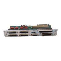
Motorola MVME712M Installation And Use Manual (80 pages)
Transition Module
Brand:
Motorola
| Category:
Computer Hardware
| Size: 3.52 MB
Table of Contents
Table of Contents
7
Introduction
11
Description
11
MVME712M Transition Module
12
P2 Adapter Board
12
Specifications
13
Table 1-1. MVME712M Specifications
13
Cooling Requirements
14
FCC Compliance
15
Related Documentation
16
MCG Customer Services
17
Introduction
18
Unpacking the Hardware
18
Preparing the MVME712M Module
19
DTE/DCE Configuration Select Headers
19
Table 2-1. Serial Port Jumpers/Headers
19
Figure 2-1. MVME712M Header Locations
20
Serial Port 1 DCE Configuration -- J1 and J11
21
Serial Port 1 DTE Configuration -- J1 and J11
21
Figure 2-2. Serial Port 1 Configured as DCE
21
Figure 2-3. Serial Port 1 Configured as DTE
22
Serial Port 2 DCE Configuration -- J16 and J17
23
Serial Port 2 DTE Configuration -- J16 and J17
23
Figure 2-4. Serial Port 2 Configured as DCE
23
Figure 2-5. Serial Port 2 Configured as DTE
24
Serial Port 3 DCE Configuration -- J13 and J14
25
Figure 2-6. Serial Port 3 Configured as DCE
25
Serial Port 3 DTE Configuration - J13 and J14
26
Figure 2-7. Serial Port 3 Configured as DTE
26
Serial Port 4 DCE Configuration -- J18 and J19
27
Figure 2-8. Serial Port 4 Configured as DCE
27
Serial Port 4 DTE Configuration - J18 and J19
28
Figure 2-9. Serial Port 4 Configured as DTE
28
Figure 2-10. J15 Clock Line Configuration
29
Table 2-2. Vmemodule Headers/Switches
29
SCSI Termination
30
Preparing the P2 Adapter Board
31
Figure 2-11. P2 Adapter Connector Locations
31
Cables and Connectors
32
Table 2-3. Cables and Connectors
32
Installing the MVME712M Module and P2 Adapter Board
34
Procedure
34
Table 2-4. Cabling Configurations
35
Configuration a - Internal SCSI Devices Only
36
Figure 2-12. Configuration a -- Internal-Only SCSI Connections
37
Configuration B - Internal SCSI Devices Only
38
Figure 2-13. Configuration B -- Internal-Only SCSI Connections
39
Configuration B1 - Internal SCSI Devices Only
40
Figure 2-14. Configuration B1 -- Internal-Only SCSI Connections
41
Configuration C - Internal and External SCSI Devices
42
Figure 2-15. Configuration C -- Internal and External SCSI Connections
44
Configuration C1 - Internal and External SCSI Devices
45
Figure 2-16. Configuration C1 -- Internal and External SCSI Connections
46
Configuration D - Internal and External SCSI Devices
47
Figure 2-17. Configuration D -- Internal and External SCSI Connections
49
Configuration E - External SCSI Devices Only
50
Figure 2-18. Configuration E -- External-Only SCSI Connections
51
Configuration F - External SCSI Devices Only
52
Figure 2-19. Configuration F -- External-Only SCSI Connections
54
Introduction
55
Table 3-1. P2 Adapter Board and MVME712M Connectors
55
P2 Adapter Board
56
P2 Connector
56
J2 Connector
56
Table 3-2. Connector J2 Interconnect Signals
56
J3 Connector
61
Table 3-3. Connector J3 Interconnect Signals
61
MVME712M Transition Module
63
J2 Connector
63
Table 3-4. Connector J2 Interconnect Signals
63
J3 and J4 Connectors
68
Table 3-5. Connectors J3 and J4 Interconnect Signals
68
SCSI Interface Connector
70
Table 3-6. Connector SCSI Interface Interconnect Signals
70
J5 Connector
72
Table 3-7. Connector J5 Interconnect Signals
72
J6 Connector
73
Table 3-8. Connector J6 Interconnect Signals
73
J7 - J10 Connectors
74
Table 3-9. Connectors J7 - J10 Interconnect Signals
74
J20 Connector
75
Table 3-10. Connector J20 Interconnect Signals
75
J21 Connector
76
Table 3-11. Connector J21 Interconnect Signals
76
Advertisement
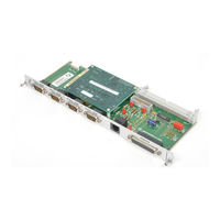
motorola MVME712M Installation And Use Manual (78 pages)
Transition Module
Brand:
motorola
| Category:
Control Unit
| Size: 0.29 MB
Table of Contents
Table of Contents
7
Chapter 1 General Information
11
Introduction
11
Description
11
MVME712M Transition Module
12
P2 Adapter Board
12
Specifications
13
Table 1-1. MVME712M Specifications
13
Cooling Requirements
14
FCC Compliance
15
Chapter 2 Preparing and Installing the Hardware
17
Introduction
17
Unpacking the Hardware
17
Preparing the MVME712M Module
17
DTE/DCE Configuration Select Headers
18
Figure 2-1. MVME712M Header Locations
19
Figure 2-2. Serial Port 1 Configured as DCE
20
Serial Port 1 DCE Configuration -- J1 and J11
20
Figure 2-3. Serial Port 1 Configured as DTE
21
Serial Port 1 DTE Configuration -- J1 and J11
21
Figure 2-4. Serial Port 2 Configured as DCE
22
Serial Port 2 DCE Configuration -- J16 and J17
22
Figure 2-5. Serial Port 2 Configured as DTE
23
Serial Port 2 DTE Configuration -- J16 and J17
23
Figure 2-6. Serial Port 3 Configured as DCE
24
Serial Port 3 DCE Configuration -- J13 and J14
24
Figure 2-7. Serial Port 3 Configured as DTE
25
Serial Port 3 DTE Configuration - J13 and J14
25
Figure 2-8. Serial Port 4 Configured as DCE
26
Serial Port 4 DCE Configuration -- J18 and J19
26
Figure 2-9. Serial Port 4 Configured as DTE
27
Serial Port 4 DTE Configuration - J18 and J19
27
Figure 2-10. J15 Clock Line Configuration
28
SCSI Termination
28
Serial Port 4 Clock Configuration Select Header -- J15
28
Table 2-1. MPU Jumpers/Switches for Clock Signals
28
Preparing the P2 Adapter Board
29
Cables and Connectors
29
Figure 2-11. P2 Adapter Connector Locations
29
Table 2-2. Cables and Connectors
30
Installing the MVME712M Module and P2 Adapter Board
33
Table 2-3. MVME712M Configurations
33
Configuration a - Internal SCSI Devices Only
34
Figure 2-12. Configuration a -- Internal-Only SCSI Connections
35
Configuration B - Internal SCSI Devices Only
36
Figure 2-13. Configuration B -- Internal-Only SCSI Connections
37
Configuration B1 - Internal SCSI Devices Only
38
Figure 2-14. Configuration B1 -- Internal-Only SCSI Connections
39
Configuration C - Internal and External SCSI Devices
40
Figure 2-15. Configuration C -- Internal and External SCSI Connections
41
Configuration C1 - Internal and External SCSI Devices
42
Figure 2-16. Configuration C1 -- Internal and External SCSI
43
Configuration D - Internal and External SCSI Devices
44
Figure 2-17. Configuration D -- Internal and External SCSI Connections
45
Configuration E - External SCSI Devices Only
46
Figure 2-18. Configuration E -- External-Only SCSI Connections
47
Configuration F - External SCSI Devices Only
48
Figure 2-19. Configuration F -- External-Only SCSI Connections
49
Chapter 3 Interconnect Signals
51
Introduction
51
Table 3-1. P2 Adapter Board and MVME712M Connectors
51
P2 Adapter Board
52
P2 Connector
52
J2 Connector
52
Table 3-2. Connector J2 Interconnect Signals
52
J3 Connector
57
Table 3-3. Connector J3 Interconnect Signals
57
MVME712M Transition Module
60
J2 Connector
60
Table 3-4. Connector J2 Interconnect Signals
60
J3 and J4 Connectors
64
Table 3-5. Connectors J3 and J4 Interconnect Signals
64
SCSI INTERFACE Connector
67
Table 3-6. Connector SCSI INTERFACE Interconnect Signals
67
J5 Connector
68
Table 3-7. Connector J5 Interconnect Signals
69
J6 Connector
70
Table 3-8. Connector J6 Interconnect Signals
70
J7 - J10 Connectors
71
Table 3-9. Connectors J7 - J10 Interconnect Signals
71
J20 Connector
72
Table 3-10. Connector J20 Interconnect Signals
72
J21 Connector
73
Table 3-11. Connector J21 Interconnect Signals
73
Index
75
Motorola MVME712M User Manual (74 pages)
Transition Modules and LCP2 Adapter Board
Brand:
Motorola
| Category:
Computer Hardware
| Size: 0.5 MB
Table of Contents
Related Documentation
3
Table of Contents
9
Introduction
12
Features of the MVME712 Family Modules
12
Features of the LCP2 Adapter Board
13
Speciþcations
13
Cooling Requirements
14
FCC Compliance
14
General Description
15
Introduction
16
Unpacking Instructions
16
Mvme712X Module Preparation
16
MVME712-12 Header Locations
17
MVME712-13 Header Locations
18
MVME712A Header Locations
19
MVME712AM Header Locations
20
DSR Line Pull up Select Headers (J8, J9, J13, J14)
21
Serial Port 2/Modem Port 2 Select (J16, J17)
22
Serial Port Configuration
22
Modem Port Configuration
22
SCSI Termination
23
MVME712B Module Preparation
23
MVME712B Connector Locations
24
LCP2 Adapter Board Preparation
25
LCP2 Adapter Connector Locations
25
Installation Instructions
26
Installing for Use with Internal SCSI Devices
26
Installing the MVME712-13 and MVME712AM as a Modem
26
MVME712B Installation
26
Internal SCSI and Serial Port Connections
28
Internal SCSI and Modem Connections
30
MVME712B External SCSI Connections
32
Introduction
34
Interconnect Signals
34
Connector P2 Interconnect Signals (LCP2 Adapter)
35
Connectors J1, J3-J5 Interconnect Signals (Mvme712X)
35
Connector J2 Interconnect Signals (LCP2 Adapter)
37
Connector J2 Interconnect Signals (MVME712-13, MVME712AM)
42
Connector J3 Interconnect Signals (LCP2 Adapter) Connector
42
Connector SCSI INTERFACE Interconnect Signals (MVME712B)
44
Connector ETHERNET Interconnect Signals (MVME712B)
46
Connector J6 Interconnect Signals (MVME712-13, MVME712AM)
47
Connector J7 Interconnect Signals (MVME712-13, MVME712AM)
47
Connector J10 Interconnect Signals (Mvme712X)
48
Connector P2 and J11 Interconnect Signals (Mvme712X)
49
Connector J12 Interconnect Signals (MVME712-13, MVME712AM)
53
Connector J15 Interconnect Signals (Mvme712X)
54
Parts Lists and Locations
55
Support Information
59
Schematic Drawings
66
General Description
68
Modem Features
69
Advertisement
Advertisement
Related Products
Motorola MVME712-10
Motorola MVME712 Series
Motorola MVME712-06
Motorola MVME712-07
Motorola MVME712-09
Motorola MVME712-11
Motorola MVME712-102
Motorola MVME712-103
Motorola MVME712-104
Motorola MVME712-376
motorola Categories
Cell Phone
Two-Way Radio
Baby Monitor
Cordless Telephone
Radio
More motorola Manuals
Login
Sign In
OR
Sign in with Facebook
Sign in with Google
Upload manual
Upload from disk
Upload from URL