Table of Contents
Advertisement
Quick Links
Advertisement
Table of Contents

Related Manuals for Motorola MVME712M


Summary of Contents for Motorola MVME712M
- Page 1 MVME712M Transition Module and P2 Adapter Board Installation and Use VME712MA/IH1...
- Page 2 Motorola, Inc. assumes no liability resulting from any omissions in this document, or from the use of the information obtained therein. Motorola reserves the right to revise this document and to make changes from time to time in the content hereof without obligation of Motorola to notify any person of such revision or changes.
- Page 3 Use, part number VME712MA/IH1, provides general information, hardware preparation, installation instructions, and support information for the MVME712M Transition Module and the P2 Adapter Board. It replaces an earlier version of the manual, part number MVME712M/D2. The modules are used as the interface between the following families of Motorola...
- Page 4 Related Documentation The Motorola publications listed below are referenced in this document. They may be purchased, depending upon availability, by contacting your local Motorola sales office. Motorola Document Title Publication Number MVME147-0xx MPU VMEmodule Installation and Use VME147A/IH MVME162 Embedded Controller Installation Guide...
- Page 5 Motorola, Inc. assumes no liability for the customer's failure to comply with these requirements. The safety precautions listed below represent warnings of certain dangers of which Motorola is aware. You, as the user of the product, should follow these warnings and all other safety precautions necessary for the safe operation of the equipment in your operating environment.
- Page 6 All Motorola PWBs (printed wiring boards) are manufactured by UL-recognized manufacturers, with a flammability rating of 94V-0. This equipment generates, uses, and can radiate electro- magnetic energy. It may cause or be susceptible to electro- magnetic interference (EMI) if not installed and used in a WARNING cabinet with adequate EMI protection.
-
Page 7: Table Of Contents
SCSI Termination .................. 2-12 Preparing the P2 Adapter Board..............2-13 Cables and Connectors..................2-13 Installing the MVME712M Module and P2 Adapter Board ......2-16 Configuration A - Internal SCSI Devices Only........2-18 Configuration B - Internal SCSI Devices Only ........2-20 Configuration B1 - Internal SCSI Devices Only ........ - Page 8 P2 Adapter Board....................3-2 P2 Connector ....................3-2 J2 Connector ....................3-2 J3 Connector ....................3-7 MVME712M Transition Module ..............3-10 J2 Connector ....................3-10 J3 and J4 Connectors ................... 3-14 SCSI INTERFACE Connector ..............3-17 J5 Connector ....................3-18 J6 Connector ....................
- Page 9 Figures Figure 2-1. MVME712M Header Locations ............. 2-3 Figure 2-2. Serial Port 1 Configured as DCE ........... 2-4 Figure 2-3. Serial Port 1 Configured as DTE............ 2-5 Figure 2-4. Serial Port 2 Configured as DCE ........... 2-6 Figure 2-5. Serial Port 2 Configured as DTE............ 2-7 Figure 2-6.
- Page 10 Table 2-1. MPU Jumpers/Switches for Clock Signals........2-12 Table 2-2. Cables and Connectors ..............2-14 Table 2-3. MVME712M Configurations............2-17 Table 3-1. P2 Adapter Board and MVME712M Connectors......3-1 Table 3-2. Connector J2 Interconnect Signals ........... 3-2 Table 3-3. Connector J3 Interconnect Signals ........... 3-7 Table 3-4.
-
Page 11: Introduction
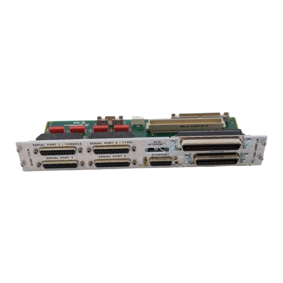
The serial ports may be configured for EIA-232-D DTE or DCE through jumper arrangements on the MVME712M. The MVME712M front panel also has an Ethernet port, a SCSI port, and a printer port. In addition, the MVME712M routes the EIA-232-... -
Page 12: Mvme712M Transition Module
Radio Frequency Interference (RFI) protection on front panel Electrostatic Discharge (ESD) protection on front panel P2 Adapter Board The MVME712M requires the use of the P2 Adapter Board. The features of the P2 Adapter Board include: A connector that permits SCSI cable connection to other SCSI... -
Page 13: Specifications
Specifications Specifications Table 1-1 lists the general specifications for the MVME712M Transition Module. The subsequent sections detail cooling requirements and FCC compliance. A complete functional description of the MVME712M appears in Chapter 2. Table 1-1. MVME712M Specifications Characteristics Specifications Power requirements... -
Page 14: Cooling Requirements
General Information Cooling Requirements Motorola VMEmodules are specified, designed, and tested to operate reliably with an incoming air temperature range from 0 degrees C to 55 degrees C (32 degrees F to 131 degrees F) with forced air cooling. Temperature qualification is performed in a standard Motorola VMEsystem 1000 chassis. -
Page 15: Fcc Compliance
Specifications FCC Compliance This VMEmodule (MVME712M) was tested in an FCC-compliant chassis, and meets the requirements for Class A equipment. FCC compliance was achieved under the following conditions: Shielded cables on all external I/O ports Cable shields connected to earth ground via metal shell connectors bonded to a conductive module front panel Conductive chassis rails connected to earth ground;... - Page 16 General Information...
-
Page 17: Introduction
Preparing the MVME712M Module The locations of the headers, LEDs, terminators, and connectors for the MVME712M are shown in Figure 2-1. The module has been factory tested and is shipped with factory-installed jumpers that configure the MVME712M to provide the system functions... -
Page 18: Dte/Dce Configuration Select Headers
Serial Ports 1 through 4 can be configured as a modem (DCE) for connection to terminal or configured as a terminal (DTE) for connection to modem. The MVME712M is shipped with the ports configured for DTE operation. Configuration of each port is accomplished by positioning jumpers on one of two headers for each port: Configure these... -
Page 19: Figure 2-1. Mvme712M Header Locations
Preparing the MVME712M Module MVME712M Figure 2-1. MVME712M Header Locations... -
Page 20: Serial Port 1 Dce Configuration -- J1 And J11
To configure Port 1 for DCE (modem to terminal) operation, install jumpers on headers J1 and J11 as shown below. The schematic representation of this configuration is shown in Figure 2-2. MVME xxxx Processor VMEmodule 64 PIN MVME712M ADAPTER CABLE TRANSITION BOARD... -
Page 21: Serial Port 1 Dte Configuration -- J1 And J11
Preparing the MVME712M Module Serial Port 1 DTE Configuration -- J1 and J11 To configure Port 1 for DTE (terminal to modem) operation, remove jumpers from header J1 and install jumpers on header J11 as shown below. This is the default configuration as shipped from the factory. -
Page 22: Serial Port 2 Dce Configuration -- J16 And J17
To configure Port 2 for DCE (modem to terminal) operation, install jumpers on header J16 and remove jumpers from header J17 as shown below. The schematic representation of this configuration is shown in Figure 2-4. MVME xxxx Processor VMEmodule 64 PIN MVME712M ADAPTER CABLE TRANSITION BOARD BOARD... -
Page 23: Serial Port 2 Dte Configuration -- J16 And J17
Preparing the MVME712M Module Serial Port 2 DTE Configuration -- J16 and J17 To configure Port 2 for DTE (terminal to modem) operation, remove jumpers from header J16 and install jumpers on header J17 as shown below. This is the default configuration as shipped from the factory. -
Page 24: Serial Port 3 Dce Configuration -- J13 And J14
To configure Port 3 for DCE (modem to terminal) operation, install jumpers on header J13 and remove jumpers from header J14 as shown below. The schematic representation of this configuration is shown in Figure 2-6. MVME xxxx Processor VMEmodule 64 PIN MVME712M ADAPTER CABLE TRANSITION BOARD BOARD... -
Page 25: Serial Port 3 Dte Configuration - J13 And J14
Preparing the MVME712M Module Serial Port 3 DTE Configuration - J13 and J14 To configure Port 3 for DTE (terminal to modem) operation, remove jumpers from header J13 and install jumpers on header J14 as shown below. This is the default configuration as shipped from the factory. -
Page 26: Serial Port 4 Dce Configuration -- J18 And J19
To configure Port 4 for DCE (modem to terminal) operation, install jumpers on header J18 and remove jumpers from header J19 as shown below. The schematic representation of this configuration is shown in Figure 2-8. MVME xxxx Processor VMEmodule 64 PIN MVME712M ADAPTER CABLE TRANSITION BOARD BOARD... -
Page 27: Serial Port 4 Dte Configuration - J18 And J19
Preparing the MVME712M Module Serial Port 4 DTE Configuration - J18 and J19 To configure Port 4 for DTE (terminal to modem) operation, remove jumpers from header J18 and install jumpers on header J19 as shown below. This is the default configuration as shipped from the factory. -
Page 28: Serial Port 4 Clock Configuration Select Header -- J15
You must ensure that the SCSI bus is terminated properly. The P2 adapter and the MVME712M module have sockets for terminating the SCSI lines. Both the P2 adapter and the MVME712M use three 8-pin Single In-line Package (SIP) resistors. Refer to the installation instructions in Installing the MVME712M, in this cahpter, for details on use of the terminators. -
Page 29: Preparing The P2 Adapter Board
Figure 2-11. P2 Adapter Connector Locations Cables and Connectors The MVME712M front panel has four serial ports, one printer port, one SCSI port, and one Ethernet port. The connectors for these ports, the P2 backplane connector, and two modem connectors are described in Table 2-2. -
Page 30: Table 2-2. Cables And Connectors
Preparing and Installing the Hardware Cables recommended for use with the connectors are also listed in the table. Note that not all peripheral cables needed are provided with the MVME712M; you may need to fabricate or purchase certain cables. Table 2-2. Cables and Connectors... - Page 31 64-pin male connector that 17.5-inch 64-conductor flat cables to J2 on the P2 ribbon cable, part number adapter board 30-W2514B02, furnished with the MVME712M (see Note below) P2 Adapter Board Interconnection Connector Description Cable 96-pin female DIN 41612...
- Page 32 If you wish to use your own cable for the P2 signals from J2 on the Note P2 adapter board to J2 on the MVME712M, note that the cable should be kept as short as possible. Any cable over 3 feet is likely to cause signal problems.
-
Page 33: Installing The Mvme712M Module And P2 Adapter Board
Installing the MVME712M Module and P2 Adapter Board Connecting modules while power is applied may result in damage to components on the module. Caution Dangerous voltages, capable of causing death, are present in this equipment. Use extreme caution when handling, testing, and adjusting. -
Page 34: Configuration A - Internal Scsi Devices Only
8. Connect the power cable to the power source and turn the unit on. 9. The yellow LED (DS1) on the MVME712M should be lit (the LED can be seen through the opening in the front panel). If not lit, then either a cabling problem exists, a fuse is blown, or both. -
Page 35: Figure 2-12. Configuration A -- Internal-Only Scsi Connections
Installing the MVME712M Module and P2 Adapter Board TERMINATORS SCSI INSTALLED DEVICE SCSI DEVICE MVME712M MVME xxxx Processor VMEmodule 50-CONDUCTOR CABLE 64-CONDUCTOR CABLE P2 ADAPTER TERMINATORS TERMINATORS REMOVED INSTALLED ENCLOSURE BOUNDARY cb2349301A Figure 2-12. Configuration A -- Internal-Only SCSI Connections... -
Page 36: Configuration B - Internal Scsi Devices Only
1. The MVMExxxx processor VMEmodule is at one end of the cable, so terminators must be installed on the P2 adapter module. 2. The MVME712M is at one end of the cable, so terminators must be installed on the MVME712M. -
Page 37: Figure 2-13. Configuration B -- Internal-Only Scsi Connections
Installing the MVME712M Module and P2 Adapter Board SCSI DEVICE SCSI DEVICE MVME xxxx Processor VMEmodule MVME712M P2 ADAPTER 64-CONDUCTOR CABLE TERMINATORS TERMINATORS INSTALLED INSTALLED 50-CONDUCTOR CABLE ENCLOSURE BOUNDARY cb2359301A Figure 2-13. Configuration B -- Internal-Only SCSI Connections 2-21... -
Page 38: Configuration B1 - Internal Scsi Devices Only
1. The MVMExxxx processor VMEmodule is not at one end of the cable, so terminators must be removed from the P2 adapter module. 2. The MVME712M is at one end of the cable, so terminators must be installed on the MVME712M. -
Page 39: Figure 2-14. Configuration B1 -- Internal-Only Scsi Connections
Installing the MVME712M Module and P2 Adapter Board TERMINATORS SCSI INSTALLED DEVICE SCSI DEVICE MVME712M MVME xxxx Processor VMEmodule 50-CONDUCTOR CABLE 64-CONDUCTOR CABLE P2 ADAPTER 50-CONDUCTOR CABLE TERMINATORS TERMINATORS INSTALLED REMOVED ENCLOSURE BOUNDARY cb236 9301A Figure 2-14. Configuration B1 -- Internal-Only SCSI Connections... -
Page 40: Configuration C - Internal And External Scsi Devices
1. The MVMExxxx is at one end of the cable, so terminators must be installed on the P2 adapter module. 2. The MVME712M is not at one end of the cable, so terminators must be removed from the MVME712M. 3. Install the P2 adapter module on the rear of the backplane directly in line with the P2 connector on the MVMExxxx. -
Page 41: Figure 2-15. Configuration C -- Internal And External Scsi Connections
Installing the MVME712M Module and P2 Adapter Board SCSI DEVICE SCSI DEVICE MVME xxxx Processor VMEmodule MVME712M 50-CONDUCTOR P2 ADAPTER CABLE 64-CONDUCTOR CABLE TERMINATORS TERMINATORS REMOVED INSTALLED 50-CONDUCTOR CABLE SCSI DEVICE ENCLOSURE BOUNDARY SCSI DEVICE TERMINATORS cb237 9301A INSTALLED Figure 2-15. Configuration C -- Internal and External SCSI Connections... -
Page 42: Configuration C1 - Internal And External Scsi Devices
1. The MVMExxxx processor VMEmodule is not at one end of the cable, so terminators must be removed from the P2 adapter module. 2. The MVME712M is not at one end of the cable, so terminators must be removed from the MVME712M. -
Page 43: Figure 2-16. Configuration C1 -- Internal And External Scsi
Installing the MVME712M Module and P2 Adapter Board TERMINATORS SCSI INSTALLED DEVICE SCSI DEVICE MVME712M MVME xxxx Processor VMEmodule 50-CONDUCTOR CABLE 64-CONDUCTOR CABLE 50-CONDUCTOR P2 ADAPTER CABLE 50-CONDUCTOR TERMINATORS CABLE TERMINATORS REMOVED REMOVED SCSI DEVICE ENCLOSURE BOUNDARY SCSI DEVICE TERMINATORS... -
Page 44: Configuration D - Internal And External Scsi Devices
1. The MVMExxxx is not at one end of the cable, so terminators must be removed from the P2 adapter module. 2. The MVME712M is not at one end of the cable, so terminators must be removed from the MVME712M. -
Page 45: Figure 2-17. Configuration D -- Internal And External Scsi Connections
Installing the MVME712M Module and P2 Adapter Board SCSI DEVICE TERMINATORS INSTALLED SCSI DEVICE SCSI DEVICE MVME712M MVME xxxx Processor VMEmodule USER PROVIDED PANEL 50-CONDUCTOR CABLE 64-CONDUCTOR CABLE 50-CONDUCTOR P2 ADAPTER CABLE 50-CONDUCTOR CABLE TERMINATORS TERMINATORS REMOVED REMOVED ENCLOSURE BOUNDARY... -
Page 46: Configuration E - External Scsi Devices Only
1. The MVMExxxx is at one end of the cable, so terminators must be installed on the P2 adapter module. 2. The MVME712M is not at one end of the cable, so terminators must be removed from the MVME712M. 3. Install the P2 adapter module on the rear of the backplane directly in line with the P2 connector on the MVMExxxx. -
Page 47: Figure 2-18. Configuration E -- External-Only Scsi Connections
Installing the MVME712M Module and P2 Adapter Board MVME xxxx Processor VMEmodule MVME712M 64-CONDUCTOR CABLE 50-CONDUCTOR P2 ADAPTER CABLE 50-CONDUCTOR CABLE TERMINATORS TERMINATORS REMOVED INSTALLED SCSI DEVICE ENCLOSURE BOUNDARY SCSI DEVICE TERMINATORS cb240 9301A INSTALLED Figure 2-18. Configuration E -- External-Only SCSI Connections... -
Page 48: Configuration F - External Scsi Devices Only
1. The MVMExxxx is not at one end of the cable, so terminators must be removed from the P2 adapter module. 2. The MVME712M is not at one end of the cable, so terminators must be removed from the MVME712M. -
Page 49: Figure 2-19. Configuration F -- External-Only Scsi Connections
Installing the MVME712M Module and P2 Adapter Board SCSI DEVICE TERMINATORS INSTALLED MVME712M MVME xxxx Processor VMEmodule USER PROVIDED PANEL 50-CONDUCTOR CABLE 64-CONDUCTOR CABLE 50-CONDUCTOR P2 ADAPTER CABLE 50-CONDUCTOR CABLE TERMINATORS TERMINATORS REMOVED REMOVED ENCLOSURE BOUNDARY SCSI DEVICE TERMINATORS cb241 9301A INSTALLED Figure 2-19. - Page 50 Preparing and Installing the Hardware 2-34...
-
Page 51: Introduction
3Interconnect Signals Introduction This chapter provides the interconnection signals for the MVME712M and P2 adapter board. The connectors described are listed in Table 3-1. All front panel connectors have metal shells and jack posts that are electrically connected to the front panel. If the front panel is electrically connected to the chassis ground, then the shells and jack posts are connected to chassis ground. -
Page 52: P2 Adapter Board
J2 Connector Connector J2 on the P2 adapter board and connector J2 on the MVME712M are 64-pin DIN connectors that are the same pin-for- pin. Each pin connection, signal mnemonic, and signal characteristic for these connectors is listed in Table 3-2. - Page 53 P2 Adapter Board Table 3-2. Connector J2 Interconnect Signals (Continued) Signal Pin Number Signal Name and Description Mnemonic PRACK* DATA ACKNOWLEDGE (Printer) - a low level input pulse indicating that the next character may be sent. PRBSY BUSY (Printer) - an input signal indicating that the printer cannot receive data.
- Page 54 Interconnect Signals Table 3-2. Connector J2 Interconnect Signals (Continued) Signal Pin Number Signal Name and Description Mnemonic RXD4 RECEIVE DATA (Serial Port 4) - data that is demodulated from the receive line is presented to the terminal by the modem. RTS4 REQUEST TO SEND (Serial Port 4) - RTS is supplied by the terminal to the modem when it is required to...
- Page 55 P2 Adapter Board Table 3-2. Connector J2 Interconnect Signals (Continued) Signal Pin Number Signal Name and Description Mnemonic DTR2 DATA TERMINAL READY (Serial Port 2) - a signal from the terminal to the modem indicating that the terminal is ready to send or receive data. COLLISION + (input) (Ethernet) - a signal to indicate that multiple stations are contending for access to the transmission medium.
- Page 56 Interconnect Signals Table 3-2. Connector J2 Interconnect Signals (Continued) Signal Pin Number Signal Name and Description Mnemonic TXD1 TRANSMIT DATA (Serial Port 1) - data to be transmitted is furnished on this line to the modem from the terminal. RXD1 RECEIVE DATA (Serial Port 1) - data that is demodulated from the receive line is presented to the terminal by the modem.
-
Page 57: J3 Connector
J3 Connector Connector J3 on the P2 adapter board and connectors J3 and J4 on the MVME712M module are 50-pin connectors that are the same pin-for-pin. Each pin connection, signal mnemonic, and signal characteristic for these connectors is listed in Table 3-3. - Page 58 Interconnect Signals Table 3-3. Connector J3 Interconnect Signals (Continued) Signal Pin Number Signal Name and Description Mnemonic 19-24 GROUND Not used. TERMPWR TERMINATOR POWER (fused on the P2 adapter) 27-31 GROUND ATN* ATTENTION - signal driven by the initiator. Indicates the attention condition.
- Page 59 P2 Adapter Board Table 3-3. Connector J3 Interconnect Signals (Continued) Signal Pin Number Signal Name and Description Mnemonic O/I* OUTPUT/INPUT - signal driven by a target which controls the direction of data movement on the bus. True (low) indicates input to the initiator. False (high) indicates output from the initiator.
-
Page 60: Mvme712M Transition Module
The following paragraphs provide the interconnection signals for the connectors on the MVME712M transition module. J2 Connector Connector J2 on the MVME712M and connector J2 on the P2 adapter board are 64-pin DIN connectors that are the same pin-for- pin. Each pin connection, signal mnemonic, and signal characteristic for these connectors is listed in Table 3-4. - Page 61 MVME712M Transition Module Table 3-4. Connector J2 Interconnect Signals (Continued) Signal Pin Number Signal Name and Description Mnemonic TXD3 TRANSMIT DATA (Serial Port 3) - data to be transmitted is furnished on this line to the modem from the terminal.
- Page 62 Interconnect Signals Table 3-4. Connector J2 Interconnect Signals (Continued) Signal Pin Number Signal Name and Description Mnemonic CTS4 CLEAR TO SEND (Serial Port 4) - CTS is a function supplied to the terminal by the modem, and indicates that it is permissible to begin transmission of a message. When using a modem, CTS follows the off-to-on transition of RTS after a time delay.
- Page 63 MVME712M Transition Module Table 3-4. Connector J2 Interconnect Signals (Continued) Signal Pin Number Signal Name and Description Mnemonic PRSTB* DATA STROBE (Printer) - an active low output pulse used to clock data from the system to the printer. PRD00 DATA (bit 0) (Printer)
-
Page 64: J3 And J4 Connectors
J3 and J4 Connectors Connectors J3 and J4 on the MVME712M module and connector J3 on the P2 adapter board are 50-pin connectors that are the same pin- for-pin. Each pin connection, signal mnemonic, and signal characteristic for these connectors is listed in Table 3-5. - Page 65 MVME712M Transition Module Table 3-5. Connectors J3 and J4 Interconnect Signals (Continued) Signal Pin Number Signal Name and Description Mnemonic GROUND DB03* DATA bus (bit 3) GROUND DB04* DATA bus (bit 4) GROUND DB05* DATA bus (bit 5) GROUND DB06*...
- Page 66 Interconnect Signals Table 3-5. Connectors J3 and J4 Interconnect Signals (Continued) Signal Pin Number Signal Name and Description Mnemonic RST* RESET - OR-tied signal that indicates the RESET condition. GROUND MSG* MESSAGE - signal driven by the target during the message phase.
-
Page 67: Scsi Interface Connector
The SCSI port is the connector labeled on the front SCSI INTERFACE panel of the MVME712M, connected to connector J4 on the top of the board. Each pin connection, signal mnemonic, and signal characteristic for the SCSI port connector is listed in Table 3-6. -
Page 68: J5 Connector
J5 Connector Connector J5 is the port labeled on the MVME712M front PRINTER panel. This is a Centronics type parallel port. Each pin connection, signal mnemonic, and signal characteristic for the printer port connector is listed in Table 3-7. -
Page 69: Table 3-7. Connector J5 Interconnect Signals
MVME712M Transition Module Table 3-7. Connector J5 Interconnect Signals Signal Pin Number Signal Name and Description Mnemonic PRSTB* DATA STROBE - an active low output pulse used to clock data from the system to the printer. PRD0 DATA (bit 0) -
Page 70: J6 Connector
Interconnect Signals J6 Connector Connector J6 is the port labeled on the MVME712M front ETHERNET panel. Each pin connection, signal mnemonic, and signal characteristic for the Ethernet port connector is listed in Table 3-8. Table 3-8. Connector J6 Interconnect Signals... -
Page 71: J7 - J10 Connectors
MVME712M Transition Module J7 - J10 Connectors Connectors J7 through J10 are EIA-232-D 25-pin front panel connectors, labeled SERIAL PORT1/CONSOLE SERIAL PORT2/TTY01 , and . Each pin connection, signal SERIAL PORT 3 SERIAL PORT 4 mnemonic, and signal characteristic for the serial port connectors is listed in Table 3-9. -
Page 72: J20 Connector
Interconnect Signals Table 3-9. Connectors J7 - J10 Interconnect Signals (Continued) Signal Pin Number Signal Name and Description Mnemonic Not used. ERRXC4 RECEIVE CLOCK (port 4 only) - This line can be configured to clock input data from a terminal to a modem. -
Page 73: J21 Connector
MVME712M Transition Module Table 3-10. Connector J20 Interconnect Signals (Continued) Signal Pin Number Signal Name and Description Mnemonic DCD2 DATA CARRIER DETECT - Sent by the modem to the terminal to indicate that a valid carrier is being received. RXD2 RECEIVE DATA - data that is demodulated from the receive line is presented to the terminal by the modem. - Page 74 Interconnect Signals Table 3-11. Connector J21 Interconnect Signals (Continued) Signal Pin Number Signal Name and Description Mnemonic -12VMODEM -12 Vdc Power - supplied by the backplane and routed to J20. GROUND Not used. 3-24...
-
Page 75: Index
2-2 connector locations I/O ports 1-3 MVME712M 2-3 installation instructions 2-1, 2-16 P2 adapter 2-13 installing the MVME712M and P2 adapter 2-16 connectors 2-13, 3-1 interconnect signals 3-1, 3-2 cooling requirements 1-4 ETHERNET connector (MVME712M) 3-20 J2 connector (MVME712M) 3-10... - Page 76 J21 connector signals (MVME712M) 3-23 relative humidity 1-3 J3 connector signals (P2 adapter) 3-7 RF emission 1-5 J3, J4 connector signals (MVME712M) 3-14 RFI (see Radio Frequency Interference) 1-2 J5 connector signals (MVME712M) 3-18 J6 connector signals (MVME712M) 3-20 J7-J10 connector signals (MVME712M) 3-21...
- Page 77 Index Serial Port 4 DTE configuration 2-11 serial ports 1-3 serial ports, EIA-232-D 1-2 shielded cables 1-5 signals, interconnection 3-1 Small Computer Systems Interface (SCSI) 1-2 specifications 1-3 static protection 2-16 storage temperature 1-3 temperature operating 1-3 qualification 1-4 range 1-4 storage 1-3 terminator power 1-2 terminators, SCSI 1-2, 2-12, 2-13, 2-18, 2-20,...
- Page 78 Index IN-4...