Sign In
Upload
Manuals
Brands
Motorola Manuals
Radio
ASTRO APX 5500
Motorola ASTRO APX 5500 Manuals
Manuals and User Guides for Motorola ASTRO APX 5500. We have
3
Motorola ASTRO APX 5500 manuals available for free PDF download: User Manual
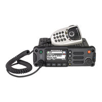
Motorola ASTRO APX 5500 User Manual (152 pages)
Brand:
Motorola
| Category:
Radio
| Size: 22.12 MB
Table of Contents
Control Head
1
Foreword
3
Parts Ordering
3
Computer Software Copyrights
3
Document Copyrights
3
Disclaimer
3
Trademarks
3
Installation Requirements for Compliance with Radio Frequency (RF) Energy Exposure Safety Standards
4
Table of Contents
5
Mobile Radio Model Numbering Scheme
15
Commercial Warranty
17
Limited Warranty
17
Motorola Communication Products
17
What this Warranty Covers and for How Long
17
II. General Provisions
17
III. State Law Rights
18
IV. How to Get Warranty Service
18
What this Warranty Does Not Cover
18
VI. Patent and Software Provisions
19
VII. Governing Law
19
Chapter 1 Introduction
21
Mobile Radio Description
21
Dimensions
21
Figure 1-1. Front View of APX 7500 MID Power Dash Mount Transceiver and Trunnion
21
Figure 1-2. Side View of APX 7500 MID Power Dash Mount Transceiver and Trunnion
21
Figure 1-3. Front View of APX 2500/4500 MID Power Dash Mount Transceiver and Trunnion
21
Figure 1-4. Side View of APX 2500/4500 MID Power Dash Mount Transceiver and Trunnion
21
Figure 1-5. Front View of APX 7500 High Power (100W) Transceiver and Trunnion
22
Figure 1-6. Side View of APX 7500 High Power (100W) Transceiver and Trunnion
22
Figure 1-7. Front View of O2 Control Head Attached to APX 7500 MID Power Dash Mount Transceiver
22
Figure 1-8. Side View of O2 Control Head Attached to APX7500 MID Power Dash Mount Transceiver
22
Figure 1-9. Front View of O7 Control Head Attached to APX 2500 MID Power Dash Mount Transceiver
22
Figure 1-10. Side View of O7 Control Head Attached to APX 2500 MID Power Dash Mount Transceiver
22
Figure 1-11. Front View of O3 Control Head with Coiled Cable
23
Figure 1-12. Side View of O3 Control Head with Coiled Cable
23
Figure 1-13. Front View of O2 Control Head with Remote Mount and Trunnion
23
Figure 1-14. Side View of O2 Control Head with Remote Mount and Trunnion
23
Figure 1-15. Front View of O5 Control Head with Remote Mount and Trunnion
23
Figure 1-16. Side View of O5 Control Head with Remote Mount and Trunnion
23
Figure 1-17. Front View of O7 Control Head with Remote Mount and Trunnion
24
Figure 1-18. Side View of O7 Control Head with Remote Mount and Trunnion
24
Figure 1-19. Front View of O9 Control Head with Trunnion
24
Figure 1-20. Side View of O9 Control Head with Trunnion
24
Figure 1-21. Top View of O9 Universal Relay Controller with Trunnion
24
Figure 1-22. Side View of O9 Universal Relay Controller with Trunnion
24
Standard Configurations
25
Dash Mount Configuration
25
Figure 1-23. Dash Mount Configuration for O2 Control Head
25
Figure 1-24. Dash Mount Configuration for O3 Control Head
25
Figure 1-25. Dash Mount Configuration for O5 Control Head (Only Applicable for ASTRO 25 Subscribers APX 5500/APX 6500/APX 7500/APX 6500 Li Mobile)
26
Figure 1-26. Dash Mount Configuration for O7 Control Head
26
Remote Mount Configuration
27
Figure 1-27. Remote Mount Configuration with MID Power Transceiver, Transceiver Interface Board, CHIB Rear Assembly and O2 Control Head
27
Figure 1-28. Remote Mount Configuration with MID Power Transceiver,Transceiver Interface Board
27
Figure 1-29. Remote Mount Configuration with MID Power Transceiver, Transceiver Interface Board, CHIB Rear Assembly and O5 Control Head
28
Figure 1-30. Remote Mount Configuration with MID Power Transceiver, Transceiver Interface Board, CHIB Rear Assembly and O7 Control Head
28
Figure 1-31. Remote Mount Configuration with MID Power Transceiver, Transceiver Interface Board and
28
Figure 1-32. Remote Mount Configuration with High Power (100W) Radio Transceiver and O2 Control
29
Figure 1-33. Remote Mount Configuration with High Power (100W) Radio Transceiver and O3 Control
29
Figure 1-34. Remote Mount Configuration with High Power (100W) Radio Transceiver and O5 Control
29
Figure 1-35. Remote Mount Configuration with High Power (100W) Radio Transceiver and O7 Control
30
Figure 1-36. Remote Mount Configuration with High Power (100W) Radio Transceiver and O9 Control
30
Figure 1-37. Remote Mount Configuration with MID Power Radio Transceiver, Universal Relay
31
Figure 1-38. Remote Mount Configuration with MID Power Radio Transceiver, Universal Relay
31
Figure 1-39. Remote Mount Configuration with High Power (100W) Radio Transceiver, Universal Relay Controller and O7 Control Head (URC Is Optional)
32
Figure 1-40. Remote Mount Configuration with High Power (100W) Radio Transceiver, Universal Relay Controller and O9 Control Head (URC Is Optional)
32
Multi Control Head
33
Motorcycle Configurations
34
Base/Control Stations
34
Tools Required for APX Mobile Installations
34
Chapter 2 Standard Configurations
35
Planning the Installation
35
Figure 2-1. Dash Mount Radios Can be Located in the Middle Console, on the Transmission Hump, or under the Dash
36
Figure 2-2. Remote Mount Radio Control Heads Can be Located in the Middle Console, on the Transmission Hump, or under the Dash
36
Figure 2-3. Remote Mount of the Radio, O9 Control Head and Universal Relay Controller
36
Figure 2-4. Radio Installation (O2 MID Power Dash Mount)
37
Figure 2-5. Radio Installation (O3 MID Power Dash Mount)
37
Figure 2-6. Radio Installation (O5 MID Power Dash Mount)
38
Figure 2-7. Radio Installation (O7 MID Power Dash Mount)
38
Figure 2-8. Radio Installation (O2 MID Power Remote Mount)
39
Figure 2-10. Radio Installation (O5 MID Power Remote Mount)
40
Figure 2-9. Radio Installation (O3 MID Power Remote Mount)
40
Figure 2-11. Radio Installation (O7 MID Power Remote Mount)
41
Figure 2-12. Radio Installation (O2 High Power Remote Mount)
41
Figure 2-13. Radio Installation (O3 High Power Remote Mount)
42
Figure 2-14. Radio Installation (O5 High Power Remote Mount)
42
Figure 2-15. Radio Installation (O7 High Power Remote Mount)
43
Figure 2-16. Radio Installation of O9 Remote Mount with Transceiver (URC Is Optional)
43
Figure 2-17. Radio Installation (O9 Remote Mount with Pinouts)
44
Figure 2-18. Remote Control Head Pinouts
44
Radio Operation Wiring for Dash and Remote Configurations
48
2.1.3.1 Dash Mount: Power, Ignition, and Emergency Cable Installation
48
2.1.3.2 Remote Mount: Power, Ignition, and Emergency Cable Installation
49
Table 2-1. Dash O2, O3, O5, O7 or O9 Radio Operations Dependent Upon A+ and
50
Table 2-2. Remote O2, O3, O5, O7 or O9 Radio Operations Dependent Upon A+ and
50
Table 2-3. Remote O2, O3, O5, O7 or O9 Radio Operations Dependent Upon A+ and
50
Ignition Sense Switch (Radio Wide Advance)
51
Table 2-4. Ignition Sense Switch Settings in CPS
51
Siren/Pa Configuration/Programming
52
Table 2-5. Power Level Configurations
52
Radio Mounting
53
Figure 2-22. APX 7500/ APX6500/ APX5500/ Apx6500Li MID Power Trunnion Orientation
53
Figure 2-23. APX 2500/APX4500 MID Power Trunnion Orientation
54
Figure 2-24. Trunnion Orientation for 100W Radios
54
Table 2-6. MID Power Trunnion Kit
55
Figure 2-25. Transmission Hump Trunnion Mounting
56
Figure 2-26. below Dash Trunnion Mounting
56
Remote Mount with Trunnion
57
2.2.2.1 100W Radios Only
58
2.2.2.2 Remote Mount Control Head Installation
58
Figure 2-27. 100W Radio Mounting into Quick Release Trunnion
58
Figure 2-28. O5 Control Head Installation Exploded View
59
Figure 2-29. O9 Control Head Installation Exploded View
60
Figure 2-30. O5 Control Head Rear View (also Applicable for O2 and O7 Control Heads)
60
2.2.2.3 Multiple Control Head Installation
61
Figure 2-31. O9 Control Head Rear View
61
Figure 2-32. Multiple Control Heads Example Configurations
62
Table 2-7. Available CAN Cables
62
2.2.2.4 Cable Installation
63
2.2.2.5 Setting the Initial Control Head ID
63
Figure 2-33. APX Mobile O5 Control Head Front View
63
Figure 2-34. Radio Display with Current Control Head ID
63
Table 2-8. Ignition Interface Cables
63
2.2.2.6 O3 Control Head and Remote Mount Cabling
64
Figure 2-35. APX Mobile O5 Control Head Front View - Mode Knob
64
Figure 2-36. O3 Control Head
64
Figure 2-37. O3 Control Head Rear View
65
Figure 2-38. Hang-Up Clip Installation Exploded View
65
Locking Kit (Optional)
66
2.2.3.1 All Radios Except 100W
66
2.2.3.2 100W Radios
66
Figure 2-39. Locking Kit (Optional) (Cannot be Used for 100W Radios)
66
Figure 2-40. Lock Supplied with 100W Quick Release Trunnion
66
Power Cables (Transceiver and Control Head)
67
Optional Locking Feature for High Power Chassis Power Cables
67
Figure 2-41. Bracket Installation
67
Table 2-9. Power Cables
67
Figure 2-42. Bracket Installation
68
Figure 2-43. Bracket Installation (Assembled State)
68
Figure 2-44. Bracket Uninstallation
69
Figure 2-45. Bracket Uninstallation
69
O2, O3, O5, O7 or O9 Control Head Power Cables
70
Figure 2-46. HKN6188_ Power Cable with External Speaker Connector
70
Figure 2-47. HKN6187_ Power Cable with External Speaker Connector, Record Audio Output Jack (2.5 MM) and Earphone Jack (2.5 MM)
70
Battery Selector Switch
71
Figure 2-48. Battery Selector Switch
71
Antenna Installation
72
Selecting an Antenna Site/Location on a Metal Body Vehicle
72
Figure 2-49. Multiple Antennas Separation
73
Mini-UHF Connection
74
Figure 2-50. Mini-UHF Connection (as Shown on MID Power)
74
Figure 2-51. Mini-UHF Connection (100W Radios Only)
74
Figure 2-52. Mini-UHF Connector Tool (as Shown on MID Power)
75
Figure 2-53. Mini-UHF Connector Tool (100W Radios Only)
75
GPS Antenna Placement
76
GPS Connection
76
Figure 2-54. GPS Antenna Connector on the Back of the MID Power Radio
76
Figure 2-55. GPS Antenna Connector on the Front of the 100W Radio
76
Speaker
77
Figure 2-56. Speaker Mounting
77
Figure 2-57. Removing the Screws on the Control Head
78
Figure 2-58. Removing the Control Head
78
Internal Speaker Disassembly
78
Figure 2-59. Disconnecting the Speaker Connector
79
Figure 2-60. Reattaching the Control Head
79
Microphone Hang-Up Clip
80
Standard or O3 Control Head Hang-Up Clip
80
RFID (Option)
80
Figure 2-61. RFID Location on MID Power Radio
80
Figure 2-62. RFID Location on APX 2500/APX 4500 MID Power Radio
80
Figure 2-63. RFID Location on High Power Radio
81
Figure 2-64. Read Angle for MID Power Radio
82
Figure 2-65. Tag Angle for MID Power Radio
82
RFID Reading
82
Figure 2-66. Read Angle for APX 2500/APX 4500 MID Power Radio
83
Figure 2-67. Tag Angle for APX 2500/APX 4500 MID Power Radio
83
Figure 2-68. Read Angle for High Power Radio
83
Figure 2-69. Tag Angle for High Power Radio
84
Figure 2-70. Examples of Reader and Tag Aligned (Reader Orientation)
84
Figure 2-71. Example of Reader and Tag Misaligned (Reader Orientation)
84
Programming RFID (if Equipped)
85
Table 2-10. Model Number Chart in 12-Digit ASCII Format
85
Table 2-11. Serial Number with Radio Band/Tier/Power
85
Completing the Installation
86
Chapter 3 Universal Relay Controller Installation
87
Universal Relay Controller Mounting
87
Figure 3-1. Universal Relay Controller Orientation
87
Figure 3-2. Universal Relay Controller Installation Exploded View
88
O7/O9 Universal Relay Controller Cable Assembly
89
Power Cable
89
Ground Cable
89
Figure 3-3. Power and Ground Cable Glands
89
Wires
90
Figure 3-4. Cable Gland Assembly with Gasket
90
Figure 3-5. Wires Installation
90
O7/O9 to URC Cable
91
Figure 3-6. Wire Installation with Black Stick
91
Figure 3-7. O7/O9 to URC Cable Installation
91
Chapter 4 Options and Accessories Installation
93
Dash-Mount Accessory Installation
93
Dash-Mount Emergency Pushbutton or Footswitch Installation
93
Figure 4-1. Emergency Switch Wiring Diagram
93
Dash-Mount Horn and Lights (External Alarms) Relays
94
Remote-Mount Accessory Installation
94
Figure 4-2. Horn/Light Wiring Diagram
94
Emergency Pushbutton or Footswitch Installation
95
Figure 4-3. Emergency Jumper Removal in Remote Mount
95
Figure 4-4. Gunlock Switch Redundancy Diagram
96
Gunlock Installation
96
Horn (External Alarm) Relay Installation
96
Lights (External Alarm) Relay Installation
96
Earphone Jack
97
Figure 4-5. Siren/Pa Horn-Ring Connections
97
Horn-Ring Transfer
97
Record Audio out Jack of Transmit and Receive Audio
97
RS232 Cables
98
USB Data Cables
98
Vehicle Interface Port Overview
98
Figure 4-6. Remote Control Head Pinouts
98
Figure 4-7. HKN6196_ VIP Connector Detail
98
Figure 4-8. Relay Coil
99
Table 4-1. VIP Output Connections
99
VIP Output Connections
99
Table 4-2. VIP Input Connections
100
VIP Input Connections
100
Compatibility of Emergency When Attaching a Siren
101
Figure 4-9. Field Adjustment for Emergency Operation with Siren Accessory
101
Figure 4-10. Location for Pin 8
101
Accessory Connector Assembly Details (P2) (All Models Except 100W)
102
Disassembly and Assembly
102
Disassembly
102
4.5.1.2 Assembly
103
Figure 4-11. Exploded View of Accessory Connector Assembly (HLN6863_)
103
Adapter Cable
104
Memory and Three-Day Secure Key Retention Option
104
Figure 4-12. Rear Accessory Connector Audio Configuration
104
Figure 4-13. Rear Accessory Connector Data Configuration
104
Chapter 5 Motorcycle Radio Installation
105
Motorcycle Radio Description
105
Transceiver Enclosure
105
Control/Display Unit
105
Figure 5-1. Identification of a Motorcycle Radio by Using a Label
105
Control Head Cable
106
Microphone
106
Keypad MIC
106
External Speaker
106
Headset Capability
106
Antenna
106
Ignition Sense (ACC) Wire
106
Installation Overview
107
General
107
Important Installation Hints
108
Parts Identification
109
Order of Installation
109
Installing the Universal Mounting Plate
110
Figure 5-2. Universal Mounting Plate Installation (Part of Radio Enclosure Kit)
110
Installing the Speaker and Control Head
111
Figure 5-3. Motorcycle Control Head Cabling (3075217A01)
111
Figure 5-4. Handlebar Installation with Speaker and Control Head Mounted Together
112
Handlebar Installation with Speaker and Control Head Mounted Together
112
Fuel Tank Console Installation with Speaker and Control Head Mounted Together
113
Figure 5-5. Fuel Tank Console Installation with Speaker and Control Head Mounted Together
114
Handlebar Installation with Speaker and Control Head Mounted Separately
115
Figure 5-6. Handlebar Installation with Speaker and Control Head Mounted Separately
116
Fuel Tank Console Installation with Speaker and Control Head Mounted Separately
116
Figure 5-7. Fuel Tank Console Installation with Speaker and Control Head Mounted Separately
117
Installing the Speaker
118
Installing the Microphone Hang-Up Clip
118
Extension Bracket Mounting
118
Speaker/Control Head Bracket Side Mounting
118
Other Hang-Up Clip Mounting
119
Installing Antenna Base and Cables
119
Figure 5-8. Location of Band 1 or Band 2 (Depending on the Antenna Port They Align To)
119
Figure 5-9. Antenna Band Identification
120
Figure 5-10. APX 2500/APX 4500 Antenna Band Identification
120
Figure 5-11. Routing the Coaxial Cable for GPS
121
Installing the Antenna
122
Cable Routing
122
Figure 5-13. Routing the Coaxial Cable for Band 2
122
Figure 5-14. Cable Routing
123
Installing the Weather-Resistant Enclosure
125
Figure 5-15. Weather-Resistant Enclosure Installation
125
5.11 Transceiver and Cabling Installation
126
5.11.1 Installing Cabling in the Enclosure
126
5.11.2 Installing the Transceiver
127
Figure 5-16. Installing Cables
127
Figure 5-17. Installing the Transceiver
128
Table 5-1. Transceiver Installation Parts List
128
5.12 Installing the Emergency Switch Option
129
5.13 Installing the External Alarm Relay Option
129
5.14 Installing the Headset Accessory
129
Figure 5-18. Motorcycle Wiring Harness Rework
129
5.15 Installing the O5 Control Head Sunshield
130
Figure 5-19. Remote Mount Trunnion with Sunshield
130
Figure 5-20. Position the Sunshield
130
Figure 5-21. Slide the Control Head Onto Trunnion
131
Figure 5-22. Position Control Head as Desired
131
5.16 Horn/Lights Wiring
132
5.17 Emergency Switch Wiring
132
Figure 5-23. Horn/Lights Wiring Diagram
132
Figure 5-24. Emergency Switch Wiring Diagram
132
Chapter 6 Finishing the Installation
133
Cable Connection
133
O2 Control Head
133
O3 Control Head
133
O5 Control Head
133
O7 Control Head
134
O9 Control Head
134
Dust Cover Installation
135
Figure 6-1. Dust Cover Installation Locations
135
Miscellaneous Information
136
Chapter 7 Best Practices: Installation & Troubleshooting
137
Check Wiring of Ignition and Radio Ignition Sensing
137
Check Physical Installation of Radio Ground and Radio Accessory Wiring
138
Improve the Electrical Quality of the Power and Ignition Lines
138
Minimize the Effect of Poorly Grounded Antennas
139
Jump-Start the Vehicle
139
Eliminate Noise/Howling from PA Speaker
139
Appendix A Replacement Parts Ordering
141
Basic Ordering Information
141
Motorola Online
141
Mail Orders
141
Fax Orders
142
Parts Identification
142
Product Customer Service
142
Asia Pacific Service Centers
142
Advertisement
Motorola ASTRO APX 5500 User Manual (139 pages)
TWO-WAY RADIOS
Brand:
Motorola
| Category:
Radio
| Size: 1.59 MB
Table of Contents
Table of Contents
2
Declaration of Conformity
10
Important Safety Information
11
Notice to Users (FCC and Industry Canada)
12
Software Version
13
Computer Software Copyrights
14
Documentation Copyrights
15
Disclaimer
16
Read Me First
17
Notations Used in this Manual
17
Radio Maintenance
17
Radio Care
17
Cleaning the External Surface of the Radio
18
Additional Performance Enhancement
19
ASTRO 25 Enhanced Data
19
Dynamic System Resilience (DSR)
19
Crosstalk Prevention
19
Encrypted Integrated Data (EID)
19
Securenet
19
Over-The-Air Rekeying
19
P25 Digital Vehicular Repeater System (DVRS)
19
Conventional Talkgroup and Radio Scan Enhancements
20
What Your Dealer/System Administrator Can Tell You
20
Preparing Your Radio for Use
21
Turning on the Radio
21
Adjusting the Volume
22
Validating Compatibility During Power up
22
Radio Controls
23
Control Head and Microphone
23
Programmable Features
24
Assignable Radio Functions
24
Assignable Settings or Utility Functions
26
Accessing the Preprogrammed Functions
26
Menu Select Buttons
26
Home Button
27
4-Way Navigation Button
27
Data Feature Button
27
Volume Rocker
27
Mode Rocker
27
Keypad
27
Keypad Characters - Uppercase Mode
27
Keypad Characters - Lowercase Mode
28
Keypad Characters - Numeric Mode
29
Keypad Characters - Hexadecimal Mode
30
Push-To-Talk (PTT) Button
31
Status Indicators
32
Status Icons
32
Text Messaging Service (TMS) Indicators
34
TMS Status Icons
34
TMS Menu Options
35
LED Indicator
36
Intelligent Lighting Indicators
37
Alert Tones
37
Phone Call Displays and Alerts
39
General Radio Operation
40
Selecting a Zone
40
Selecting a Radio Channel
40
Selecting a Channel by Using Channel Search Button
41
Mode Select Feature
41
Saving a Zone and a Channel to a Softkey
41
Saving a Zone and a Channel to a Button
42
Receiving and Responding to a Radio Call
42
Receiving and Responding to a Talkgroup Call
42
Receiving and Responding to a Private Call (Trunking Only)
43
Receiving and Responding to a Telephone Call (Trunking Only)
43
Methods to Make a Radio Call
44
Making a Talkgroup Call
44
Making a Private Call (Trunking Only)
45
Making a Telephone Call (Trunking Only)
45
Switching between Repeater or Direct Operation Button
46
Monitor Feature
46
Monitoring a Channel
46
Monitoring Conventional Mode
47
Advanced Features
48
Viqi
48
Using Viqi Virtual Partner
49
Advanced Call Features
49
Calling a Phone Not in the List
49
Selective Call (ASTRO Conventional Only)
49
Receiving a Selective Call
49
Making a Selective Call
50
Talkgroup Call Feature (Conventional Operation Only)
50
Selecting a Talkgroup
51
Sending a Status Call
51
Making a Priority Dispatch Calls
52
Dynamic Regrouping (Trunking Only)
52
Requesting a Reprogram (Trunking Only)
52
Classification of Regrouped Radios
53
Dynamic Zone Programming (DZP)
53
Entering the Dynamic Zone to Select a Dynamic Channel
53
Deleting a Channel in the Dynamic Zone
54
Saving a Channel in the Dynamic Zone from List Selection
54
Contacts
55
Making a Private Call from Contacts
55
Adding a New Contact Entry
56
Deleting a Contact Entry
56
Adding a Contact to a Call List
57
Methods of Contact Editing in a Call List
57
Editing an Entry Alias
57
Editing a Call Type
58
Editing as Entry ID
58
Scan Lists
59
Intelligent Priority Scan
59
Viewing a Scan List
59
Editing the Scan List
59
Changing the Scan List Status
60
Viewing and Changing the Priority Status
60
Scan
61
Turning Scan on or off
61
Turning Scan on While Disregarding the Squelch Code (Conventional Channels Only)
61
Transmitting While the Scan Is on
61
Transmitting Using Radio Programmed for Talkback Scan
61
Transmitting Using Radio Programmed for Non-Talkback Scan
62
Deleting a Nuisance Channel
62
Restoring a Nuisance Channel
62
Changing Priorities Status While Scan Is on
62
Restoring Priorities in a Scan List
63
Using the Hang up Box (HUB)
63
Call Alert Paging
63
Receiving a Call Alert Page
64
Sending a Call Alert Page
64
Enabling and Disabling In-Call User Alert
65
Quick Call II (ASTRO P25 Digital Trunking and Conventional)
65
Initiating a Quick Call II Transmission
66
Emergency Operation
66
Exiting Emergency
66
Exiting Emergency as Supervisor (Trunking Only)
67
Sending an Emergency Alarm
67
Sending an Emergency Call (Trunking Only)
68
Sending an Emergency Call with Hot MIC (Trunking Only)
68
Sending an Emergency Alarm with Emergency Call
68
Sending an Emergency Alarm and Call with Hot MIC
69
Sending a Silent Emergency Alarm
69
Special Considerations for Emergencies
70
Impact Detection
70
Detecting Impact
71
Exiting Impact Detected Condition
71
Post-Alert Timer
71
Triggering Emergency
71
Re-Initiating Impact Detection Sequence
72
Automatic Registration Service (ARS)
72
Selecting or Changing the ARS Mode
72
User Login Feature
73
Logging in as a User
73
Logging out
74
Text Messaging Service (TMS)
74
Accessing the Messaging Features
75
Composing and Sending a New Text Message
75
Sending a Quick Text Message
76
Priority Status and Request Reply of a New Text Message
77
Appending a Priority Status to a Text Message
77
Appending a Priority Status and a Reply Request to a Text Message
78
Appending a Request Reply to a Text Message
78
Removing a Priority Status from a Text Message
78
Removing a Request Reply from a Text Message
78
Receiving a Text Message
79
Removing a Priority Status and a Reply Request from a Text Message
79
Viewing a Text Message from the Inbox
79
Replying to a Received Text Message
80
Accessing the Drafts Folder
81
Sent Text Messages
81
Deleting Text Messages
82
Secure Operations
83
Accessing the Secure Feature
83
Enabling Secure Transmission
83
Loading Encryption Keys
83
Managing Encryption
83
Multikey Feature
84
Selecting Encryption Keys
84
Erasing Encryption Keys
85
Selecting Keysets
85
Hear Clear
86
Infinite UKEK Retention
86
MDC Over-The-Air Rekeying Page (Conventional Only)
86
Requesting an Over-The-Air Rekey
86
Radio Lock
87
Changing the Radio Lock Password
87
Enabling or Disabling Radio Lock (Secure Radios Only)
87
Changing the Tactical Inhibit Password
88
Radio Stun and Kill
89
Radio Kill
89
Radio Stun
89
Using Radio Stun
89
Using Direct Kill to Kill Your Own Radio
90
Using Remote Kill to Kill Another Radio
90
Radio Inhibit
90
Global Positioning System/Global Navigation Satellite System
91
GPS Operation
91
GPS Performance Enhancement
91
Accessing the Outdoor Location Feature
92
Location Format
92
The Outdoor Location Feature (Using GPS)
92
Turning off GPS
93
Saving a Waypoint
93
Viewing a Saved Waypoint
94
Editing the Alias of a Waypoint
94
Editing the Coordinates of a Waypoint
95
Deleting a Single Saved Waypoint
96
Deleting All Saved Waypoints
96
Measuring the Distance and Bearing from a Saved Waypoint
97
Location Feature in Emergency Mode
97
Peer-Location on the Display (ASTRO Conventional Only)
97
Geofence (ASTRO 25 Trunking System)
98
Entering the Geofence Area
98
Mission Critical Geofence
99
Entering Mission Critical Geofence
99
Exiting Mission Critical Geofence
100
Trunking System Controls
100
Operating in Failsoft System
100
Out-Of-Range Radio
100
Smartconnect
101
Smartzone
101
Site Trunking Feature
101
Locking and Unlocking a Site
101
Site Display and Search Button
102
Changing the Current Site
102
Viewing the Current Site
102
Trunked Announcement
102
Initiating an Announcement
103
Ignition Switch Options
103
Blank
103
Tx Inhibit
103
PTT Tx Inhibit
103
Required
104
Soft Power off
104
Ignition Only Power up
104
Using Emergency Power up
104
Auto Power off Timer
104
Voice Announcement
105
Site Selectable Alerts (ASTRO 25)
105
Sending SSA Notification to Single Site
106
Sending SSA Notification to Single Site by Manual Entry
106
Sending SSA Notification to All Available Sites
107
Sending SSA Notification to All Sites
107
Stopping SSA Notification of a Single Site
108
Stopping SSA Notification of a Single Site by Manual Entry
108
Stopping SSA Notification of All Sites
109
Stopping SSA Notification of All Available Sites
110
Channel Change on off Hook on All Channels
110
Low Voltage Threshold Warning
111
Wi-Fi
111
Turning Wi-Fi on or off
111
Checking the Wi-Fi Configuration and Status of the Radio
112
Selecting Wifi Network
112
Utilities
113
Selecting the Power Level
113
Viewing Recent Calls
113
Controlling the Display Backlight
114
Selecting a Radio Profile
114
Turning the Keypad Tones on or off
115
Turning Voice Mute on or off
115
Using the Time-Out Timer
115
Analog Options
116
Using Conventional Squelch Operation Features
116
Digital Options
117
Digital PTT ID Support
117
Smart PTT (Conventional Only)
117
Using the PL Defeat Feature
117
Enabling Transmit Inhibition
118
Transmit Inhibit
118
Disabling Transmit Inhibition
119
Instant Recall
119
Saving and Playback Calls
119
Accessing the Radio Information
120
General Radio Information
120
Viewing the IP Information
121
External Alarms (Horn and Lights)
122
Viewing the Control Assignments
122
Changing the Selected Alarms
123
Receiving a Call While Alarms Are Turned on
123
Using Non-Permanent Horn and Lights
123
Using Permanent Horn and Lights
123
Entering the Front Panel Programming Mode
124
Front Panel Programming
124
Turning off Non-Rearmable External Alarms
124
Turning off Rearmable External Alarms
124
Editing FPP Mode Parameters
125
Accessories
126
Maritime Radio Use in the VHF Frequency Range
127
Special Channel Assignments
127
Emergency Channel
127
Non-Commercial Call Channel
127
Operating Frequency Requirements
127
Declaration of Compliance for the Use of Distress and Safety Frequencies
130
Technical Parameters for Interfacing External Data Sources
130
Glossary
131
Status Calls
135
Limited Warranty
136
Motorola Solutions Communication Products
136
What this Warranty Covers and for How Long
136
II. General Provisions
137
III. State Law Rights
137
IV. How to Get Warranty Service
137
What this Warranty Does Not Cover
137
VI. Patent and Software Provisions
138
VII. Governing Law
139
VIII. for Australia Only
139
Service
139
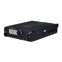
Motorola ASTRO APX 5500 User Manual (128 pages)
MOBILE O5 CONTROL HEAD
Brand:
Motorola
| Category:
Two-Way Radio
| Size: 0.88 MB
Table of Contents
Table of Contents
2
List of Tables
9
Software Version
10
Read Me First
11
Notations Used in this Manual
11
Radio Care
11
Cleaning the External Surface of the Radio
12
Additional Performance Enhancement
12
ASTRO 25 Enhanced Data
12
Dynamic System Resilience
12
Crosstalk Prevention
13
Encrypted Integrated Data
13
Securenet
13
Over-The-Air Rekeying
13
P25 Digital Vehicular Repeater System
13
Conventional Talkgroup and Radio Scan Enhancements
14
What Your Dealer/System Administrator Can Tell You
14
Preparing Your Radio for Use
15
Turning on the Radio
15
Adjusting the Volume
15
Validating Compatibility During Power up
16
Radio Controls
17
O5 Control Head and Microphone
17
Table 1: O5 Control Head and Microphone
17
Keypad
19
Table 2: Text Entry Modes
19
Table 3: Keypad Characters
19
Programmable Features
20
Assignable Radio Functions
20
Assignable Settings or Utility Functions
22
Status Indicators
24
LED Indications
24
Status Icons
24
Table 4: LED Indications
24
TMS Status Icons
27
Call Type Icons
27
Table 5: TMS Status Icons
27
Table 6: Call Type Icons
27
Intelligent Lighting Indicators
28
Alert Tones
28
General Radio Operation
31
Selecting a Zone
31
Selecting a Radio Channel
31
Selecting a Channel by Using Channel Search Button
31
Mode Select Feature
32
Saving a Zone and a Channel to a Softkey
32
Saving a Zone and a Channel to a Button
32
Receiving and Responding to a Radio Call
33
Receiving and Responding to a Talkgroup Call
33
Receiving and Responding to a Private Call (Trunking Only)
34
Receiving and Responding to a Telephone Call (Trunking Only)
34
Methods to Make a Radio Call
34
Making a Talkgroup Call
35
Making a Private Call (Trunking Only)
35
Making a Telephone Call (Trunking Only)
36
Switching between Repeater or Direct Operation Button
36
Monitor Feature
37
Monitoring a Channel
37
Monitoring Conventional Mode
37
Advanced Features
38
Viqi
38
Table 7: Viqi Virtual Partner Queries
38
Using Viqi Virtual Partner
39
Advanced Call Features
39
Calling a Phone Not in the List
39
Selective Call (ASTRO Conventional Only)
39
Receiving a Selective Call
39
Making a Selective Call
40
Talkgroup Call Feature (Conventional Only)
40
Selecting a Talkgroup
41
Sending a Status Call
41
Making a Priority Dispatch Calls
42
Dynamic Regrouping (Trunking Only)
42
Classification of Regrouped Radios
42
Requesting a Reprogram (Trunking Only)
43
Dynamic Zone Programming
43
Entering the Dynamic Zone to Select a Dynamic Channel
43
Deleting a Channel in the Dynamic Zone
44
Saving a Channel in the Dynamic Zone from List Selection
44
Multiple Control Head Features
44
Setting the ID of the Initial Control Head
45
All Active Mode
45
Activating and Deactivating Intercom in All Active Mode
45
One Active Mode
46
Contacts
47
Making a Private Call from Contacts
47
Adding a New Contact Entry
48
Deleting a Contact Entry
48
Adding a Contact to a Call List
49
Methods of Contact Editing in a Call List
49
Editing an Entry Alias
49
Editing a Call Type
50
Editing as Entry ID
50
Scan Lists
50
Intelligent Priority Scan
51
Viewing a Scan List
51
Editing the Scan List
51
Changing the Scan List Status
52
Viewing and Changing the Priority Status
52
Scan
53
Turning Scan on or off
53
Turning Scan on While Disregarding the Squelch Code (Conventional Channels Only)
53
Deleting a Nuisance Channel
53
Restoring a Nuisance Channel
54
Changing Priorities Status While Scan Is on
54
Restoring Priorities in a Scan List
54
Using the Hang up Box (HUB)
54
Call Alert Paging
55
Receiving a Call Alert Page
55
Sending a Call Alert Page
55
Enabling and Disabling In-Call User Alert
56
Quick Call II
57
Initiating a Quick Call II Transmission
57
Emergency Operation
57
Special Considerations for Emergency Operation
58
Emergency Keep-Alive
58
Exiting Emergency Operation
58
Exiting Emergency as Supervisor (Trunking Only)
58
Table 8: Emergency Operation Scenarios
58
Sending an Emergency Alarm
59
Sending an Emergency Call (Trunking Only)
59
Sending an Emergency Call with Hot MIC (Trunking Only)
60
Sending an Emergency Alarm with Emergency Call
60
Sending an Emergency Alarm and Call with Hot MIC
61
Sending a Silent Emergency Alarm
61
Impact Detection
62
Detecting Impact
62
Exiting Impact Detected Condition
63
Automatic Registration Service
63
Selecting or Changing the ARS Mode
63
User Login Feature
64
Logging in as a User
64
Logging out
65
Text Messaging Service
66
Accessing the Messaging Features
66
Composing and Sending a New Text Message
66
Sending a Quick Text Message
67
Priority Status and Request Reply of a New Text Message
68
Appending a Priority Status to a Text Message
68
Removing a Priority Status from a Text Message
68
Appending a Priority Status and a Reply Request to a Text Message
69
Appending a Request Reply to a Text Message
69
Removing a Priority Status and a Reply Request from a Text Message
69
Removing a Request Reply from a Text Message
69
Receiving a Text Message
70
Viewing a Text Message from the Inbox
70
Accessing the Drafts Folder
71
Replying to a Received Text Message
71
Sent Text Messages
72
Deleting Text Messages
73
Secure Operations
73
Enabling Secure Transmission
73
Accessing the Secure Feature
73
Managing Encryption
74
Loading Encryption Keys
74
Multikey Feature
74
Selecting Encryption Keys
75
Selecting Keysets
75
Erasing Encryption Keys
76
MDC OTAR (Conventional Only)
76
Requesting an Over-The-Air Rekey
76
Hear Clear
77
Infinite UKEK Retention
77
Radio Lock
77
Changing the Radio Lock Password
78
Enabling or Disabling Radio Lock (Secure Radios Only)
78
Changing the Tactical Inhibit Password
79
Radio Stun and Kill
79
Radio Stun
79
Using Radio Stun
79
Radio Kill
80
Using Remote Kill to Kill Another Radio
80
Using Direct Kill to Kill Your Own Radio
81
Radio Inhibit
81
Global Positioning System/Global Navigation Satellite System
81
GPS Performance Enhancement
81
Accessing the Outdoor Location Feature
82
Location Format
82
The Outdoor Location Feature (Using GPS)
82
Saving a Waypoint
83
Turning off GPS
83
Editing the Alias of a Waypoint
84
Viewing a Saved Waypoint
84
Editing the Coordinates of a Waypoint
85
Deleting a Single Saved Waypoint
86
Deleting All Saved Waypoints
86
Location Feature in Emergency Mode
87
Measuring the Distance and Bearing from a Saved Waypoint
87
Peer-Location on the Display (ASTRO Conventional)
87
Mission Critical Geofence (ASTRO 25 Trunking)
88
Entering the Geofence Area
88
Entering Mission Critical Geofence
89
Exiting Mission Critical Geofence
89
Mission Critical Geofence
89
Trunking System Controls
90
Operating in Failsoft System
90
Out-Of-Range Radio
90
Smartconnect
90
Site Trunking Feature
91
Smartzone
91
Locking and Unlocking a Site
91
Viewing the Current Site
92
Changing the Current Site
92
Trunked Announcement
92
Initiating an Announcement
92
Ignition Switch Options
93
Using Emergency Power up
93
Voice Announcement
94
Site Selectable Alerts (ASTRO 25 Trunking)
94
Sending SSA Notification to Single Site
94
Sending SSA Notification to Single Site by Manual Entry
95
Sending SSA Notification to All Sites
95
Sending SSA Notification to All Available Sites
96
Stopping SSA Notification of a Single Site
97
Stopping SSA Notification of a Single Site by Manual Entry
97
Stopping SSA Notification of All Sites
98
Stopping SSA Notification of All Available Sites
98
Channel Change on Off-Hook
99
Low Voltage Threshold Warning
99
Wi-Fi
100
Turning Wi-Fi on or off
100
Selecting Wifi Network
100
Checking the Wi-Fi Configuration and Status of the Radio
101
Utilities
101
Viewing Recent Calls
101
Selecting the Power Level
102
Selecting a Radio Profile
102
Controlling the Display Backlight
103
Turning the Keypad Tones on or off
103
Turning Voice Mute on or off
103
Using the Time-Out Timer
104
Conventional Squelch Operation
104
Using Conventional Squelch Operation Features
105
Using the PL Defeat Feature
105
Digital PTT ID Support
105
Smart PTT (Conventional Only)
106
Transmit Inhibit
106
Enabling Transmit Inhibition
106
Disabling Transmit Inhibition
107
Instant Recall
107
Saving and Playback Calls
107
Changing the Selected Alarms
109
External Alarms (Horn and Lights)
109
Using Non-Permanent Horn and Lights
109
Using Permanent Horn and Lights
109
Receiving a Call While Alarms Are Turned on
110
Turning off Non-Rearmable External Alarms
110
Turning off Rearmable External Alarms
110
Accessories
111
Legal and Compliance Statement
112
Disclaimer
112
Copyrights
112
Declaration of Conformity
113
Important Safety Information
114
Notice to Users (FCC)
114
FCC Licensing Information
114
Canada Licensing Information
115
Maritime Radio Use in the VHF Frequency Range
116
Special Channel Assignments
116
Emergency Channel
116
Non-Commercial Call Channel
116
Operating Frequency Requirements
116
Table 9: VHF Marine Channel List
117
Declaration of Compliance for the Use of Distress and Safety Frequencies
119
Technical Parameters for Interfacing External Data Sources
119
Limited Warranty
120
Motorola Solutions Communication Products
120
What this Warranty Covers and for How Long
120
II. General Provisions
121
III. State Law Rights
121
IV. How to Get Warranty Service
121
What this Warranty Does Not Cover
121
VI. Patent and Software Provisions
122
VII. Governing Law
123
VIII. for Australia Only
123
Service
123
Advertisement
Advertisement
Related Products
Motorola ASTRO APX O5
Motorola ASTRO APX O7
Motorola ASTRO APX O3
Motorola APX 7500 O5
Motorola APX7500 03
Motorola APX8500
Motorola ASTRO APX 6500
Motorola ASTRO APX 6500 Li
Motorola APX 2500
Motorola APX 4000 2
Motorola Categories
Cell Phone
Two-Way Radio
Baby Monitor
Cordless Telephone
Radio
More Motorola Manuals
Login
Sign In
OR
Sign in with Facebook
Sign in with Google
Upload manual
Upload from disk
Upload from URL