Sign In
Upload
Manuals
Brands
Motorola Manuals
Radio
APX7500 03
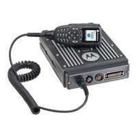
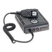
Motorola APX7500 03 Manuals
Manuals and User Guides for Motorola APX7500 03. We have
2
Motorola APX7500 03 manuals available for free PDF download: Installation Manual, User Manual
Motorola APX7500 03 Installation Manual (142 pages)
Two-Way Radios
Brand:
Motorola
| Category:
Radio
| Size: 28.47 MB
Table of Contents
Computer Software Copyrights
3
Disclaimer
3
Document Copyrights
3
Foreword
3
Parts Ordering
3
Product Safety and RF Exposure Compliance
3
Trademarks
3
Installation Requirements for Compliance with Radio Frequency (RF) Energy Exposure Safety Standards
4
Table of Contents
5
Mobile Radio Model Numbering Scheme
13
Commercial Warranty
15
II. General Provisions
15
Limited Warranty
15
Motorola Communication Products
15
What this Warranty Covers and for How Long
15
III. State Law Rights
16
IV. How to Get Warranty Service
16
What this Warranty Does Not Cover
16
VI. Patent and Software Provisions
17
VII. Governing Law
17
Chapter 1 Introduction
19
Mobile Radio Description
19
Dimensions
19
Figure 1-1. Front View of MID Power Dash Mount Transceiver and Trunnion
19
Figure 1-2. Side View of MID Power Dash Mount Transceiver and Trunnion
19
Figure 1-3. Front View of High Power (100W) Transceiver and Trunnion
19
Figure 1-4. Side View of High Power (100W) Transceiver and Trunnion
19
Figure 1-5. Front View of O3 Control Head with Coiled Cable
20
Figure 1-6. Side View of O3 Control Head with Coiled Cable
20
Figure 1-7. Front View of O5 Control Head with Trunnion
20
Figure 1-8. Side View of O5 Control Head with Trunnion
20
Figure 1-9. Front View of O9 Control Head with Trunnion
20
Figure 1-10. Side View of O9 Control Head with Trunnion
20
Figure 1-11. Top View of O9 Universal Relay Controller with Trunnion
21
Figure 1-12. Side View of O9 Universal Relay Controller with Trunnion
21
Standard Configurations
22
Dash Mount Configuration
22
Figure 1-13. Dash Mount Configuration with O5 Control Head
22
Figure 1-14. Dash Mount Configuration with Transceiver Interface Board and O3 Control Head
22
Remote Mount Configuration
23
Figure 1-15. Remote Mount Configuration with MID Power Transceiver and O5 Control Head
23
Figure 1-16. Remote Mount Configuration with MID Power Transceiver, Transceiver Interface Board
23
Figure 1-17. Remote Mount Configuration with High Power (100W) Radio Transceiver
24
Figure 1-18. Remote Mount Configuration with High Power (100W) Radio Transceiver
24
Figure 1-19. Remote Mount Configuration with Radio Transceiver and O9 Control Head
24
Multi Control Head
25
Figure 1-20. Remote Mount Configuration with MID Power Radio Transceiver, Universal Relay Controller and O9 Control Head (URC Is Optional.)
25
Figure 1-21. Remote Mount Configuration with High Power (100W) Radio Transceiver, Universal Relay Controller and O9 Control Head (URC Is Optional.)
25
Motorcycle Configurations
26
Base/Control Stations
26
Tools Required for APX 7500 Installations
26
Chapter 2 Standard Configurations
27
Planning the Installation
27
Figure 2-1. Dash Mount Radios Can be Located in the Middle Console, on the Transmission Hump, or under the Dash
28
Figure 2-2. Remote Mount Radio Control Heads Can be Located in the Middle Console, on the Transmission Hump, or under the Dash
28
Figure 2-3. Remote Mount of the Radio, O9 Control Head, and Universal Relay Controller
28
Figure 2-4. Radio Installation (O5 MID Power Dash Mount)
29
Figure 2-5. Radio Installation (O3 MID Power Dash Mount)
30
Figure 2-6. Radio Installation (O5 MID Power Remote Mount)
30
Figure 2-7. Radio Installation (O3 MID Power Remote Mount)
31
Figure 2-10. Radio Installation of O9 Remote Mount with Transceiver (URC Is Optional.)
32
Figure 2-11. Radio Installation (O9 Remote Mount with Pinouts)
33
Figure 2-12. Remote Control Head Pinouts
33
Radio Operation Wiring for Dash and Remote Configurations
37
2.1.3.1 Dash Mount: Power, Ignition, and Emergency Cable Installation
37
2.1.3.2 Remote Mount: Power, Ignition, and Emergency Cable Installation
38
Table 2-1. Dash O5 Radio Operations Dependent Upon A+ and Ignition Connections
39
Table 2-2. Remote O5 or O9 Radio Operations Dependent Upon A+ and Ignition Connections
39
Table 2-3. Remote O5 or O9 Radio Operations Dependent Upon A+ and Ignition Connections
39
Ignition Sense Switch (Radio Wide Advance)
40
Table 2-4. Ignition Sense Switch Settings in CPS
40
Radio Mounting
41
Figure 2-16. Trunnion Orientation (Cannot be Used for 100W Radios)
41
Figure 2-17. Trunnion Orientation for 100W Radios
41
Figure 2-18. Transmission Hump Trunnion Mounting
42
Remote Mount with Trunnion
43
Figure 2-19. below Dash Trunnion Mounting
43
2.2.2.1 100W Radios Only
44
2.2.2.2 Remote Mount Control Head Installation
44
Figure 2-20. 100W Radio Mounting into Quick Release Trunnion
44
Figure 2-21. O5 Control Head Installation Exploded View
45
Figure 2-22. O9 Control Head Installation Exploded View
46
Figure 2-23. O5 Control Head Rear View
46
Figure 2-24. O9 Control Head Rear View
47
2.2.2.3 Multiple Control Head Installation
48
Figure 2-25. Multiple Control Heads Example Configurations
48
2.2.2.4 Cable Installation
49
Table 2-5. Available CAN Cables
49
Table 2-6. Ignition Interface Cables
49
2.2.2.5 Setting the Initial Control Head ID
50
Figure 2-26. APX 7500 Front View
50
Figure 2-27. Radio Display with Current Control Head ID
50
Figure 2-28. APX 7500 Front View - Mode Knob
50
2.2.2.6 O3 Control Head and Remote Mount Cabling
51
Figure 2-29. O3 Control Head
51
Figure 2-30. O3 Control Head Rear View
52
Figure 2-31. Hang-Up Clip Installation Exploded View
52
Locking Kit (Optional)
53
2.2.3.1 All Radios Except 100W
53
2.2.3.2 100W Radios
53
Figure 2-32. Locking Kit (Optional) (Cannot be Used for 100W Radios)
53
Figure 2-33. Lock Supplied with 100W Quick Release Trunnion
53
Power Cables (Transceiver and Control Head)
54
Optional Locking Feature for High Power Chassis Power Cables
54
Figure 2-34. Bracket Installation
54
Table 2-7. Power Cables
54
Figure 2-35. Bracket Installation
55
Figure 2-36. Bracket Installation (Assembled State)
55
Figure 2-37. Bracket Uninstallation
56
Figure 2-38. Bracket Uninstallation
56
O5 or O9 Control Head Power Cables
57
Figure 2-39. HKN6188_ Power Cable with External Speaker Connector
57
Figure 2-40. HKN6187_ Power Cable with External Speaker Connector, Record Audio Output Jack (2.5 MM) and Earphone Jack (2.5 MM)
57
Battery Selector Switch
58
Figure 2-41. Battery Selector Switch
58
Antenna Installation
59
Selecting an Antenna Site/Location on a Metal Body Vehicle
59
Figure 2-42. Multiple Antennas Separation
60
Mini-UHF Connection
61
Figure 2-43. Mini-UHF Connection (as Shown on MID Power)
61
Figure 2-44. Mini-UHF Connection (100W Radios Only)
61
Figure 2-45. Mini-UHF Connector Tool (as Shown on MID Power)
62
Figure 2-46. Mini-UHF Connector Tool (100W Radios Only)
62
GPS Antenna Placement
63
GPS Connection
63
Figure 2-47. GPS Antenna Connector on the Back of the MID Power Radio
63
Figure 2-48. GPS Antenna Connector on the Front of the 100W Radio
63
Speaker
64
Figure 2-49. Speaker Mounting
64
Microphone Hang-Up Clip
65
Standard or O3 Control Head Hang-Up Clip
65
RFID (Option)
65
Figure 2-50. RFID Location on MID Power Radio
65
Figure 2-51. RFID Location on High Power Radio
65
RFID Reading
66
Figure 2-52. Read Angle for MID Power Radio
66
Figure 2-53. Tag Angle for MID Power Radio
66
Figure 2-54. Read Angle for High Power Radio
67
Figure 2-55. Tag Angle for High Power Radio
67
Figure 2-56. Examples of Reader and Tag Aligned (Reader Orientation)
67
Programming RFID (if Equipped)
68
Figure 2-57. Example of Reader and Tag Misaligned (Reader Orientation)
68
Table 2-8. Model Number Chart in 12-Digit ASCII Format
68
Table 2-9. Serial Number with Radio Band/Tier/Power
68
Completing the Installation
69
Chapter 3 Universal Relay Controller Installation
71
Universal Relay Controller Mounting
71
Figure 3-1. Universal Relay Controller Orientation
71
Figure 3-2. Universal Relay Controller Installation Exploded View
72
O9 Universal Relay Controller Cable Assembly
73
Power Cable
73
Ground Cable
73
Figure 3-3. Power and Ground Cable Glands
73
Wires
74
Figure 3-4. Cable Gland Assembly with Gasket
74
Figure 3-5. Wires Installation
74
O9 to URC Cable
75
Figure 3-6. Wire Installation with Black Stick
75
Figure 3-7. O9 to URC Cable Installation
75
Chapter 4 Options and Accessories Installation
77
Dash-Mount Accessory Installation
77
Dash-Mount Emergency Pushbutton or Footswitch Installation
77
Figure 4-1. Emergency Switch Wiring Diagram
77
Dash-Mount Horn and Lights (External Alarms) Relays
78
Remote-Mount Accessory Installation
78
Figure 4-2. Horn/Light Wiring Diagram
78
Emergency Pushbutton or Footswitch Installation
79
Figure 4-3. Emergency Jumper Removal in Remote Mount
79
Horn (External Alarm) Relay Installation
80
Lights (External Alarm) Relay Installation
80
Gunlock Installation
80
Figure 4-4. Gunlock Switch Redundancy Diagram
80
Horn-Ring Transfer
81
Record Audio out Jack of Transmit and Receive Audio
81
Earphone Jack
81
Figure 4-5. Siren/Pa Horn-Ring Connections
81
USB Data Cables
82
RS232 Cables
82
Vehicle Interface Port Overview
82
Figure 4-6. Remote Control Head Pinouts
82
Figure 4-7. HKN6196_ VIP Connector Detail
82
VIP Output Connections
83
Figure 4-8. Relay Coil
83
Table 4-1. VIP Output Connections
83
VIP Input Connections
84
Table 4-2. VIP Input Connections
84
Compatibility of Emergency When Attaching a Siren
85
Figure 4-9. Field Adjustment for Emergency Operation with Siren Accessory
85
Figure 4-10. Location for Pin 8
85
Accessory Connector Assembly Details (P2) (All Models Except 100W)
86
Disassembly and Assembly
86
Disassembly
86
4.5.1.2 Assembly
87
Figure 4-11. Exploded View of Accessory Connector Assembly (HLN6863_)
87
Adapter Cable
88
Memory and Three-Day Secure Key Retention Option
88
Figure 4-12. Rear Accessory Connector Audio Configuration
88
Figure 4-13. Rear Accessory Connector Data Configuration
88
Chapter 5 Motorcycle Radio Installation
89
Motorcycle Radio Description
89
Transceiver Enclosure
89
Control/Display Unit
89
Figure 5-1. Identification of a Motorcycle Radio by Using a Label
89
Control Head Cable
90
Microphone
90
Keypad MIC
90
External Speaker
90
Headset Capability
90
Antenna
90
Ignition Sense (ACC) Wire
90
Installation Overview
91
General
91
Important Installation Hints
92
Parts Identification
93
Order of Installation
93
Installing the Universal Mounting Plate
94
Figure 5-2. Universal Mounting Plate Installation (Part of Radio Enclosure Kit)
94
Installing the Speaker and Control Head
95
Figure 5-3. Motorcycle Control Head Cabling (3075217A01)
95
Handlebar Installation with Speaker and Control Head Mounted Together
96
Figure 5-4. Handlebar Installation with Speaker and Control Head Mounted Together
96
Fuel Tank Console Installation with Speaker and Control Head Mounted Together
97
Figure 5-5. Fuel Tank Console Installation with Speaker and Control Head Mounted Together
98
Handlebar Installation with Speaker and Control Head Mounted Separately
99
Fuel Tank Console Installation with Speaker and Control Head Mounted Separately
100
Figure 5-6. Handlebar Installation with Speaker and Control Head Mounted Separately
100
Figure 5-7. Fuel Tank Console Installation with Speaker and Control Head Mounted Separately
101
Installing the Speaker
102
Installing the Microphone Hang-Up Clip
102
Extension Bracket Mounting
102
Speaker/Control Head Bracket Side Mounting
102
Other Hang-Up Clip Mounting
103
Installing Antenna Base and Cables
103
Figure 5-8. Location of Band 1 or Band 2 (Depending on the Antenna Port They Align To)
103
Figure 5-9. Antenna Band Identification
104
Figure 5-10. Routing the Coaxial Cable for GPS
104
Figure 5-11. Routing the Coaxial Cable for Band 1
105
Figure 5-12. Routing the Coaxial Cable for Band 2
105
Installing the Antenna
106
Cable Routing
106
Figure 5-13. Cable Routing
106
5.10 Installing the Weather-Resistant Enclosure
108
Figure 5-14. Weather-Resistant Enclosure Installation
108
5.11 Transceiver and Cabling Installation
109
5.11.1 Installing Cabling in the Enclosure
109
5.11.2 Installing the Transceiver
110
Figure 5-15. Installing Cables
110
Figure 5-16. Installing the Transceiver
111
Table 5-1. Transceiver Installation Parts List
111
5.12 Installing the Emergency Switch Option
112
5.13 Installing the External Alarm Relay Option
112
5.14 Installing the Headset Accessory
112
Figure 5-17. Motorcycle Wiring Harness Rework
112
5.15 Installing the Control Head Sunshield
113
Figure 5-18. Remote Mount Trunnion with Sunshield
113
Figure 5-19. Position the Sunshield
113
Figure 5-20. Slide the Control Head Onto Trunnion
114
Figure 5-21. Position Control Head as Desired
114
5.16 Horn/Lights Wiring
115
5.17 Emergency Switch Wiring
115
Figure 5-22. Horn/Lights Wiring Diagram
115
Figure 5-23. Emergency Switch Wiring Diagram
115
Chapter 6 Finishing the Installation
117
Cable Connection
117
O9 Control Head
117
O5 Control Head
117
O3 Control Head
118
Dust Cover Installation
119
Figure 6-1. Dust Cover Installation Locations
119
Miscellaneous Information
120
Chapter 7 Best Practices: Installation & Troubleshooting
121
Check Wiring of Ignition and Radio Ignition Sensing
121
Check Physical Installation of Radio Ground and Radio Accessory Wiring
122
Improve the Electrical Quality of the Power and Ignition Lines
122
Minimize the Effect of Poorly Grounded Antennas
123
Jump-Start the Vehicle
123
Eliminate Noise/Howling from PA Speaker
123
Appendix A Replacement Parts Ordering
125
Basic Ordering Information
125
Motorola Online
125
Mail Orders
125
Fax Orders
126
Parts Identification
126
Product Customer Service
126
Index
127
Glossary
131
Advertisement
Motorola APX7500 03 User Manual (26 pages)
APX 7500 Series
Brand:
Motorola
| Category:
Radio
| Size: 2.37 MB
Table of Contents
Declaration of Conformity
3
Table of Contents
5
Important Safety Information
11
Product Safety and RF Exposure Compliance
11
Computer Software Copyrights
11
Documentation Copyrights
12
Disclaimer
12
Getting Started
13
How to Use this User Guide
13
Notations Used in this Manual
13
What Your Dealer/System Administrator Can Tell You
14
Preparing Your Radio for Use
14
Powering up the Radio
14
Adjusting the Volume
15
Adjusting the Display Brightness
15
Identifying Radio Controls
16
Radio Control You will be Using
16
O3 Control Head Display
16
O3 Control Head
17
Programmable Features
18
Assignable Radio Functions
18
Assignable Settings/Utility Functions
19
Accessing the Preprogrammed Functions
19
Accessing the Menu Entry Features
19
Using the Menu Select Buttons
20
Using the Navigation Buttons
21
Home Button
21
APP Button (TMS Feature Button)
21
Use this Button to Access the Text Messaging Ser
21
Using the Rockers
21
Volume Rocker
21
Mode Rocker
21
Keypad
22
Push-To-Talk (PTT) Button
23
Identifying Status Indicators
23
Status Icons
23
Text Messaging Service (TMS) Icons
23
Intelligence Lighting Indicators
23
LED Indicators
23
Alert Tones
23
Scan
24
Text Messaging Features
25
Advertisement
Related Products
Motorola APX 7500 O5
Motorola APX 7000 XE UHF
Motorola APX 7500 05
Motorola APX 7500 09
Motorola ASTRO APX O5
Motorola ASTRO APX O9
Motorola ASTRO APX 6500
Motorola ASTRO APX 6500 Li
Motorola APX 1000
Motorola APX 4000 2
Motorola Categories
Cell Phone
Two-Way Radio
Baby Monitor
Cordless Telephone
Radio
More Motorola Manuals
Login
Sign In
OR
Sign in with Facebook
Sign in with Google
Upload manual
Upload from disk
Upload from URL