Sign In
Upload
Manuals
Brands
Mitsubishi Electric Manuals
Inverter
FR-F800
Mitsubishi Electric FR-F800 Manuals
Manuals and User Guides for Mitsubishi Electric FR-F800. We have
10
Mitsubishi Electric FR-F800 manuals available for free PDF download: Instruction Manual, Hardware Instruction Manual, Sample Screen Manual, Safety Stop Function Instruction Manual
Mitsubishi Electric FR-F800 Instruction Manual (615 pages)
Brand:
Mitsubishi Electric
| Category:
Inverter
| Size: 18.16 MB
Table of Contents
Electric Shock Prevention
2
Safety Instructions
2
Fire Prevention
2
Injury Prevention
2
Transportation and Mounting - Warning
3
Usage - Warning
3
Contents
4
Table of Contents
7
Introduction
12
Inverter Model
13
Product Checking and Accessories
13
Accessory
14
How to Read the SERIAL Number
14
Component Names
15
Product View
15
Operation Steps
16
About the Related Manuals
17
Installing and Wiring
18
Inverter and Peripheral Devices
19
Peripheral Devices
21
Removal of the Front Cover (Lower Side) (FR-F820-01540(37K) or Lower, FR-F840-00770(37K) or Lower)
23
Removal and Reinstallation of the Operation Panel or the Front Covers
23
Reinstallation of the Front Covers (FR-F820-01540(37K) or Lower, FR-F840-00770(37K) or Lower)
24
Removal of the Front Cover (Upper Side) (FR-F820-01540(37K) or Lower, FR-F840-00770(37K) or Lower)
24
Removal of the Front Cover (Lower Side) (FR-F820-01870(45K) or Higher, FR-F840-00930(45K) or Higher)
25
Removal of the Front Cover (Upper Side) (FR-F820-01870(45K) or Higher, FR-F840-00930(45K) or Higher)
25
Installation of the Inverter and Enclosure Design
27
Reinstallation of the Front Covers (FR-F820-01870(45K) or Higher, FR-F840-00930(45K) or Higher)
26
Inverter Installation Environment
27
Standard Environmental Specifications of the Inverter
27
Temperature
27
Humidity
28
Corrosive Gas, Salt Damage
28
Explosive, Flammable Gases / High Altitude
28
Dust, Dirt, Oil Mist
28
Cooling System Types for Inverter Enclosure
29
Vibration, Impact
29
Above the Inverter
30
Installation Orientation of the Inverter
30
Inverter Installation
30
Inverter Placement
30
Arrangement of Multiple Inverters
31
Arrangement of the Ventilation Fan and Inverter
31
Heatsink Protrusion Attachment Procedure
32
Terminal Connection Diagrams
34
Panel Cutting
32
Installation of the Inverter
33
Main Circuit Terminals
38
Shift and Removal of a Rear Side Installation Frame
33
FM Type
34
CA Type
36
Details on the Main Circuit Terminals
38
Terminal Layout of the Main Circuit Terminals, Wiring of Power Supply and the Motor
39
Handling of the Wiring Cover
41
200 V Class (220 V Input Power Supply)
42
400 V Class (440 V Input Power Supply)
42
Applicable Cables and the Wiring Length
42
LD Rating (Pr.570 Multiple Rating Setting = "1")
42
SLD Rating (Pr.570 Multiple Rating Setting = "0")
43
Line Voltage Drop Calculation
44
Control Circuit
47
Total Wiring Length with Induction Motor
45
Total Wiring Length with PM Motor
45
Purpose of Earthing (Grounding)
46
Earthing (Grounding) Methods and Earthing (Grounding) Work
46
Earthing (Grounding) Precautions
46
Details on the Control Circuit Terminals
47
Input Signal
47
Output Signal
49
Communication
50
Safety Stop Signal
50
Control Logic (Sink/Source) Change
51
Sink Logic and Source Logic
52
Control Circuit Terminal Layout
53
Wiring Method
53
Wiring of Control Circuit
53
Common Terminals of the Control Circuit (SD, PC, 5, SE)
54
Signal Inputs by Contactless Switches
55
Wiring Precautions
55
Cable Size for the Control Circuit Power Supply (Terminals R1/L11 and S1/L21)
56
Connection Method
56
When Using Separate Power Supplies for the Control Circuit and the Main Circuit
56
Confirming the 24 V External Power Supply Input
58
Specification of the Applicable 24 V External Power Supply
58
Starting and Stopping the 24 V External Power Supply Operation
58
Communication Connectors and Terminals
61
When Supplying 24 V External Power to the Control Circuit
58
Function Description
59
Operation While the 24 V External Power Is Supplied
59
Safety Stop Function
59
Safety Stop Function Operation
60
Connection Diagram
60
Communication Operation
61
Connection of Stand-Alone Option Units
64
Mounting the Operation Panel or the Parameter Unit on the Enclosure Surface
61
PU Connector
61
USB Connector
62
USB Host Communication
62
RS-485 Terminal Block
63
USB Device Communication
63
Connection of the Brake Unit (FR-BU2)
64
Connection Example with the FR-BR-(H) Resistor Unit
65
Connection Example with the MT-BR5 Type Resistor Unit
65
Electro-Magnetic Interference (EMI) and Leakage Currents
73
Connection of the Brake Unit (BU Type)
66
Connection of the Brake Unit (FR-BU)
66
Connection of the High Power Factor Converter (FR-HC2)
67
Connection of the Power Regeneration Common Converter (FR-CV)
68
Connection of the Power Regeneration Converter (MT-RC)
69
Connection of the DC Reactor (FR-HEL)
70
Power Supply Harmonics
78
Precautions for Use of the Inverter
72
Leakage Currents and Countermeasures
73
Line-To-Line Leakage Currents
73
Installation of a Reactor
81
To-Earth (Ground) Leakage Currents
73
Selecting the Rated Sensitivity Current for the Earth Leakage Circuit Breaker
74
Power-OFF and Magnetic Contactor (MC)
82
Countermeasures against Inverter-Generated EMI
75
Countermeasures against Deterioration of the 400 V Class Motor Insulation
83
Checklist before Starting Operation
84
Failsafe System Which Uses the Inverter
86
EMI Countermeasure Example
76
Built-In EMC Filter
77
Application of the Specific Consumer Guidelines
79
Harmonic Suppression Guidelines
79
Harmonic Content (Values of the Fundamental Current Is 100%)
80
Rated Capacities and Outgoing Harmonic Currents of Inverter-Driven Motors
80
Equivalent Capacity Limits
80
Calculation of Outgoing Harmonic Current
80
Monitoring the Inverter Status
93
Easy Operation Mode Setting (Easy Setting Mode)
94
Frequently-Used Parameters (Simple Mode Parameters)
96
Harmonic Suppression Techniques
81
Basic Operation Procedure (PU Operation)
98
Handling of the Magnetic Contactor on the Inverter's Output Side
82
Handling of the Manual Contactor on the Inverter's Output Side
82
Inverter Input Side Magnetic Contactor (MC)
82
Interlock Method Which Uses the Inverter Status Output Signals
86
Basic Operation Procedure (External Operation)
103
Backup Method Outside the Inverter
87
Command Speed and Actual Operation Check
87
Start Signal and Actual Operation Check
87
Basic Operation
88
Components of the Operation Panel (FR-DU08)
89
Basic Operation Procedure (JOG Operation)
110
Basic Operation of the Operation Panel
90
Parameter Setting Mode
91
Correspondences between Digital and Actual Characters
91
Changing the Parameter Setting Value
92
Displaying the Set Frequency
93
First Monitored Item
93
Monitoring of Output Current and Output Voltage
93
Simple Mode Parameter List
96
Operating at a Set Frequency (Example: Operating at 30 Hz)
98
Using the Setting Dial Like a Potentiometer to Perform Operation
99
Setting the Frequency by Switches (Multi-Speed Setting)
100
Setting the Frequency with Analog Signals (Voltage Input)
101
Using an Analog Signal (Current Input) to Give a Frequency Command
102
Using the Frequency Set by the Operation Panel
103
Setting the Frequency by Switches (Multi-Speed Setting) (Pr.4 to Pr.6)
105
To Set the Frequency with Analog Signals (Voltage Input)
106
Changing the Frequency (60 Hz, Initial Value) at the Maximum Voltage Input (5 V, Initial Value)
107
To Use an Analog Signal (Current Input) to Give a Frequency Command
108
Changing the Frequency (60 Hz, Initial Value) at the Maximum Current Input (at 20 Ma, Initial Value)
109
Performing JOG Operation Using External Signals
110
JOG Operation from the Operation Panel
111
Parameters
112
Basic Functions
113
DC Injection Brake Function
113
Jog Operation Function
113
Parameter List (by Parameter Number)
113
Acceleration/Deceleration Times Function
114
Frequncy Jump/Frequency Direction Function
114
Sescond Functions/Monitor Functions
114
Stall Prevention / Multi-Speed Setting Function
114
Automatic Restart Function
115
Retry Function
115
PU Connector Communication Function
116
Adjustable 5 Points V/F Function
116
Motor Constants Function
116
Backlash Measures Function
117
Bypass Function
117
Current Detection Function
117
PID Operation Function
117
Automatic Restart Functions/Current Detection Function
118
Cumulative Monitor Clear Function
118
Input Terminal Function Assignment
118
User Group Function
118
Multi-Speed Setting Function
119
Slip Compensation Function
119
Power Failure Stop Function
120
Life Check Function
120
Password Function
120
Frequency Compensation Function
120
PLC Function
121
Pulse Train Input Function
121
RS-485 Communication
121
Maintenance Function
122
Remote Output Function
122
Second Motor Constants
122
USB Function
122
Communication Function
123
PID Control Function/Current Average Value Monitor Function
123
Pump Function
123
Second Motor Constants/Multiple Rating Function
123
Traverse Function
124
Increased Magnetic Excitation Deceleration Function
124
PID Control/Speed Smoothing Control/Analog Remote Output Function
124
Electronic Thermal O/L Relay Function
124
Bacnet MS/TP Protocol Function
125
Maintenance Function/Electronic Thermal O/L Relay Function
125
Motor Constants Function/Pid Control Function
125
Additional Function
126
Indication Function
126
Monitor Function/Adjustment Function
126
PID Pre-Charge Function
126
Energy Saving Monitor Function
127
Free Parameters
127
Earth (Ground) Fault Detection at Start
136
Multi-Function Input Terminal Parameters
137
Output Frequency Detection
137
Motor Constant Parameters
138
Applied Motor
138
Application Parameters
139
Operation Via Communication and Its Setting
140
Control Parameter
141
Control Method
142
V/F Control
142
Advanced Magnetic Flux Vector Control
142
PM Motor Control
143
Changing the Control Method
144
Setting the Motor Capacity and the Number of Motor Poles (Pr.80, Pr.81)
145
PM Motor Control Test Operation (Pr.800="9")
145
I/O Signal Operation During the Test Operation
145
Valid/Invalid Status of Monitor Outputs During the Test Run
146
Changing the Control Method with External Terminals (RT Signal, X18 Signal)
147
Selecting the Advanced Magnetic Flux Vector Control
148
Keeping the Motor Speed Constant When the Load Fluctuates (Speed Control Gain)
149
Driving Two Motors under Advanced Magnetic Flux Vector Control
149
Selecting the PM Motor Control by Performing Parameter Initialization on the Operation Panel
150
Initializing the Parameters Required for the PM Motor Control (Pr.998)
151
PM Parameter Initialization List
152
IPM Motor Specification List
153
Speed Control under PM Motor Control
154
Setting Procedure of PM Motor Control
154
Performing High-Accuracy, Fast-Response Control (Gain Adjustment for PM Motor Control)
155
Adjusting the Speed Control Gain Manually
156
Gain Adjustment of Current Controllers for the D Axis and the Q Axis
157
Troubleshooting in the Speed Control
158
Torque Detection Filter
159
Stabilizing Torque Detection (Pr.827, Pr.837)
159
Employing Multiple Primary Delay Filters
159
(E) Environment Setting Parameters
160
Real Time Clock Function
161
Simple Clock Function
161
Reset Selection/Disconnected PU Detection/Pu Stop Selection
163
Reset Selection (P.E100)
163
Disconnected PU Detection (P.E101)
164
PU Stop Selection (P.E102)
164
How to Restart after Stopping with Input from the PU During External Operation (PU Stop (PS) Release Method)
164
PU Display Language Selection
165
Buzzer Control
165
Reset Limit Function (P.E107)
165
PU Contrast Adjustment
166
Display-Off Mode
166
Resetting USB Host Errors
166
Setting Dial Potentiometer Mode/Key Lock Operation Selection
167
Using the Setting Dial Like a Potentiometer to Set the Frequency
167
Disabling the Setting Dial and Key Operation of the Operation Panel (Press and Hold [MODE] (2 S))
167
Frequency Change Increment Amount Setting
168
Multiple Rating Setting
169
Changing the Parameter Initial Values and Setting Ranges
169
Using the Power Supply Exceeding 480 V
169
Parameter Write Selection
170
Writing Parameters Only During Stop (Pr.77 = "0" Initial Value)
170
Disabling Parameter Write (Pr.77="1")
171
Writing Parameters During Operation (Pr.77="2")
171
Password Function/Registering a 4-Digit Password Can Restrict Parameter Reading/Writing
172
Parameter Reading/Writing Restriction Level (Pr.296)
172
Registering a Password (Pr.296, Pr.297)
172
Unlocking a Password (Pr.296, Pr.297)
173
Parameter Operations During Password Locking/Unlocking
173
Free Parameter
174
Setting Multiple Parameters as a Batch
174
Automatic Parameter Setting (Pr.999)
175
PID Monitor Indicator Setting (Pr.999 = "1 or 2")
175
GOT Initial Setting (PU Connector) (Pr.999 = "10, 12")
176
GOT Initial Setting (RS-485 Terminals) (Pr.999 = "11, 13")
177
Rated Frequency (Pr.999 = "20 (50 Hz), 21 (60 Hz)")
177
Extended Parameter Display and User Group Function
178
Display of Simple Mode Parameters and Extended Parameters (Pr.160)
178
User Group Function (Pr.160, Pr.172 to Pr.174)
178
Registering a Parameter in a User Group (Pr.173)
179
Clearing a Parameter from a User Group (Pr.174)
179
PWM Carrier Frequency and Soft-PWM Control
180
Changing the PWM Carrier Frequency (Pr.72)
180
Soft-PWM Control (Pr.240)
180
Inverter Parts Life Display
181
PWM Carrier Frequency Automatic Reduction Function (Pr.260)
181
Life Alarm Display and Signal Output (Y90 Signal, Pr.255)
182
Life Display of the Inrush Current Limit Circuit (Pr.256) (Standard Models)
182
Life Display of the Control Circuit Capacitor (Pr.257)
183
Life Display of the Main Circuit Capacitor (Pr.258, Pr.259) (Standard Models)
183
Life Display of the Cooling Fan
184
Maintenance Timer Alarm
185
Current Average Value Monitor Signal
186
Pr.556 Data Output Mask Time Setting
186
Pr.555 Current Average Time Setting
186
Operation Example
186
Pr.557 Current Average Value Monitor Signal Output Reference Current Setting
187
Pr.503 Maintenance Timer 1 Output
187
(F) Setting of Acceleration/Deceleration Time and Acceleration/Deceleration Pattern
188
Setting the Acceleration and Deceleration Time
188
Control Block Diagram
189
Acceleration Time Setting (Pr.7, Pr.20)
189
Deceleration Time Setting (Pr.8, Pr.20)
189
Changing the Setting Range and Increments of the Acceleration/Deceleration Time (Pr.21)
190
Setting Multiple Acceleration/Deceleration Times (RT Signal, Pr.44, Pr.45, Pr.147)
190
Setting the Acceleration/Deceleration Time in the Low-Speed Range (Pr.791, Pr.792)
191
Acceleration/Deceleration Pattern
192
Linear Acceleration/Deceleration (Pr.29 = "0" Initial Value)
192
S-Pattern Acceleration/Deceleration a (Pr.29 = "1")
193
S-Pattern Acceleration/Deceleration B (Pr.29 = "2")
193
Backlash Measures (Pr.29 = "3", Pr.140 to Pr.143)
194
Variable-Torque Acceleration/Deceleration (Pr.290 = "6")
194
Remote Setting Function
195
Acceleration/Deceleration Operation
196
Output Frequency
196
Frequency Setting Storage
196
Clearing the Settings
196
Starting Frequency and Start-Time Hold Function
198
Starting Frequency Setting (Pr.13)
198
Start-Time Hold Function (Pr.571)
198
Minimum Motor Speed Frequency
199
(D) Operation Command and Frequency Command
200
Operation Mode Selection
201
Operation Mode Basics
202
Operation Mode Switching Method
203
Operation Mode Selection Flow
204
External Operation Mode (Pr.79 = "0" (Initial Value), "2")
205
PU Operation Mode (Pr.79 = "1")
205
Pu/External Combined Operation Mode 1 (Pr.79 = "3")
206
Pu/External Combined Operation Mode 2 (Pr.79 = "4")
206
Switchover Mode (Pr.79 = "6")
206
PU Operation Interlock (Pr.79 = "7")
207
Switching Operation Mode by External Signal (X16 Signal)
208
Switching the Operation Mode by External Signals (X65, X66 Signals)
208
Startup in Network Operation Mode at Power-ON
210
Selecting the Operation Mode for Power-ON (Pr.340)
210
Start Command Source and Frequency Command Source During Communication Operation
211
Selection of Command Source in Network Operation Mode (Pr.550)
211
Selection of the Command Source of the PU Operation Mode (Pr.551)
212
Controllability through Communication
213
Operation at Fault
215
Selection of Control Source in Network Operation Mode (Pr.338, Pr.339)
216
Reverse Rotation Prevention Selection
218
Command Source Switchover Via External Terminals (X67)
218
Frequency Setting Via Pulse Train Input
219
Selection of Pulse Train Input (Pr.291)
219
Pulse Train Input Specification
220
Adjustment of Pulse Train and Frequency (Pr.385, Pr.386)
220
How to Calculate the Input Pulse Division Scaling Factor (Pr.384)
220
Speed Synchronized Operation by Pulse Input/Output
221
Speed Synchronized Operation Specification
221
JOG Operation in the External Operation
222
JOG Operation in PU
222
Operation by Multi-Speed Setting
223
Multi-Speed Setting (Pr.4 to Pr.6)
223
Multi-Speed Setting for 4Th Speed or more (Pr.24 to Pr.27, Pr.232 to Pr.239)
224
Input Compensation of Multi-Speed Setting (Pr.28)
224
(H) Protective Function Parameter
225
Motor Overheat Protection (Electronic Thermal O/L Relay)
226
Electronic Thermal O/L Relay Operation Characteristic for Induction Motor (Pr.9, E.THM)
227
Electronic Thermal O/L Relay When Using IPM Motor (Pr.9, E.THM)
228
Set Two Types of Electronic Thermal O/L Relays (Pr.51)
229
Motor Permissible Load Level Setting (Pr.607, Pr.608)
230
Electronic Thermal O/L Relay Pre-Alarm (TH) and Warning Signal (THP Signal)
230
External Thermal Relay Input (OH Signal, E.OHT)
231
PTC Thermistor Input (Pr.561, Pr.1016, E.PTC)
231
Overheat Protection to Match the Characteristic of the Motor (Pr.600 to Pr.604, Pr.692 to Pr.696)
233
Cooling Fan Operation Selection
234
Cooling Fan Always on (Pr.244 = "0")
234
Cooling Fan Operation Control (Pr.244 = "1" (Initial Value), "101 to 105")
234
Cooling Fan Operation Command Signal (Y206 Signal)
234
Earth (Ground) Fault Detection at Start
235
Varying the Activation Level of the Undervoltage Protective Function
235
Initiating a Protective Function
236
I/O Phase Loss Protection Selection
236
Output Phase Loss Protection Selection (Pr.251)
236
Input Phase Loss Protection Selection (Pr.872) (Standard Models)
236
Retry Function Info
237
Setting the Retry Function (Pr.67, Pr.68)
237
Retry Count Check (Pr.69)
237
Selecting Retry Generating Faults (Pr.65)
238
Emergency Drive
239
An Example Connection Diagram of the Emergency Drive
240
Emergency Drive Execution Sequence
241
Emergency Drive Operation Selection (Pr.523, Pr.524)
242
Retry Operation During Emergency Drive (Pr.515, Pr.514)
242
Electronic Bypass During Emergency Drive (Pr.136, Pr.139, Pr.57)
243
PID Control During Emergency Drive Operation
244
Operation of Protective Functions During Emergency Drive
244
Input Signal Operation
245
Emergency Drive Status Monitor
245
Limiting the Output Frequency (Maximum/Minimum Frequency)
246
Setting the Maximum Frequency (Pr.1, Pr.18)
246
Setting the Minimum Frequency (Pr.2)
246
Avoiding the Mechanical Resonance Points (Frequency Jump)
247
3-Point Frequency Jump (Pr.31 to Pr.36)
247
6-Point Frequency Jump (Pr.552)
248
Stall Prevention Operation
249
Setting the Stall Prevention Operation Level (Pr.22)
250
Disabling the Stall Prevention Operation and Fast-Response Current Limit According to Operating Conditions (Pr.156)
251
Adjusting the Stall Prevention Operation Signal Output and Output Timing (OL Signal, Pr.157)
252
Setting for Stall Prevention Operation in the High-Frequency Range (Pr.22, Pr.23, Pr.66)
252
Setting Multiple Stall Prevention Operation Levels (Pr.48, Pr.49)
253
Stall Prevention Operation Level Setting (Analog Variable) from Terminal 1 (Terminal 4) (Pr.148, Pr.149, Pr.858, Pr.868)
254
To Further Prevent a Trip (Pr.154)
255
Trip During Stall Prevention Operation (Pr.874)
255
Load Characteristics Fault Detection
256
Load Characteristics Setting (Pr.1481 to Pr.1487)
257
Automatic Measurement of the Load Characteristics Reference (Load Characteristics Measurement Mode) (Pr.1480)
257
Load Fault Detection Setting (Pr.1488 to Pr.1491)
258
Motor Overspeeding Detection
260
(M) Monitor Display and Monitor Output Signal
261
Speed Display and Rotations Per Minute Setting
262
Display in Speed (Pr.37, Pr.144)
262
Display in Motor Speed (Pr.37, Pr.505)
262
Monitor Display (Setting) Increments
263
Monitor Indicator Selection Using Operation Panel or Via Communication
264
Monitor Description List (Pr.52, Pr.774 to Pr.776, Pr.992)
265
Monitor Display for Operation Panel (Pr.52, Pr.774 to Pr.776)
270
Displaying the Set Frequency During Stop (Pr.52)
270
Operation Panel Setting Dial Push Display (Pr.992)
271
Operation Panel (FR-DU08) I/O Terminal Monitor (Pr.52)
271
Cumulative Power Monitor and Clear (Pr.170, Pr.891)
272
Cumulative Energization Time and Actual Operation Time Monitor (Pr.171, Pr.563, Pr.564)
272
Hiding the Decimal Places for the Monitors (Pr.268)
272
Minus Sign Display for the Monitors (Pr.290)
273
Monitor Filter (Pr.1106 to Pr.1108)
273
Monitor Display Selection for Terminals FM/CA and am
274
Monitor Description List (Pr.54, Pr.158)
275
Frequency Monitor Reference (Pr.55)
277
Current Monitor Reference (Pr.56)
277
Torque Monitor Reference (Pr.866)
278
Terminal FM Pulse Train Output (Pr.291)
278
High-Speed Pulse Train Output Circuit (Example of Connection to Pulse Counter)
279
Monitor Display Selection for FM/CA Terminals and am
280
Terminal FM Calibration (C0 (Pr.900))
280
Calibration Procedure for Terminal FM When Using the Operation Panel (FR-DU08)
281
Terminal CA Calibration (C0 (Pr.900), C8 (Pr.930) to C11 (Pr.931))
282
Adjusting the Response of Terminal CA (Pr.869)
282
Calibration of Terminal am (C1 (Pr.901))
283
Adjusting the Response of Terminal am (Pr.867)
283
Energy Saving Monitor
284
Energy Saving Monitor List
285
Power Saving Real-Time Monitor ([1 Power Saving] and [2 Power Saving Rate])
286
Average Power Saving Monitor ([3 Average Power Saving], [4 Average Power Saving Rate], [5 Average Power Cost Savings])
286
Cumulative Energy Saving Monitors ([6 Power Saving Amount], [7 Power Cost Saving], [8 Annual Power Saving Amount], [9 Annual Power Saving Savings])
287
Estimated Power Value in Commercial Power Supply Operation (Pr.892, Pr.893, Pr.894)
287
Annual Power Saving Amount and Power Cost Savings (Pr.899)
288
Output Terminal Function Selection
289
Output Signal List
289
Adjusting the Output Terminal Response Level (Pr.289)
293
Inverter Operation Ready Signals (RY Signal) and Inverter Running Signals (RUN, RUN3 Signals)
293
Fault Output Signals (ALM, ALM2)
294
Input MC Shutoff Signal (Y91)
294
Output Frequency Detection
295
Output Up-To-Frequency Sensitivity (SU Signal, Pr.41)
295
Output Frequency Detection (FU Signal, FU2 Signal, Pr.42, Pr.43, Pr.50)
295
Output Current Detection Function
297
Output Current Detection (Y12 Signal, Pr.150, Pr.151, Pr.166, Pr.167)
297
Zero Current Detection (Y13 Signal, Pr.152, Pr.153)
298
Speed Detection Hysteresis (Pr.870)
296
Output Torque Detection
299
Remote Output Function Info
299
Remote Output Setting (REM Signal, Pr.496, Pr.497)
300
Remote Output Data Retention (REM Signal, Pr.495)
300
Analog Remote Output Function
301
Analog Remote Output (Pr.656 to Pr.659)
301
Analog Remote Output Data Retention (Pr.655)
302
Fault Code Output Selection
303
Pulse Train Output of Output Power
304
Pulse Increment Setting for Output Power (Y79 Signal, Pr.799)
304
Detection of Control Circuit Temperature
305
Control Circuit Temperature Monitor
305
Control Circuit Temperature Detection (Pr.663, Y207 Signal)
305
(T) Multi-Function Input Terminal Parameters
306
Analog Input Specification Selection
307
Protective Functions
127
Regeneration Avoidance Function
127
Calibration Parameters
128
Clock Function
129
Monitor Function
129
PU Function
129
Trace Function/Monitor Function
130
PID Control Function / PLC Function
131
PID Gain Tuning Function
131
Clear Parameters Function
132
Load Characteristic Fault Detection Function
132
PID Gain Tuning Function / Cleaning Function
132
Changing Parameter Settings in the Group Parameter Display
134
Changing to the Grouped Parameter Numbers
134
Group Parameter Display
134
Setting of Acceleration/Deceleration Time and Acceleration/Deceleration Pattern
135
Parameter List (by Function Group)
135
Operation Command and Frequency Command
135
Environment Setting Parameters
135
Monitor Display and Monitor Output Signal
136
Protective Function Parameter
136
Advertisement
Mitsubishi Electric FR-F800 Instruction Manual (834 pages)
Brand:
Mitsubishi Electric
| Category:
Inverter
| Size: 21.11 MB
Table of Contents
Table of Contents
13
Introduction
21
General Remarks
21
Product Checking and Accessories
22
Inverter Model
22
Accessory
23
How to Read the SERIAL Number
23
Component Names
24
Operation Steps
26
Related Manuals
27
Installation and Wiring
29
Peripheral Devices
29
Inverter and Peripheral Devices
29
Peripheral Devices
32
Removal and Reinstallation of the Operation Panel or the Front Covers
40
Installation of the Inverter and Enclosure Design
45
Inverter Installation Environment
45
Cooling System Types for Inverter Enclosure
48
Inverter Installation
49
Panel through Attachment Procedure
51
Terminal Connection Diagrams
53
FM Type
53
CA Type
55
Main Circuit Terminals
57
Details on the Main Circuit Terminals
57
Terminal Layout of the Main Circuit Terminals, Wiring of Power Supply
58
Applicable Cables and the Wiring Length
61
Earthing (Grounding) Precautions
68
Control Circuit
70
Details on the Control Circuit Terminals
70
Control Logic (Sink/Source) Change
74
Wiring of Control Circuit
77
Wiring Precautions
81
When Using Separate Power Supplies for the Control Circuit
82
When Supplying 24 V External Power to the Control Circuit
85
Safety Stop Function
88
Communication Connectors and Terminals
90
PU Connector
90
USB Connector
91
RS-485 Terminal Block
93
Connection of Stand-Alone Option Units
94
Connection of the Brake Unit (FR-BU2)
94
Connection of the Brake Unit (FR-BU)
97
Connection of the Brake Unit (BU Type)
98
Connection of the High Power Factor Converter (FR-HC2)
99
Connection of the Power Regeneration Common Converter (FR-CV)
101
Connection of the Power Regeneration Converter (MT-RC)
102
Connection of the DC Reactor (FR-HEL)
103
Precautions for Use of the Inverter
105
Electro-Magnetic Interference (EMI) and Leakage Currents
105
Leakage Currents and Countermeasures
105
Countermeasures against Inverter-Generated EMI
110
Built-In EMC Filter
113
Power Supply Harmonics
115
Harmonic Suppression Guidelines
116
Installation of a Reactor
120
Power-OFF and Magnetic Contactor (MC)
121
Countermeasures against Deterioration of the 400 V Class Motor Insulation
123
Checklist before Starting Operation
124
Failsafe System Which Uses the Inverter
127
Basic Operation
131
Operation Panel (FR-DU08)
131
Components of the Operation Panel (FR-DU08)
131
Basic Operation of the Operation Panel
133
Correspondences between Digital and Actual Characters
135
Changing the Parameter Setting Value
136
Monitoring the Inverter Status
137
Monitoring of Output Current and Output Voltage
137
First Monitored Item
137
Displaying the Set Frequency
138
Easy Operation Mode Setting (Easy Setting Mode)
139
Frequently-Used Parameters (Simple Mode Parameters)
141
Simple Mode Parameter List
141
Basic Operation Procedure (PU Operation)
143
Operating at the Set Frequency (Example: Operating at 30 Hz)
143
Using the Setting Dial Like a Potentiometer to Perform Operation
145
Setting the Frequency by Switches (Multi-Speed Setting)
146
Setting the Frequency with Analog Signals (Voltage Input)
148
Using an Analog Signal (Current Input) to Give a Frequency Command
150
Basic Operation Procedure (External Operation)
152
Using the Frequency Set by the Operation Panel
152
Setting the Frequency by Switches (Multi-Speed Setting) (Pr. 4 to Pr. 6)
154
Setting the Frequency with Analog Signals (Voltage Input)
156
Changing the Frequency (60 Hz, Initial Value) at the Maximum Voltage Input
157
(5 V, Initial Value)
157
Using an Analog Signal (Current Input) to Give a Frequency Command
158
Changing the Frequency (60 Hz, Initial Value) at the Maximum Current Input
159
(At 20 Ma, Initial Value)
159
Basic Operation Procedure (JOG Operation)
160
Performing JOG Operation Using External Signals
160
JOG Operation from the Operation Panel
161
Parameters
163
Parameter List
164
Parameter List (by Number)
164
Group Parameter Display
186
Parameter List (by Function Group)
188
Control Method
198
Changing the Control Method
200
Selecting the Advanced Magnetic Flux Vector Control
204
Selecting the PM Motor Control
207
Speed Control under PM Motor Control
212
Setting Procedure of PM Motor Control
213
Performing High-Accuracy, Fast-Response Control
214
Troubleshooting in the Speed Control
217
Torque Detection Filter
218
E) Environment Setting Parameters
219
Real Time Clock Function
220
Reset Selection/Disconnected PU Detection/Pu Stop Selection
222
PU Display Language Selection
226
Buzzer Control
226
PU Contrast Adjustment
226
Display-Off Mode
227
Resetting USB Host Errors
227
Setting Dial Potentiometer Mode/Key Lock Operation Selection
228
Frequency Change Increment Amount Setting
229
Multiple Rating Setting
230
Using the Power Supply Exceeding 480 V
231
Parameter Write Selection
231
Password Function
235
Free Parameter
239
Setting Multiple Parameters as a Batch
239
Extended Parameter Display and User Group Function
244
PWM Carrier Frequency and Soft-PWM Control
247
Inverter Parts Life Display
250
Maintenance Timer Alarm
254
Current Average Value Monitor Signal
256
F) Setting of Acceleration/Deceleration Time and Acceleration/Deceleration Pattern
261
Setting the Acceleration and Deceleration Time
261
Acceleration/Deceleration Pattern
266
Remote Setting Function
270
Starting Frequency and Start-Time Hold Function
274
Minimum Motor Speed Frequency
276
D) Operation Command and Frequency Command
277
Operation Mode Selection
278
Startup in Network Operation Mode at Power-ON
287
Reverse Rotation Prevention Selection
296
Frequency Setting Via Pulse Train Input
297
JOG Operation
301
Operation by Multi-Speed Setting
303
H) Protective Function Parameter
306
Motor Overheat Protection (Electronic Thermal O/L Relay)
307
Cooling Fan Operation Selection
317
Earth (Ground) Fault Detection at Start
318
Varying the Activation Level of the Undervoltage Protective Function
318
Initiating a Protective Function
319
I/O Phase Loss Protection Selection
320
Retry Function
321
Emergency Drive (Fire Mode)
324
Limiting the Output Frequency (Maximum/Minimum Frequency)
333
Avoiding the Mechanical Resonance Points (Frequency Jump)
335
Stall Prevention Operation
337
Load Characteristics Fault Detection
346
Motor Overspeeding Detection
351
M) Monitor Display and Monitor Output Signal
352
Speed Display and Rotations Per Minute Setting
353
Monitor Indicator Selection Using Operation Panel or Via Communication
355
Monitor Display Selection for Terminals FM/CA and am
368
Adjusting Terminals FM/CA and am
375
Energy Saving Monitor
381
Output Terminal Function Selection
388
Output Frequency Detection
396
Output Current Detection Function
400
Output Torque Detection
402
Remote Output Function
403
Analog Remote Output Function
405
Fault Code Output Selection
408
Pulse Train Output of Output Power
409
Detection of Control Circuit Temperature
410
T) Multi-Function Input Terminal Parameters
416
Analog Input Terminal (Terminal 1, 4) Function Assignment
416
Analog Input Compensation
417
Analog Input Responsiveness and Noise Elimination
420
Frequency Setting Voltage (Current) Bias and Gain
422
Bias and Gain for Voltage (Current) Setting of Stall Prevention Operation Level
429
Checking of Current Input on Analog Input Terminal
436
Input Terminal Function Selection
441
Inverter Output Shutoff Signal
445
Selecting Operation Condition of the Second Function Selection Signal (RT)
447
Start Signal Operation Selection
449
C) Motor Constant Parameters
453
Applied Motor
453
Offline Auto Tuning
453
Offline Auto Tuning for a PM Motor (Motor Constants Tuning)
472
Online Auto Tuning
483
A) Application Parameters
488
Electronic Bypass Function
489
Self Power Management
498
Traverse Function
502
Cleaning Function
504
PID Control
509
PID Gain Tuning
529
Changing the Display Increment of Numerical Values Used in PID Control
537
Mitsubishi Electric FR-F800 Instruction Manual (694 pages)
Brand:
Mitsubishi Electric
| Category:
Inverter
| Size: 18.14 MB
Advertisement
Mitsubishi Electric FR-F800 Instruction Manual (648 pages)
Brand:
Mitsubishi Electric
| Category:
Inverter
| Size: 14.73 MB
Table of Contents
Installation and Chapter 2 Wiring
24
Table of Contents
24
Peripheral Devices
25
Removal and Reinstallation of the Front Covers
29
Installation of the Inverter and Enclosure Design
32
Terminal Connection Diagrams
40
Main Circuit Terminals
42
Control Circuit
51
Communication Connectors and Terminals
66
Connection of Stand-Alone Option Units
70
Chapter 3 Precautions for Use of the Inverter
72
3.1 Electro-Magnetic Interference (EMI) and Leakage Currents
73
Installation of a Reactor
77
Power Supply Harmonics
77
Power-OFF and Magnetic Contactor (MC)
78
Countermeasures against Deterioration of the 600 V Class Motor Insulation
80
Checklist before Starting Operation
81
Failsafe System Which Uses the Inverter
84
Chapter 4 Basic Operation
88
Frequently-Used Parameters (Simple Mode Parameters)
89
Basic Operation Procedure (PU Operation)
91
Basic Operation Procedure (External Operation)
97
Basic Operation Procedure (JOG Operation)
105
Chapter 5 Parameters
108
Parameter List
109
Control Method
144
Speed Control under PM Motor Control
155
(E) Environment Setting Parameters
160
(F) Setting of Acceleration/Deceleration Time and Acceleration/Deceleration Pattern
191
5.6 (D) Operation Command and Frequency Command
204
(H) Protective Function Parameter
230
(M) Monitor Display and Monitor Output Signal
272
T) Multi-Function Input Terminal Parameters
318
C) Motor Constant Parameters
351
A) Application Parameters
376
N) Operation Via Communication and Its Settings
474
G) Control Parameters
538
Mitsubishi Electric FR-F800 Hardware Instruction Manual (149 pages)
Inverter for fans and pumps, IP55/UL Type 12
Brand:
Mitsubishi Electric
| Category:
Inverter
| Size: 8.85 MB
Table of Contents
Table of Contents
7
2 Installation and Wiring
12
Peripheral Devices
13
Cover
16
Removal and Reinstallation of the Front
16
Installation of the Inverter
19
Terminal Connection Diagrams
22
Main Circuit Terminals
26
Control Circuit
33
Operation Panel (FR-LU08-01)
45
Communication Connectors and Terminals
48
Connection of Stand-Alone Option Units
52
Installing a Communication
59
3 Precautions for Use of the Inverter
60
Electro-Magnetic Interference (EMI) and Leakage Currents
61
Power Supply Harmonics
66
Installation of a Reactor
69
Power-OFF and Magnetic Contactor (MC)
70
Countermeasures against Deterioration of the 400 V Class Motor Insulation
71
Checklist before Starting Operation
72
Failsafe System Which Uses the Inverter
74
4 Protective Functions
76
Inverter Fault and Alarm Indications
77
Reset Method for the Protective Functions
77
Faults History and the List of Fault Displays
78
Causes and Corrective Actions
79
Measurement of Converter Output Voltage (Across Terminals P and N)
108
Measurement of Inverter Input Power Factor
108
Insulation Resistance Test Using Megger
109
Measurement of Inverter Output Frequency
109
Pressure Test
109
Specifications
110
Inverter Rating
111
Common Specifications
112
Inverter Outline Dimension Drawings
114
Appendix
118
Appendix 1 Differences and Compatibility with the FR-F840
119
Fr-F840
119
Appendix 2 Instructions for Compliance with the EU
120
Appendix 2 Instructions for Compliance with the EU Directives
120
Appendix 3 Instructions for UL and Cul
123
Appendix 4 Instructions for
123
Appendix 4 Instructions for EAC
125
Appendix 5 Restricted Use of Hazardous Substances in Electronic and Electrical Products
126
Directives
131
Mitsubishi Electric FR-F800 Sample Screen Manual (83 pages)
Brand:
Mitsubishi Electric
| Category:
Inverter
| Size: 2.39 MB
Table of Contents
Table of Contents
3
Revisions
5
1 Outline
6
2 System Configuration
6
3 Got
6
System Applications that Are Automatically Selected
6
Controller Settings of Screen Design Software
7
Ethernet Controller Settings of Screen Design Software
7
Overlap Window Settings of Screen Design Software
7
Graphics Mode (Graphics Setting)
7
4 Inverter FR-F800-E
7
Inverter FR-F800-E Communication Settings
7
The Output Terminal Assignment Settings
8
5 Screen Specifications
8
Display Language
8
Screen List/Transition
8
Screen Specifications
11
Menu (B-12000)
11
Startup (B-12010)
12
Operation (B-12020)
13
Maintenance (B-12030)
14
Manual Display (B-12090)
15
Parameter 1 (B-12100)
17
Batch Monitor 1 to 3 (B-12200 to 12202)
18
Operation Command (B-13100)
19
Alarm History (Inverter) (B-14100)
21
Machine Diagnosis (Load Characteristics Measurement) (B-14200)
22
Inverter Life Diagnosis (B-14300)
23
Station Number Switching (W-12010)
24
Parameter Recipe Settings (W-12100)
25
Backup Confirmation Dialog (W-12101)
26
Restoration Confirmation Dialog (W-12102)
27
Machine Diagnosis Confirmation (W-14200)
28
Diagnosis Start Warning (W-14201)
29
Machine Diagnosis Status Dialog (W-14202)
30
Out of Input Range Dialog (W-14900)
31
Alarm Reset (W-30001)
32
Language Setting (W-30002)
33
Clock Setting (W-30003)
34
Device List
35
Comment List
41
Recipe List
43
Script List
60
6 Manual Display
70
Preparing Document Data for Manual Display
70
7 Others
72
Connecting GOT and Inverter Via PLC (Ethernet)
72
Connecting GOT and Inverter Via PLC (CC-Link IE Field Network)
76
Changing the Inverter Channel no
80
Changing the Inverter Network No. and Station no
81
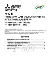
Mitsubishi Electric FR-F800 Instruction Manual (32 pages)
Brand:
Mitsubishi Electric
| Category:
Inverter
| Size: 1.78 MB
Table of Contents
Table of Contents
1
Inverter Installation and Precautions
4
Wiring
6
Failsafe System Which Uses the Inverter
13
Precautions for Use of the Inverter
13
Inverter Function Setting
15
Troubleshooting
21
Specifications
23
Mitsubishi Electric FR-F800 Instruction Manual (16 pages)
Safety Stop Function
Brand:
Mitsubishi Electric
| Category:
Inverter
| Size: 0.42 MB
Table of Contents
Table of Contents
1
General Description
3
Installation and Wiring
5
Example of Safety System Configuration
9
Test and Checking Failure
12
Safety Parameters of Fr-A800/F800
13
Mitsubishi Electric FR-F800 Instruction Manual (15 pages)
Brand:
Mitsubishi Electric
| Category:
Inverter
| Size: 0.33 MB
Table of Contents
Table of Contents
1
General Description
3
Installation and Wiring
5
Example of Safety System Configuration
9
Test and Checking Failure
12
Safety Parameters of Fr-A800/F800
13
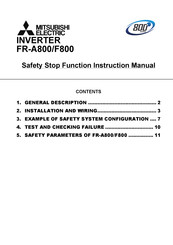
Mitsubishi Electric FR-F800 Safety Stop Function Instruction Manual (14 pages)
Safety Stop Function
Brand:
Mitsubishi Electric
| Category:
Inverter
| Size: 0.29 MB
Table of Contents
Table of Contents
1
General Description
3
Installation and Wiring
4
Operation Panel
6
Example of Safety System Configuration
8
Test and Checking Failure
11
Safety Parameters of Fr-A800/F800
12
Advertisement
Related Products
Mitsubishi Electric FR-F800-E
Mitsubishi Electric FR-F806-E
Mitsubishi Electric FR-F802-E
Mitsubishi Electric FR-F806
Mitsubishi Electric FR-F802
Mitsubishi Electric FR-F860-04420
Mitsubishi Electric FR-F860-00027
Mitsubishi Electric FR-F860-00680-E
Mitsubishi Electric FR-F860-00450-E-N6
Mitsubishi Electric FR-F820-03160
Mitsubishi Electric Categories
Air Conditioner
Controller
Projector
Inverter
Heat Pump
More Mitsubishi Electric Manuals
Login
Sign In
OR
Sign in with Facebook
Sign in with Google
Upload manual
Upload from disk
Upload from URL