Sign In
Upload
Manuals
Brands
Milnor Manuals
Washer
68036M5K
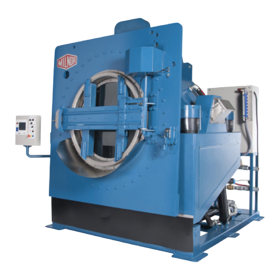
Milnor 68036M5K Manuals
Manuals and User Guides for Milnor 68036M5K. We have
5
Milnor 68036M5K manuals available for free PDF download: Installation And Service, Schematic/Electrical Parts, Safety Manual, Manual
Milnor 68036M5K Installation And Service (185 pages)
Brand:
Milnor
| Category:
Washer
| Size: 14.43 MB
Table of Contents
Table of Contents
3
Limited Standard Warranty
5
How to Get the Necessary Repair Components
6
Trademarks of Pellerin Milnor Corporation
7
Safety
9
Safety-Tilting Washer-Extractors
10
How to Use the Red Safety Support(S) for Maintenance
16
Safety Stands
19
Safety Light Screen Components & Installation
22
Fastener Torque Requirements
28
Guards and Covers
38
Installation
43
48040F_, 48040H_ & 68036H_ Washer Extractor Installation
44
About the Forces Transmitted by Milnor® Washer-Extractors
49
Shipping Brackets
51
Service Connections
53
Drive
57
Drive Chart 68036M5K
58
Drive Chart 72046M5K
59
Motor Mount 48040M7M
61
Motor Mount 72046M5K
62
Bearing Housing Components and Installation: 68036F5N
73
Air Injection Components
80
Disc Brake
94
Air Cylinder Components and Installation
97
Frame and Tilt
99
Frame Pivots and Tilt Stops
100
Suspension: Marshmellow Springs & Shocks
104
Hydraulic Cylinder
114
Door Assemblies
117
48" Door Installation
118
48" Door Hydraulic Components
122
48" Door
127
Door Latch
132
DRYEL Loading
133
DRYELL Loading
136
DRYELL Folding Doors
141
Water and Steam
145
Water
146
Balancing Valves 72046M5K
152
Steam
155
Single Drain Valve
157
Drain Valve Body with Two Valves
159
Bonnet Assembly
162
Chemical
165
Soap Chute
166
Eight Port Peristaltic Supply Manifold
168
Control and Sensing Assemblies
171
Switch Panel Pivot Arm
172
Tilt Limit Switches
174
Excursion Switch
175
Temperature Probe
176
Advertisement
Milnor 68036M5K Manual (75 pages)
Brand:
Milnor
| Category:
Industrial Equipment
| Size: 2.24 MB
Table of Contents
English
8
Table of Contents
8
Preface
10
About this Operator Guide and this Miltouch™ Washer-Extractor
10
Controls
11
Physical Controls
11
Figure 1 Miltouch™ Control Panel with Tilt
11
Main Controls
12
Loading Controls
12
Figure 2 Resume or Cancel the Formula
12
Emergency Stop Switch (Locking Push Button)
13
How to Use the Miltouch™ Controller
14
The Home Display
14
Figure 3 Emergency Stop Switch
14
Figure 4 the Home Display
15
Load Size Best Practice
16
Loading and Unloading Safety
16
Safety and Best Practice When Loading and Unloading
16
Normal Operation
16
Weighing Goods
17
Apply Control Power
17
Figure 5 Air-Unlatch Door
18
Figure 6 Hydraulically-Operated Automatic Door
18
Tilt the Machine Rearward to Load It
18
Open the Door (Hydraulically-Operated Automatic Door)
18
Open the Door (Air Unlatch)
18
Jog and Load the Cylinder
19
Use a Wet-Down to Compact the Goods
19
Close the Door
20
Close the Door and Jog the Cylinder
20
Tilt the Machine to the Neutral (Non-Tilted) Position
21
Start the Wash Formula
21
To Run a Wash Formula Locally
21
To Run a Wash Formula from the Mildata ® Computer
21
Figure 7 Remote Formula Window
22
About the Mildata Product and Production Data
22
Monitor the Wash Formula
23
The Run Display
23
The Names and Timers Area (A)
23
Figure 8 the Three Information Areas of the Run Display
23
The Machine Status Area (B)
24
Figure 9 the Names and the Timers Area
24
Figure 10 the Machine Status Area
24
How to Monitor Automatic Liquid-Chemical Injections
25
Manual Control and Diagnostics Area (C)
25
Respond to the End of the Cycle
25
Open the Door and Tilt the Machine Forward to Unload It
25
Figure 11 Chemicals from Valves 1 and 2 Injecting
25
Figure 12 Standard Controls
25
Jog and Unload the Cylinder
26
Chemical Supplies Intervention
27
Operator Intervention
27
Troubleshooting
27
Error Intervention
28
Formula Intervention
28
Figure 13 Chemical Injection Dialog Box
28
Modify Step Timer
29
Figure 14 Formula Control Areas
29
Figure 15 Pop-Up Controls for Step Timer
29
Figure 17 Pop-Up Controls for Drain Valves
30
Modify Drain Valves
30
Figure 16 Pop-Up Controls for Water Valves
30
Modify Water Valves
30
Modify Steam and Cooldown
31
Modify Cylinder Speed
31
Modify Water Temperature
31
Figure 18 Pop-Up Controls for Steam and Cooldown Valves
31
Figure 19 Pop-Up Controls for Cylinder Speed
31
Figure 20 Pop-Up Controls for Water Temperature
31
Figure 22 Resume or Cancel the Formula
32
To Cancel a Formula
32
Figure 21 Pop-Up Controls for Water Level
32
Modify Water Level
32
Errors
33
Miltouch-EX™ Error Messages
33
Figure 23 Sample Error Code Dialog Box
33
Figure 24 Transducer Tube
34
Figure 25 Schematic of Typical Drain Circuit
34
Error Correction
36
Figure 26 Error Causes/Solutions Display
37
How to Contact Milnor
38
Pellerin Milnor ® Corporation Contact Information
38
Deutsch
42
Informationen zu diesem Bedienerhandbuch und dieser Miltouch
44
Vorwort
44
Waschschleudermaschine
44
Bedienelemente
45
Physische Bedienelemente
45
Bedienelemente zur Beladung
46
Hauptbedienelemente
46
Notstoppschalter (Einrastender Druckschalter)
47
Der Startbildschirm
48
Verwenden der Miltouch™-Steuerung
48
Normalbetrieb
50
Sicherheit Beim Beladen und Entladen
50
Sicherheit und Beste Praxis Beim Beladen und Entladen
50
Beste Praxis für Beladungsmenge
51
Wiegen von Artikeln
51
Einschalten der Stromversorgung der Steuerung
52
Öffnen der Tür (Druckluftentriegelung)
52
Öffnen der Tür (Hydraulisch Betriebene Automatiktür)
52
Manuelles Drehen und Beladen der Trommel
53
Zum Beladen Kippen Sie die Maschine nach Hinten
53
Artikel
54
Schließen Sie die Tür
54
Verwenden eines „Wet-Down" (Wäschebefeuchtung) zur Komprimierung der
54
Kippen Sie die Maschine Zurück in die Neutrale (nicht Gekippte) Position
55
Schließen der Tür und Manuelles Drehen der Trommel
55
Ausführen eines Lokalen Waschprogramms
56
Ausführen eines Waschprogramms über den Mildata Computer
56
Starten Sie das Waschprogramm
56
Informationen zum Produkt Mildata und den
57
Produktionsdaten
57
Der Bildschirm „Run" (Betrieb)
58
Überwachen Sie das Waschprogramm
58
Bereich (A) „Namen und Timer
59
Bereich (B) „Maschinenstatus
59
Bereich „Manuelle Steuerung und Diagnose" (C)
60
Rückmeldung am Ende des Zyklus
60
Öffnen Sie die Tür und Kippen Sie die Maschine nach Vorn, um Sie zu
60
Überwachen der Automatischen Flüssigwaschmittel-Einspülung
60
Manuelles Drehen und Entladen der Trommel
61
Fehlersuche
62
Handlungsbedarf Bezüglich der Waschmittelvorräte
62
Handlungsbedarf Seitens des Bedieners
62
Handlungsbedarf bei Fehlern
63
Programmeingriff
63
Timer Anpassen
64
Ablassventile Anpassen
65
Wasserventile Anpassen
65
Dampf und Abkühlung Anpassen
66
Trommelgeschwindigkeit Anpassen
66
Abbrechen eines Programms
67
Wasserstand Anpassen
67
Wassertemperatur Anpassen
67
Abbildung 23Beispiel für ein Fehlercode-Dialogfenster
68
Abbildung 24Niveaurohr
69
Abbildung 25Schematische Darstellung eines Typischen Ablass-Schaltkreises
69
Abbildung 26Der Bildschirm „Fehlerursachen/-Lösungen
73
Pellerin Milnor Corporation Kontaktinformationen
74
Tabelle
74
Milnor 68036M5K Safety Manual (79 pages)
Tilting Washer-extractor
Brand:
Milnor
| Category:
Washer
| Size: 0.99 MB
Table of Contents
English
8
Table of Contents
8
1 For Owner/Management
10
Vital Safety Information for Owner/Management
10
Preservation of Safe Product Design
10
Safety in Laundry Design
10
Fostering a Safe Laundry Facility
11
Proximity Safeguarding for Automatic Shuttle Conveyors
12
Applicability
12
References for Proximity Safeguarding
13
Hazards to Personnel in Proximity to Shuttle Conveyors
13
How Milnor Accommodates Proximity Safeguarding
14
Examples of Safety Fencing with Interlocked Gates
14
Figure
14
Figure 1 Example Fence Layout for Automated Laundering System Where One
15
Figure 2 Example Fence Layout for Automated Laundering System Where Two
15
Fence Dimensions
16
Fence Materials and Setback
16
Gates
16
Control Circuitry
16
System Emergency Stop Switches
16
Isolating Individual Machine Controls
16
Recommended Signage
17
Wiring Safety Fence Gate Interlocks on Milnor Shuttles, Presses and Centrifugal Extractors
17
Precautions
17
Wiring Guidelines
17
Testing
18
Testing Gate Interlocks
18
Testing Three-Wire Circuit Components on each Interlocked Machine
18
Table 1 Typical Three-Wire Circuit Components
19
2 For All Users
20
Internal Electrical and Mechanical Hazards
20
Safety Placards-Internal Electrical and Mechanical Hazards
20
Safety Alert Messages-Internal Electrical and Mechanical Hazards
20
External Mechanical Hazards
21
Safety Placards-External Mechanical Hazards
21
Figure 4 External Mechanical Hazards
21
Safety Alert Messages-External Mechanical Hazards
22
Cylinder and Processing Hazards
22
Safety Placards-Cylinder and Processing Hazards
22
Safety Alert Messages-Cylinder and Processing Hazards
23
Figure 5 Cylinder and Processing Hazards
23
Safety Alert Messages-Unsafe Conditions
24
Damage and Malfunction Hazards
24
Hazards Resulting from Inoperative Safety Devices
24
Hazards Resulting from Damaged Mechanical Devices
25
Careless Use Hazards
26
Careless Operation Hazards-Vital Information for Operator Personnel (See also Operator Hazards Throughout Manual)
26
Careless Servicing Hazards-Vital Information for Service Personnel (See also Service Hazards Throughout Manuals)
26
Español
32
Contenido
33
1 Para el Propietario/Administrador
34
Información Esencial de Seguridad para el Propietario/Administrador
34
Conservación del Diseño de Productos Seguros
34
Seguridad en el Diseño de la Lavandería
34
Propiciación de unas Instalaciones de Lavandería Seguras
35
Protección de Proximidad para Cintas Transportadoras Automáticas
37
Aplicabilidad
37
Referencias para Protección de Proximidad
37
Peligros para el Personal en Proximidad a Cintas Transportadoras
37
Cómo Incorpora Milnor la Protección de Proximidad
38
Ejemplos de Barreras de Seguridad con Puertas Enclavadas
39
Dimensiones de la Barrera
41
Materiales y Retroceso de la Barrera
41
Puertas
41
Circuitos de Control
41
Interruptores de Parada de Emergencia del Sistema
41
Aislamiento de Controles de Máquina Individuales
42
Señalización Recomendada
42
Enclavamiento de la Puerta de la Barrera de Seguridad para el Cableado en Cintas
42
Precauciones
42
Pautas de Cableado
43
Prueba
43
Prueba de Enclavamientos de Puerta
44
Prueba de Componentes del Circuito Trifásico en cada Máquina con Enclavamiento
44
2 Para todos Los Usuarios
45
Riesgos Electromecánicos Internos
45
Placas de Seguridad: Riesgos Electromecánicos Internos
45
Mensajes de Alerta de Seguridad: Riesgos Electromecánicos Internos
45
Riesgos Mecánicos Externos
46
Placas de Seguridad: Riesgos Mecánicos Externos
46
Mensajes de Alerta de Seguridad: Riesgos Mecánicos Externos
47
Riesgos del Tambor y el Procesamiento
48
Placas de Seguridad: Riesgos del Tambor y el Procesamiento
48
Mensajes de Alerta de Seguridad: Riesgos del Tambor y el Procesamiento
48
Mensajes de Alerta de Seguridad: Condiciones no Seguras
50
Riesgos por el Deterioro y el Funcionamiento Incorrecto
50
Riesgos Causados por Dispositivos de Seguridad Inoperantes
50
Riesgos Causados por Dispositivos Mecánicos Deteriorados
51
Riesgos de Los Descuidos en el Uso
52
Riesgos de Los Descuidos en el Manejo: Información Vital para Los Operadores (Consulte También Los Riesgos para el Operador en todo el Manual)
52
Riesgos de Los Descuidos en el Mantenimiento y las Reparaciones: in
53
Deutsch
58
1 Für Eigentümer und Management
60
Wichtige Sicherheitsinformationen für den Eigentümer/Das Management
60
Wahrung eines Sicheren Produktdesigns
60
Sicherheitskonzept für Wäschereien
60
Schaffung eines Sicheren Wäschereibetriebs
61
Annäherungsschutz für Automatische Transportbänder
63
Anwendbarkeit
63
Referenzen zu Annäherungsschutz
63
Gefahren für Mitarbeiter in der Nähe von Transportsystem-Förderbändern
63
So Sieht Milnor den Annäherungsschutz vor
64
Beispiel für Umzäunungen mit Elektrisch Überwachten Türen
65
Maße der Umzäunung
67
Material und Abstand der Umzäunung
67
Türen
67
Steuerungsschaltung
67
System-Notstoppschalter
67
Abtrennen Einzelner Maschinensteuerungen
68
Empfohlene Beschilderung
68
Verdrahtung von Sicherheitstürschaltern an Transportsystemen, Pressen und Ent
68
Warnhinweise
68
Richtlinien zur Verdrahtung
69
Prüfen
69
Prüfen der Türschalter
70
Prüfen der Dreileiterschaltungskomponenten der Einzelnen Gesicherten Maschinen
70
2 Für alle Benutzer
71
Interne Elektrische und Mechanische Gefahren
71
Sicherheitsschilder - Interne Elektrische und Mechanische Gefahren
71
Sicherheitswarnmeldungen - Interne Elektrische und Mechanische Gefahren
71
Externe Mechanische Gefahren
72
Sicherheitsschilder - Externe Mechanische Gefahren
72
Sicherheitswarnmeldungen - Externe Mechanische Gefahren
73
Gefahren Bezüglich Trommel und Verarbeitung
74
Sicherheitsschilder - Gefahren Bezüglich Trommel und Verarbeitung
74
Sicherheitswarnmeldungen - Gefahren Bezüglich Trommel und Verarbeitung
74
Sicherheitswarnmeldungen - Unsichere Bedingungen
76
Gefahren durch Schäden und Störungen
76
Gefahren Aufgrund von Defekten Sicherheitsvorrichtungen
76
Gefahren Aufgrund von Beschädigten Mechanischen Vorrichtungen
77
Gefahren durch Nachlässige Behandlung
78
Advertisement
Milnor 68036M5K Manual (49 pages)
Brand:
Milnor
| Category:
Industrial Equipment
| Size: 5.79 MB
Table of Contents
Table of Contents
8
Machine Description and Identification
11
About this Manual and Your Milnor® Machine
11
Description
11
Machine Identification
11
Machine Data Plate
11
Figure 1 Machine Data Plate
11
Safety
12
Tilting Washer Extractors
12
Safety Alert Messages-Internal Electrical and Mechanical Hazards
12
Safety Alert Messages-Cylinder and Processing Hazards
13
Safety Alert Messages-Unsafe Conditions
14
Damage and Malfunction Hazards
14
Hazards Resulting from Inoperative Safety Devices
14
Hazards Resulting from Damaged Mechanical Devices
15
Careless Use Hazards
15
Careless Operation Hazards-Vital Information for Operator Personnel (See also Operator Hazards Throughout Manual)
15
Careless Servicing Hazards-Vital Information for Service Personnel (See also Service Hazards Throughout Manuals)
16
Use the Red Safety Supports for Maintenance - 48040M7K, 68036M5K
17
What Safety Supports Are Provided and Why
17
How to Deploy the Safety Stands - 68036M5K, 72044M5K
18
How to Deploy the Safety Stands - 48040M7K
19
How to Deploy the Load Chute Safety Bar
19
Prevent Damage from Chemical Supplies and Chemical Systems
20
How Chemical Supplies Can Cause Damage
20
Dangerous Chemical Supplies and Wash Formulas
20
Incorrect Configuration or Connection of Equipment
20
Figure 2 Incorrect Configurations that Let the Chemical Supply Go in the Ma
21
Equipment and Procedures that Can Prevent Damage
22
Use the Chemical Manifold Supplied
22
Figure 3 Incorrect Configurations that Let the Chemical Supply Go in the Ma
22
Figure 4 Examples of Manifolds for Chemical Tubes. Your Equipment Can Look
22
Close the Line
23
Do Not Let a Vacuum Occur
23
Flush the Chemical Tube with Water
23
Put the Chemical Tube Fully below the Inlet
23
Prevent Leaks
23
Figure 5 a Configuration that Prevents Flow in the Machine When the Pump Is off (if the Chemical Tube and Tank Have no Pressure)
23
Routine Maintenance
24
Maintenance Summary
24
Guards and Related Components
25
Filters, Screens, and Sensitive Components
25
Table 1 Guards and Related Components
25
Table 2 Filters, Screens, and Sensitive Components
25
Fluid Containers
26
Components that Become Worn
26
Table 3 Fluid Containers
26
Bearings and Bushings
27
Motor Grease Schedule
27
Table 4 Components that Become Worn
27
Table 5 Bearings and Bushings
27
Mechanisms and Settings
28
How to Remove Contamination
28
Table 6 Motor Grease Schedule
28
Table 7 Mechanisms and Settings
28
Table 8 Contamination Types, Cleaning Agents, and Procedures
28
Lubricant Identification
29
Grease Gun Procedures
30
Table 9 Lubricant Identification
30
Procedures for Bearing Components Connected to a Grease Plate
31
Procedures for Motors
31
Figure 6 Motor Grease Maintenance Conditions
32
How to Show the Maintenance on a Calendar
33
Table 10 Motor Grease Intervals and Quantities
33
Maintenance Components-Machines and Controls Group
34
How to Examine V-Belts and Pulleys
34
Figure 7 Belt and Pulley Conditions to Look for
34
Table 11 Where to Put Marks on a Calendar
34
Figure 8 How to Adjust Belt Tension on a Machine that Uses Spring Tension
35
Inverters
36
Chemical Devices
36
Figure 9 Electric Box and Inverter. These Are Examples. Your Machine Can Look
36
Water and Steam Devices
37
Figure 10 Chemical Inlet Manifolds for Chemical Pump Systems. See Caution
37
Figure 11 Soap Chute and Optional 5-Compartment Supply Injector. These Are Ex
37
Figure 12 Air Tube for the Water Level Sensor. These Are Examples. Your Ma- Chine Can Look Different
38
Figure 13 Water Pressure Regulator for Chemical Flush. These Are Examples
38
How to Examine Compressed Air Mechanisms
39
Compressed Air Inlet Strainers. These Are Examples. Your Machine Can Look Different
39
Compressed Air Mechanisms These Are Examples. Your Machine Can Look Different
41
Photoeyes and Proximity Switches
42
How to Do a Test of Emergency Stop Mechanisms
42
Speed Sensor (Photoeye) on some Machines
42
Proximity Switches These Are Examples. Your Machine Can Look Different
42
Maintenance Components-Large Extractors
44
Lubricant Maintenance for Grease-Filled Drive Bearings
44
Lubricant Maintenance for Non-Drive Components
44
Grease Ports for Grease-Only Bearing Assembly
44
Grease Ports for Door-Open Pocket Models. These Are Examples
44
How to Do a Test of the Mechanical Brake
45
About the Shock Absorbers
47
Maintenance Components-Hydraulic Power Group
48
How to Replace the Hydraulic Oil or Add Oil to the Full Mark
48
Hydraulic Power Components and System Oil Capacity
48
How to Make Sure that the Hydraulic Oil Is Serviceable
49
How to Examine the Hydraulic System for Leaks
49
Milnor 68036M5K Schematic/Electrical Parts (83 pages)
MilTouch-EX Controls
Brand:
Milnor
| Category:
Control Unit
| Size: 3.04 MB
Advertisement
Related Products
Milnor 68036F5B
Milnor 68036F5N
Milnor 68036 Series
Milnor 60044 SG3
Milnor 64040E6N
Milnor 64046E6N
Milnor 60044WP2
Milnor 60044SP2
Milnor 60044WR3
Milnor 60044WR2
Milnor Categories
Washer
Industrial Equipment
Controller
Laundry Appliance
Dryer
More Milnor Manuals
Login
Sign In
OR
Sign in with Facebook
Sign in with Google
Upload manual
Upload from disk
Upload from URL