Sign In
Upload
Manuals
Brands
Milnor Manuals
Washer
36021
Milnor 36021 Manuals
Manuals and User Guides for Milnor 36021. We have
5
Milnor 36021 manuals available for free PDF download: Mechanical Parts And Service, Service Manual, Manual, Maintenance Manual, Operator's Manual
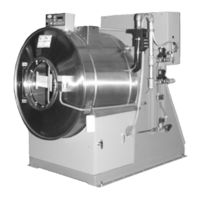
Milnor 36021 Mechanical Parts And Service (116 pages)
Brand:
Milnor
| Category:
Laundry Appliance
| Size: 8.61 MB
Table of Contents
Table of Contents
3
36021V5J, V5Z, V7Z; 36026V5J, V5Z, V7Z; 42026V5J, V6Z
6
General Service & Safety-Related Components
7
Limited Standard Warranty
8
How to Get the Necessary Repair Components
9
Trademarks
9
Safety - Rigid Washer Extractors
10
Safety Alert Messages-Internal Electrical and Mechanical Hazards
10
Safety Alert Messages-Cylinder and Processing Hazards
10
Table 1 Trademarks
10
Safety Alert Messages-Unsafe Conditions
12
Damage and Malfunction Hazards
12
Hazards Resulting from Inoperative Safety Devices
12
Hazards Resulting from Damaged Mechanical Devices
12
Careless Use Hazards
13
Careless Operation Hazards-Vital Information for Operator Personnel (See also Operator Hazards Throughout Manual)
13
Careless Servicing Hazards-Vital Information for Service Personnel (See also Service Hazards Throughout Manuals)
13
Safety Placard Use and Placement 36021CPE, NSP, V5J, V5Z and 36026V5J, V5Z
16
36021CPE, NSP, V5J, V5Z and 36026V5J, V5Z
18
36021V7J, V7Z; 36026V7J/W, V7Z; 42026V5J; 42026V6J/W, V7Z; 42030V6J, V6Z
20
Safety Placard Use and Placement-ISO
22
36021V7J, V7Z; 36026V7J/W, V7Z; 42026V5J; 42026V6J/W, V6Z; 42030V6J, V6Z
22
Guards & Covers 36021V5Z, 36026V5Z
24
Guards & Covers 36021V7Z, 36026V7Z, 42026V5J, 42026V6Z, 42030V6Z
26
Figure 1 Front Covers
26
Figure 2 Rear Covers and Side Gasket
27
Torque Requirements for Fasteners
28
Torque Values
28
Fasteners Made of Carbon Steel
28
Without a Threadlocker
28
Figure
28
Table 8 Torque Values for Standard Fasteners with Maximum 5/16-Inch Diameters and no Lubricant
28
Table 9 Torque Values for Standard Fasteners Larger than 5/16-Inch Diameters and no Lubricant
29
Table 10 Torque Values for Plated Fasteners with Maximum 5/16-Inch Diameters and no Lubricant
29
With a Threadlocker
30
Table 11 Torque Values for Plated Fasteners Larger than 5/16-Inch Diameters and no Lubricant
30
Stainless Steel Fasteners
32
Preparation
33
How to Apply a Threadlocker
34
Blind Holes
34
Through Holes
34
Figure 4 Apply Threadlocker in a Blind Hole
34
Figure 5 Apply Threadlocker in a through Hole
35
Drive Assemblies
36
Drive Chart 36021V5J, 36021V5Z, 36026V5J, 36021V5Z
38
Drive Chart 36021V7J, 36021V7Z, 36026V7J, 36026V7Z
40
Drive Chart 42026V5J, 42026V6J, 42026V6Z, 42030V6J, 42030V6Z
42
Drive Pulley and Belt Maintenance
44
Pulley Requirements
44
Condition of Grooves on Pulleys
44
Pulley and Shaft Position
45
Keep Run-Out in Tolerance
46
Belt Requirements
47
Condition of Belts
47
Tension of Belts
48
The Pulleys Must Stay Aligned When You Adjust the Belt Tension
49
How to Do Maintenance on Pulleys and Belts
50
Typical Steps to Replace Pulleys and Belts
50
Run-Out
50
Examples of Procedures Used at the Milnor Factory to Align
51
Pulleys
51
Motor Mount 30015, 30022, 36021, 36026, 42026, & 42030Vxx,Txx
53
Bearing Assembly 36021V5J, 36021V5Z, 36026V5J, 36026V5Z with Starplate
56
Bearing Assembly 36021V7Z, 36026V7Z, 42026V5J, 42026V6Z, 42030V6Z
59
Cylinder & Shell
63
Main Bearing, Shell, Cylinder Installation
64
36021V5J, 36021V5Z, 36026V5J, 36026V5Z with Starplate
64
36021V7Z, 36026V7Z, 42026V5J, 42026V6Z, 42030V6Z
69
Cross Section of Shell, Cylinder, Bearing, and Frame
69
Main Bearing, Shell, and Cylinder Installation
70
20 Inch Door Assemblies after 8/2016
73
42030V6Z
74
Mcr12; Mct16/18/27; Mwf18/27; Mwr27/36; Mwt12/16/18/27; 3015/3022T6X, Vrj, V8Z, Vzz; 3022X8R; 36021V5J, V5Z, V7Z; 36026V5J, V5Z, V7Z
78
42026V5J, V6Z. 42030V6Z
78
Door Lock Mechanisms
79
Door Handle and Lock Actuator
81
Door Handle and Lock Actuator
82
Chemical Supply Devices
84
42030V6Z
88
Soap Chute 36021V5J, V5Z, V7Z; 36026V5J, V5Z, V7Z; 42026V5J, V6Z; 42030V6Z
88
42030V6Z
90
Supply Chute
90
Valve Manifold
91
Water & Steam
94
Water Schematic 36021V5J, V5Z, V7Z; 36026V5J, V5Z, V7Z; 42026V5J, V6Z; 42030V6Z
96
42030V6Z
98
Steam Inlet 36021V5J, V5Z, V7Z; 36026V5J, V5Z, V7Z; 42026V5J, V6Z; 42030V6Z
104
Drain Valve 36021V5J, V5Z, V7Z; 36026V5J, V5Z, V7Z; 42026V5J, V6Z; 42030V6Z
106
Inch Electrical Drain Valve
108
Control & Sensing
110
42030V6Z
111
36021V5J, V5Z, V7Z; 36026V5J, V5Z, V7Z; 42026V5J, V6Z; 42030V6Z
112
Vibration Safety Switch Adjustments
114
What the Vibration Safety Switch Does
114
Adjustments
114
Vibration Safety Switch
116
Advertisement
Milnor 36021 Service Manual (108 pages)
Washer-Extractors
Brand:
Milnor
| Category:
Washer
| Size: 9.72 MB
Table of Contents
Table of Contents
3
Page Description
4
How to Order Parts
7
Safety-Rigid Washer Extractors
8
About the Forces Transmitted by Milnor Washer-Extractors
18
Avoiding Damage from Allied Remote Chemical Delivery Systems
25
Section 1: Service and Maintenance
39
Preventive Maintenance
40
Fastener Torque Requirements
48
Section 2: Drive Assemblies
61
Motor Mount
66
Section 3: Bearing Assemblies
67
Section 4: Shell and Door Assemblies
77
Section 5: Control and Sensing
85
Milnor 36021 Manual (38 pages)
Brand:
Milnor
| Category:
Laundry Appliance
| Size: 3.48 MB
Table of Contents
Table of Contents
8
Machine Description and Identification
11
About this Manual and Your Milnor® Machine
11
Description
11
Machine Identification
11
Machine Data Plate
11
Figure 1 Machine Data Plate
11
Safety
12
Safety - Rigid Washer Extractors
12
Safety Alert Messages-Internal Electrical and Mechanical Hazards
12
Safety Alert Messages-Cylinder and Processing Hazards
12
Safety Alert Messages-Unsafe Conditions
14
Damage and Malfunction Hazards
14
Hazards Resulting from Inoperative Safety Devices
14
Hazards Resulting from Damaged Mechanical Devices
14
Careless Use Hazards
15
Careless Operation Hazards-Vital Information for Operator Personnel (See also Operator Hazards Throughout Manual)
15
Careless Servicing Hazards-Vital Information for Service Personnel (See also Service Hazards Throughout Manuals)
15
Prevent Damage from Chemical Supplies and Chemical Systems
16
How Chemical Supplies Can Cause Damage
16
Dangerous Chemical Supplies and Wash Formulas
16
Incorrect Configuration or Connection of Equipment
16
Figure 2 Incorrect Configurations that Let the Chemical Supply Go in the Ma
17
Equipment and Procedures that Can Prevent Damage
18
Use the Chemical Manifold Supplied
18
Figure 3 Incorrect Configurations that Let the Chemical Supply Go in the Ma
18
Figure 4 Examples of Manifolds for Chemical Tubes. Your Equipment Can Look
18
Close the Line
19
Do Not Let a Vacuum Occur
19
Flush the Chemical Tube with Water
19
Put the Chemical Tube Fully below the Inlet
19
Prevent Leaks
19
Figure 5 a Configuration that Prevents Flow in the Machine When the Pump Is off (if the Chemical Tube and Tank Have no Pressure)
19
Routine Maintenance
20
Maintenance Summary
20
Guards and Related Components
21
Filters, Screens, and Sensitive Components
21
Table 1 Guards and Related Components
21
Table 2 Filters, Screens, and Sensitive Components
21
Fluid Containers
22
Components that Become Worn
22
Bearings and Bushings
22
Motor Grease Schedule
22
Table 3 Fluid Containers
22
Mechanisms and Settings
23
How to Remove Contamination
23
Lubricant Identification
24
Grease Gun Procedures
25
Procedures for Motors
25
Figure 6 Motor Grease Maintenance Conditions
26
How to Show the Maintenance on a Calendar
27
Maintenance Components-Machines and Controls Group
29
How to Examine V-Belts and Pulleys
29
Figure 7 Belt and Pulley Conditions to Look for
29
Inverters
30
Figure 8 How to Adjust Belt Tension on a Machine that Uses Spring Tension
30
Chemical Devices
31
Figure 9 Electric Box and Inverter. These Are Examples. Your Machine Can Look
31
Water and Steam Devices
32
Figure 10 Chemical Inlet Manifolds for Chemical Pump Systems. See Caution
32
Figure 11 Soap Chute and Optional 5-Compartment Supply Injector. These Are Ex
32
Figure 12 Air Tube for the Water Level Sensor. These Are Examples. Your Ma- Chine Can Look Different
33
Figure 13 Water Pressure Regulator for Chemical Flush. These Are Examples
33
Your Machine Can Look Different
33
How to Examine Compressed Air Mechanisms
34
Figure 14 Steam Inlet Strainer. These Are Examples. Your Machine Can Look Different
34
Figure 15 Compressed Air Inlet Strainers. These Are Examples. Your Machine Can Look Different
34
Figure 16. Self-Purging Air Line Filter to Remove Moisture and Other Contamination. These Are Examples. Your Machine Can Look Different
35
How to Do a Test of Emergency Stop Mechanisms
36
Figure 17 Compressed Air Mechanisms These Are Examples. Your Machine Can Look Different
36
Maintenance Components-Large Extractors
38
Lubricant Maintenance for Oil-Filled Bearing Housings
38
Figure 18 Oil Maintenance Areas for Bearing Assembly. a 30022T5E Is Shown
38
Your Machine Can Look Different
38
Advertisement
Milnor 36021 Maintenance Manual (38 pages)
Washer-extractor, Rigid Console, Grease Bearings, _V6Z, _V7Z
Brand:
Milnor
| Category:
Washer
| Size: 3.44 MB
Table of Contents
Table of Contents
8
Machine Description and Identification
11
About this Manual and Your Milnor® Machine
11
Description
11
Machine Identification
11
Machine Data Plate
11
Figure 1 Machine Data Plate
11
Safety
12
Safety - Rigid Washer Extractors
12
Safety Alert Messages-Internal Electrical and Mechanical Hazards
12
Safety Alert Messages-Cylinder and Processing Hazards
12
Safety Alert Messages-Unsafe Conditions
14
Damage and Malfunction Hazards
14
Hazards Resulting from Inoperative Safety Devices
14
Hazards Resulting from Damaged Mechanical Devices
14
Careless Use Hazards
15
Careless Operation Hazards-Vital Information for Operator Personnel (See also Operator Hazards Throughout Manual)
15
Careless Servicing Hazards-Vital Information for Service Personnel (See also Service Hazards Throughout Manuals)
15
Prevent Damage from Chemical Supplies and Chemical Systems
16
How Chemical Supplies Can Cause Damage
16
Dangerous Chemical Supplies and Wash Formulas
16
Incorrect Configuration or Connection of Equipment
16
Figure 2 Incorrect Configurations that Let the Chemical Supply Go in the Ma
17
Equipment and Procedures that Can Prevent Damage
18
Use the Chemical Manifold Supplied
18
Figure 3 Incorrect Configurations that Let the Chemical Supply Go in the Ma
18
Figure 4 Examples of Manifolds for Chemical Tubes. Your Equipment Can Look
18
Close the Line
19
Do Not Let a Vacuum Occur
19
Flush the Chemical Tube with Water
19
Put the Chemical Tube Fully below the Inlet
19
Prevent Leaks
19
Figure 5 a Configuration that Prevents Flow in the Machine When the Pump Is off (if the Chemical Tube and Tank Have no Pressure)
19
Routine Maintenance
20
Maintenance Summary
20
Guards and Related Components
21
Filters, Screens, and Sensitive Components
21
Table 1 Guards and Related Components
21
Table 2 Filters, Screens, and Sensitive Components
21
Components that Become Worn
22
Bearings and Bushings
22
Motor Grease Schedule
22
Mechanisms and Settings
22
Table 3 Components that Become Worn
22
Table 4 Bearings and Bushings
22
How to Remove Contamination
23
Lubricant Identification
24
Grease Gun Procedures
25
Procedures for Bearing Components Connected to a Grease Plate
25
Procedures for Motors
26
Figure 6 Motor Grease Maintenance Conditions
27
How to Show the Maintenance on a Calendar
28
Maintenance Components-Machines and Controls Group
29
How to Examine V-Belts and Pulleys
29
Figure 7 Belt and Pulley Conditions to Look for
29
Figure 8 How to Adjust Belt Tension on a Machine that Uses Spring Tension
30
Inverters
31
Chemical Devices
31
Figure 9 Electric Box and Inverter. These Are Examples. Your Machine Can Look
31
Water and Steam Devices
32
Figure 10 Chemical Inlet Manifolds for Chemical Pump Systems. See Caution
32
Figure 11 Soap Chute and Optional 5-Compartment Supply Injector. These Are Ex
32
Figure 12 Air Tube for the Water Level Sensor. These Are Examples. Your Ma- Chine Can Look Different
33
Figure 13 Water Pressure Regulator for Chemical Flush. These Are Examples
33
How to Examine Compressed Air Mechanisms
34
Figure 14 Steam Inlet Strainer. These Are Examples. Your Machine Can Look Different
34
Figure 15 Compressed Air Inlet Strainers. These Are Examples. Your Machine Can Look Different
34
Figure 16. Self-Purging Air Line Filter to Remove Moisture and Other Contamination. These Are Examples. Your Machine Can Look Different
35
How to Do a Test of Emergency Stop Mechanisms
36
Figure 17 Compressed Air Mechanisms These Are Examples. Your Machine Can Look Different
36
Maintenance Components-Large Extractors
38
Lubricant Maintenance for Grease-Filled Drive Bearings
38
Figure 18 Grease Ports for Grease-Only Bearing Assembly
38
Milnor 36021 Operator's Manual (34 pages)
Brand:
Milnor
| Category:
Washer
| Size: 1.12 MB
Table of Contents
Table of Contents
8
1 Preface
10
About this Operator Guide and this Miltouch™ Washer-Extractor
10
2 Controls
11
Physical Controls
11
Figure 1 Control Panel
11
Figure 2 Control Panel
11
Emergency Stop Switch (Locking Push Button)
12
Figure 3 Emergency Stop Switch
12
How to Use the Miltouch™ Controller
13
The Home Display
13
Figure 4 the Home Display
14
3 Normal Operation
15
Safety and Best Practice When Loading and Unloading
15
Loading and Unloading Safety
15
Load Size Best Practice
15
Weighing Goods
16
Apply Control Power
16
Open the Door (Turn-Knob)
17
Open the Door (Push-Plate)
17
Load the Cylinder
17
Close the Door
17
Figure 5 Door with a Turn-Knob
17
Figure 6 Door with a Push-Plate
17
Start the Wash Formula
18
To Run a Wash Formula Locally
18
To Run a Wash Formula from the Mildata Computer
18
Figure 7 Remote Formula Window
18
About the Mildata ® Product and Production Data
19
Monitor the Wash Formula
20
The Run Display
20
The Names and Timers Area (A)
20
Figure 8 the Three Information Areas of the Run Display
20
Figure 9 the Names and the Timers Area
20
The Machine Status Area (B)
21
How to Monitor Automatic Liquid-Chemical Injections
21
Manual Control and Diagnostics Area (C)
21
Figure 10 the Machine Status Area
21
Figure 11 Chemicals from Valves 1 and 2 Injecting
21
Respond to the End of the Cycle
22
Open the Door and Unload the Cylinder
22
Figure 12 Standard Controls
22
4 Troubleshooting
23
Operator Intervention
23
Chemical Supplies Intervention
23
Error Intervention
24
Formula Intervention
24
Figure 13 Chemical Injection Dialog Box
24
Figure 14 Formula Control Areas
25
Figure 15 Pop-Up Controls for Step Timer
25
Modify Step Timer
25
Figure 16 Pop-Up Controls for Water Valves
26
Figure 17 Pop-Up Controls for Drain Valves
26
Modify Drain Valves
26
Modify Water Valves
26
Figure 18 Pop-Up Controls for Steam and Cooldown Valves
27
Figure 19 Pop-Up Controls for Cylinder Speed
27
Figure 20 Pop-Up Controls for Water Temperature
27
Modify Cylinder Speed
27
Modify Steam and Cooldown
27
Modify Water Temperature
27
Modify Water Level
28
To Cancel a Formula
28
Figure 21 Pop-Up Controls for Water Level
28
Figure 22 Resume or Cancel the Formula
28
Errors
29
Miltouch™ Error Messages
29
Figure 23 Sample Error Code Dialog Box
29
Figure 24 Transducer Tube
30
Figure 25 Schematic of Typical Drain Circuit
30
Error Correction
32
Figure 26 Error Causes/Solutions Display
33
How to Contact Milnor
34
Pellerin Milnor ® Corporation Contact Information
34
Advertisement
Related Products
Milnor 36021C4E
Milnor 36021V5Z
Milnor 36021V7Z
Milnor 36021V7J
Milnor 36021V Series
Milnor 36021V5J
Milnor 36026V7J
Milnor 36026X8J
Milnor 36026X8R
Milnor 36026V7W
Milnor Categories
Washer
Industrial Equipment
Controller
Laundry Appliance
Dryer
More Milnor Manuals
Login
Sign In
OR
Sign in with Facebook
Sign in with Google
Upload manual
Upload from disk
Upload from URL