Sign In
Upload
Manuals
Brands
Liebert Manuals
Controller
AC4
Liebert AC4 Manuals
Manuals and User Guides for Liebert AC4. We have
3
Liebert AC4 manuals available for free PDF download: User Manual, Specification & Installation Sheet
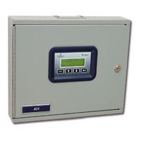
Liebert AC4 User Manual (88 pages)
MONITORING
Brand:
Liebert
| Category:
Control Unit
| Size: 2.94 MB
Table of Contents
Table of Contents
3
1 Introduction
7
Methods of Viewing and Configuring the AC4
7
Data Logs
7
Available Alarms
7
Outside Enclosure Overview
8
Figure 1 AC4 Enclosure-External Features
8
Figure 2 AC4 Enclosure-Internal Features
8
Typical Configuration
9
Figure 3 Typical Configuration
9
Controller Board Overview
10
Table 1 Controller Board Components
10
LED Indicators
12
Table 2 LED Indicators Summary
12
Typical Sequence
13
Figure 4 Example of Typical Sequence
13
2 Installation
14
Installation Considerations
14
Unpacking and Preliminary Inspection
14
Table 3 Packing Manifest
14
Surface-Mounting the AC4
15
Mounting the Panel
15
Figure 5 Mounting Dimensions
15
Flush-Mounting the AC4
16
Mounting the Panel
16
Connect Power to the AC4
17
Figure 6 Electrical Connections to Panel
17
3 Wiring and Connections
18
Wiring Specifications
18
Table 4 Wiring Specifications
18
Connecting Digital Inputs and Outputs
19
Connecting Digital Inputs
19
Connecting Digital Outputs
19
Setting the Digital Output Jumpers
20
Connecting Common Alarm Outputs
20
RS232 Connector
20
Table 5 Digital Output Jumper Settings
20
4 Overview of Menus
21
Table 6 Guide to AC4 Functions
21
Opening Screen Overview
22
Main Menu Overview
22
LCD Menu Overview
22
Figure 7 LCD Menu Overview
22
Table 7 Primary Functions Overview
22
5 View Status Options
23
Figure 8 Menu Overview - View Status Menu
23
View Active Alarms
24
Active Alarms
24
View Alarm Log
25
Alarm Log
25
Backing up the Alarm Log (Service Terminal Interface Only)
25
Table 8 Alarm Log Conditions
25
View Event Log
26
Event Log
26
Backing up the Event Log (Service Terminal Interface Only)
26
Table 9 Event Log Conditions
26
View Input Status
27
Input Status
27
Table 10 Digital Input States
27
View Output Status
28
Output Status
28
Table 11 Digital Output States
28
6 Silence Alarm & Backup Log Files (Service Terminal Interface )
29
Silence Alarm (Service Terminal Interface)
29
Back up Log Files (Service Terminal Interface Only)
30
7 System and Control Options
32
Login
32
Table 12 Valid Characters for Data Entry
32
Figure 9 Menu Overview - System and Control Menu
33
Setup System - Overview
34
Setup System - Setup Inputs
34
Table 13 Default Settings - Digital Inputs
34
Change Label (Name of Input)
35
Define Input as Alarmable or Event
35
Define Input as Normally Open or Normally Closed
35
Table 13 Table
35
Table 14 Input and Output Labels
35
Set up Alarmable Inputs in Latched or Unlatched Mode
36
Set up Delay Time
36
Setup System - Setup Common Alarm
37
Setup System - Setup Zones
38
Set up a Zone
38
Table 15 Default Zones
38
Table 16 Possible Combinations - Outputs Per Zone
38
Setup System - Setup Outputs
39
Define Output as Normally Open or Normally Closed
39
Table 17 Table
39
Table 17 Default Settings - Digital Outputs
39
Define Operating or Standby Mode
40
Enable or Disable an Output Device in Alarm Status
40
Configure Output for Loss of Power ("Fail-Safe")
40
Setup System - Setup System Info
41
Change Password
41
Set Date & Time/Automatic Daylight Saving Time
42
Setup Site ID
42
Backup and Upload Configuration File (Service Terminal Interface Only)
43
Factory Defaults
46
Perform Firmware Update (Service Terminal Interface Only)
46
Setup Operation
48
Table 18 Default Settings - Operation Features
48
Table 19 Table
48
Turn Automatic Sequencing on or off
49
Specify Failed Standby Response
50
Turn Standby Testing on or off
50
Specify Hold Delay Time
51
Specify Restart Time
51
Override Output
52
Table 20 Automatic / Manual Control - Output Points
52
Clear Alarms & Logs
53
Clear Active Alarms
53
Clear the Alarm Log
53
Clear the Event Log
53
8 Specifications
54
AC4 Specifications
54
Comparison of Functions: LCD and Service Terminal Interface
55
Table 21 Guide to AC4 Functions
55
Connecting to the Service Terminal Interface
56
Create a Connection
57
A.2.1 Create a Connection
57
Connect to the Service Terminal Interface
59
Overview of Menus
60
View Status Overview
60
Silence Alarm and Backup Log Files
60
Setup Menu Overview
60
View Status Menus
61
View Active Alarms
62
View Alarm Log
63
View Event Log
64
View Input Status
65
View Output Status
66
Silence Alarm & Back up Log Files (Service Terminal Interface Only)
67
Silence Alarm (Service Terminal Interface Only)
67
Back up Log Files (Service Terminal Interface Only)
68
Setup Menu
69
Setup Inputs
71
A.6.1 Setup Inputs
71
Setup Common Alarm
72
Setup Zones
73
A.6.3 Setup Zones
73
Setup Outputs
74
A.6.4 Setup Outputs
74
Setup System Info
75
Setup Operation
80
A.6.6 Setup Operation
80
Override Output
84
A.6.7 Override Output
84
Clear Alarms & Logs
85
Advertisement
Liebert AC4 User Manual (100 pages)
Brand:
Liebert
| Category:
Controller
| Size: 3.73 MB
Table of Contents
Table of Contents
3
Introduction
7
Methods of Viewing and Configuring the Liebert AC4
7
Data Logs
7
Available Alarms
7
Outside Enclosure Overview
8
Typical Configuration
9
Controller Board Overview
9
LED Indicators
11
Typical Sequence
13
Installation
15
Installation Considerations
15
Unpacking and Preliminary Inspection
15
Surface-Mounting the Liebert AC4
16
Mounting the Panel
16
Flush-Mounting the Liebert AC4
17
Mounting the Panel
18
Connect Power to the Liebert AC4
18
Wiring and Connections
21
Wiring Specifications
21
Connecting Digital Inputs and Outputs
22
Connecting Digital Inputs
22
Connecting Digital Outputs
23
Setting the Digital Output Jumpers
23
Connecting Common Alarm Outputs
24
RS232 Connector
24
Overview of Menus
25
Opening Screen Overview
26
Main Menu Overview
26
LCD Menu Overview
27
View Status Options
29
View Active Alarms
31
Active Alarms
31
View Alarm Log
32
Alarm Log
32
Backing up the Alarm Log (Service Terminal Interface Only)
33
View Event Log
33
Event Log
33
Backing up the Event Log (Service Terminal Interface Only)
34
View Input Status
35
Input Status
35
View Output Status
36
Output Status
36
Silence Alarm & Backup Log Files (Service Terminal Interface)
37
Silence Alarm (Service Terminal Interface)
37
Back up Log Files (Service Terminal Interface Only)
37
System and Control Options
41
Login
41
Setup System - Overview
44
Setup System - Setup Inputs
44
Change Label (Name of Input)
45
Define Input as Normally Open or Normally Closed
46
Define Input as Alarmable or Event
46
Set up Alarmable Inputs in Latched or Unlatched Mode
47
Set up Delay Time
47
Setup System - Setup Common Alarm
48
Setup System - Setup Zones
48
Set up a Zone
49
Setup System - Setup Outputs
50
Define Output as Normally Open or Normally Closed
51
Define Operating or Standby Mode
51
Enable or Disable an Output Device in Alarm Status
51
Configure Output for Loss of Power ("Fail-Safe")
52
Setup System - Setup System Info
52
Change Password
53
Set Date & Time/Automatic Daylight Saving Time
53
Setup Site ID
54
Backup and Upload Configuration File (Service Terminal Interface Only)
54
Factory Defaults
57
Perform Firmware Update (Service Terminal Interface Only)
57
Setup Operation
60
Turn Automatic Sequencing on or off
60
Turn Standby Testing on or off
61
Specify Failed Standby Response
63
Specify Hold Delay Time
63
Specify Restart Time
64
Override Output
64
Clear Alarms & Logs
66
Clear Active Alarms
66
Clear the Alarm Log
66
Clear the Event Log
66
Specifications
67
Liebert AC4 Specifications
67
Liebert AC4 Specification & Installation Sheet (4 pages)
Liebert Autochangeover Controllers Specification/Installation Sheet
Brand:
Liebert
| Category:
Controller
| Size: 1.49 MB
Advertisement
Advertisement
Related Products
Liebert AccuVar
Liebert ATF Series
Liebert AccuVar ACV Series
Liebert APM 150
Liebert TELE2
Liebert Categories
UPS
Air Conditioner
Power Supply
Surge Protector
Chiller
More Liebert Manuals
Login
Sign In
OR
Sign in with Facebook
Sign in with Google
Upload manual
Upload from disk
Upload from URL