Table of Contents
Advertisement
Quick Links
Advertisement
Table of Contents

Related Manuals for Liebert AC4


Summary of Contents for Liebert AC4
- Page 1 ONITORING ANUAL...
-
Page 3: Table Of Contents
Methods of Viewing and Configuring the AC4 ........ - Page 4 AC4 Specifications ........
- Page 5 A - S ........49 PPENDIX ERVICE ERMINAL...
- Page 6 AC4 enclosure—external features ........
-
Page 7: Introduction
The two types of data logs—alarm history and event history—can be viewed on the LCD on the front of the AC4 or the Service Terminal Interface. The logs may also be downloaded to a computer through the Service Terminal Interface. -
Page 8: Outside Enclosure Overview
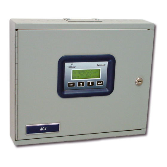
Outside Enclosure Overview The AC4’s controller board comes in an enclosure that is 2-3/4" deep and has a built-in liquid crystal display (LCD) and a key lock, as shown in Figure 1. The enclosure is made of metal to accommodate secure conduit fittings and protect components against environmental debris. -
Page 9: Typical Configuration
Introduction Typical Configuration Figure 3 shows an example of external devices connected to the AC4’s controller board. There may be up to four devices connected to the four digital inputs and four digital outputs. Remote access is avail- able through the Service Terminal Interface. -
Page 10: Controller Board Overview
Introduction Controller Board Overview The AC4’s controller board has connectors for four digital inputs and four digital outputs, as shown below. The board comes complete with light emitting diodes (LEDs) to display the status of connected devices, a serial communications port, a power connection and other features necessary to control your operation. - Page 11 Each of the four input connections is a two-state point: ON/ OFF (energized/de-energized). 3.2.1: Connecting Digital Inputs J - Digital input connectors An example of a field digital input is a Liebert 5.4: View Input Status Environmental unit’s common alarm relay output. 7.3:...
-
Page 12: Led Indicators
Introduction LED Indicators The AC4’s controller board has LED indicators that show the status of inputs, outputs and the com- mon alarm Output LEDs OUTPUT1 DS56 OUTPUT2 DS54 OUTPUT3 DS63 OUTPUT4 DS61 OUTPUT5 DS60 OUTPUT6 DS62 OUTPUT7 DS55 OUTPUT8 DS57... -
Page 13: Typical Sequence
Introduction Typical Sequence Figure 4 shows a typical sequence of how the AC4 functions after detecting a change in a monitored device. Many responses depend on configuration settings. This example shows what happens when a digital input changes state—assuming the input is defined as alarmable—and when the condition returns to normal. -
Page 14: Installation
NSTALLATION Installation Considerations The AC4 must be installed indoors and may be mounted on the surface of a wall or flush-mounted, depending on the user’s application, the location of equipment to be connected and the type of wall the unit will be mounted on. -
Page 15: Surface-Mounting The Ac4
1. Mark the wall for mounting holes, using the back of the unit as a template (see Figure 5). 2. Drill holes, if required, to install the four #10 screws that will secure the AC4 to the wall. Clean up the debris. -
Page 16: Flush-Mounting The Ac4
3. Use the saw to cut out the marked section of the wall (if not new construction). 4. Rest the AC4 in the wall and mark where mounting screws will be inserted into the wall studs or other support member. -
Page 17: Connect Power To The Ac4
(red & white) connector 3. Secure the incoming electrical service wires to the AC4’s 24VAC input by sliding the wires into TB7, the 24VAC input terminal block. There is no polarity requirement when connecting to TB7. The ground wire must be connected to the earth ground terminal located on the side of the panel... -
Page 18: Wiring And Connections
The Power On/Off switch is in the top left corner of the unit. Wiring Specifications Input and output connections to the AC4 may be made in any order—it is not necessary, for example, to make all input connections before making any output connections. Use copper conductors only for all wiring. -
Page 19: Connecting Digital Inputs And Outputs
• Input 3 is tied to Output 3 (default name: Device_3) • Input 4 is tied to Output 4 (default name: Device_4) Up to four devices may be connected to the AC4. Each device must be connected to an input and an output with the same number. -
Page 20: Setting The Digital Output Jumpers
Common alarm outputs 1. Turn OFF electrical power to the AC4. 2. If necessary, remove a conduit knockout to permit wire entry into the AC4 enclosure. 3. Bring the wire(s) into the AC4 enclosure through a conduit knockout or access slot. -
Page 21: Overview Of Menus
VERVIEW OF ENUS There are two ways to access the AC4: the LCD on the front of the enclosure and the Service Terminal Interface, which is accessible through any computer using a communications program. Many viewing and configuration tasks can be performed through either interface, but some are available only through the Service Terminal Interface. -
Page 22: Opening Screen Overview
Overview of Menus Opening Screen Overview The AC4 displays the Opening Screen at startup, as shown in Figure 7. • If any alarms are active, the Current Alarm screen appears. (Pressing any key on the LCD keypad will silence the audible alarm.) If no alarms are present, the Main Menu appears. -
Page 23: View Status Options
• View Input Status • View Output Status Figure 8 shows the main options available from the View Status menu. Figure 8 Menu overview - View Status menu Opening Screen LIEBERT AC4 DD-MON-YY HR:MM:SS VX.XXX.X PRESS =STATUS/SETUP Main Menu > VIEW STATUS... -
Page 24: View Active Alarms
View Status Options View Active Alarms Main Menu The Active Alarm screen displays all alarms that are occurring, up to a > VIEW STATUS maximum of 40. SYSTEM AND CONTROL A Current Alarm screen appears automatically whenever an alarm =NEXT =SELECT occurs—except during setup. -
Page 25: View Alarm Log
Backing Up the Alarm Log (Service Terminal Interface only) The alarm log is stored as a file in the AC4; it can hold no more than 99 records. When the log is full, the oldest records are deleted from the end of the file as new alarm records are added at the begin- ning. -
Page 26: View Event Log
Backing Up the Event Log (Service Terminal Interface only) The event log is stored as a file in the AC4; it can hold no more than 99 records. When the log is full, the oldest records are deleted from the end of the file as new event records are added at the beginning. -
Page 27: View Input Status
View Status Options View Input Status Main Menu The Input Status option allows you to view the current status of all four > VIEW STATUS digital inputs. SYSTEM AND CONTROL To view the Input Status: =NEXT =SELECT • From the Main Menu, use the arrows to choose View Status, then press Enter View Status Menu... -
Page 28: View Output Status
View Status Options View Output Status Main Menu The Output Status option allows you to view the current status of all > VIEW STATUS four outputs. SYSTEM AND CONTROL To view the Output Status: =NEXT =SELECT • From the Main Menu, use the arrows to choose View Status, then press Enter View Status Menu... -
Page 29: Silence Alarm & Backup Log Files (Service Terminal Interface )
AC4. The LCD does not offer Silence Alarm as a menu item. To silence the alarm remotely through the Service Terminal Interface: • Connect to the AC4 either from a remote computer or through the RS232 port (see A.2 - Connecting to the Service Terminal Interface). -
Page 30: Back Up Log Files (Service Terminal Interface Only)
Silence Alarm & Backup Log Files (Service Terminal Interface) Back Up Log Files (Service Terminal Interface only) The AC4 maintains two types of logs—alarm and event—that may be backed up to a remote com- puter. This feature is available only through the Service Terminal Interface. - Page 31 (return to Step 3) or press 3 (or Escape) to return to the Main Menu. After backing up a log file, you may want to delete all records in the AC4’s log of that type. See 7.10 - Clear Alarms & Logs for details.
-
Page 32: System And Control Options
The System and Control menu allows you to configure the AC4—setting up inputs and outputs and system features such as date and time. This menu also provides a vehicle for manually changing the state of an output to ON or OFF, clearing active alarms and deleting records from the AC4’s alarm and event logs. -
Page 33: Figure 9 Menu Overview - System And Control Menu
System and Control Options Figure 9 shows the main options available from the System & Control menu. Figure 9 Menu overview - System and Control menu Opening Screen LIEBERT AC4 DD-MON-YY HR:MM:SS VX.XXX.X PRESS =STATUS/SETUP Main Menu VIEW STATUS > SYSTEM AND CONTROL... -
Page 34: Setup System - Overview
Events are always Unlatched. • You may also specify a time delay before the AC4 responds to an alarm or event. Use the steps following Table 13 to change the default settings for any digital input. -
Page 35: Change Label (Name Of Input)
System and Control Options 7.3.1 Change Label (Name of Input) Setup Inputs Menu Each input has a default label (Device_1, Device_2, etc.) that you may SETUP DEVICE_1 change to a more descriptive name for ease in recognizing alarms and > LABEL: DEVICE_1 events associated with the input. -
Page 36: Set Up Alarmable Inputs In Latched Or Unlatched Mode
Alarmable input points may be set up in Latched mode (Y), which SETUP DEVICE_1 requires the user to clear the AC4 alarms after an alarm has occurred, LABEL: DEVICE_1 or Unlatched mode (N), in which alarms will automatically clear after... -
Page 37: Setup System - Setup Common Alarm
System and Control Options Setup System - Setup Common Alarm The audible alarm sounds after the AC4 detects an alarm condition in any input that has been defined as alarmable. Once the alarm is silenced, there are two options: • By default, the common alarm remains energized until all input alarms are cleared. -
Page 38: Setup System - Setup Zones
System and Control Options Setup System - Setup Zones The AC4 has two zones that may be used to define different areas—rooms or sections of a room. The AC4 effectively performs as two separate units, controlling each zone separately, for examply, using a different rotation sequence for devices in each zone. -
Page 39: Setup System - Setup Outputs
System and Control Options Setup System - Setup Outputs The AC4 has four outputs that may be configured individually. These outputs correspond to the four numbered inputs. For example, Device_1 is the unit connected to Input 1 and to Output 1. -
Page 40: Define Operating Or Standby Mode
System and Control Options 7.6.2 Define Operating or Standby Mode Setup Outputs Menu Each output may be defined as Operating (OP), Standby (ST), or Not SETUP DEVICE_1 Used (NU). This setting takes precedence over any setting in the over- NORM OPEN/CLOSE: NO ride menu (see 7.9 - Override Output). -
Page 41: Setup System - Setup System Info
• Set Date & Time/Automatic Daylight Saving Time—used to set the AC4’s date and time and to enable automatic time change for Daylight Saving Time • Setup Site ID—the AC4’s location to differentiate among sites if more than one AC4 is in use • Backup and Upload Configuration File (Service Terminal Interface only)—permits the user to copy the AC4’s configuration settings and to upload the file to the AC4... -
Page 42: Set Date & Time/Automatic Daylight Saving Time
Set Date & Time/Automatic Daylight Saving Time The AC4 has a built-in real-time clock that is backed up by an encapsulated lithium battery and set up to adjust automatically for daylight saving time twice a year. The Setup System Info menu allows you to set the current date or time or change the automatic adjustment at any time. -
Page 43: Backup And Upload Configuration File (Service Terminal Interface Only)
SELECT A NUMBER:1 6. Enter 1 to back up the configuration file from the AC4 to the computer and proceed to Step 8, 7. Enter 2 to upload the configuration file from the computer to the AC4 and proceed to Step 13. - Page 44 System and Control Options Back Up the Configuration File 8. At the prompt to Initiate a Backup of Configuration File, enter Y (Yes - begin) or N (No - cancel). The current setting appears in brackets—[N] in the following example. >INITIATE A BACKUP OF CONFIGURATION FILE-YES(Y) OR NO(N)? >[N] >[...
- Page 45 • Click on the Send button. (To close the window without sending the file, click on Close or Cancel.) 16. When the transfer is complete, a confirmation message—“Upload Successful”—appears in the Service Terminal Interface window and the AC4 reboots with the new configuration.
-
Page 46: Factory Defaults
Terminal Interface only) in A.6.5 - Setup System Info for details on backing up settings using the Service Terminal Interface. • Connect to the AC4 either from a remote computer or through the RS232 port (see A.2 - Connecting to the Service Terminal Interface). - Page 47 • Click on the Send button. (To close the window without sending the file, click on Close or Cancel.) • When the transfer is complete, a confirmation message—“Firmware Update Successful”— appears in the Service Terminal Interface window and the AC4 reboots with the new firmware update.
-
Page 48: Setup Operation
System and Control Options Setup Operation The AC4’s operation features allow you to set up a rotation sequence to Setup System Menu alternate which devices are operating and which are placed on Standby, as well as test devices while in Standby mode and specify... -
Page 49: Turn Automatic Sequencing On Or Off
Use automatic sequencing to set up a schedule for rotation of redundant devices. For example, three devices might be in operating mode while a fourth device is in standby mode. Every two days, the AC4 returns the standby device to operating mode and places one of the operating devices on standby. -
Page 50: Turn Standby Testing On Or Off
Standby testing permits scheduling an automatic operational check of devices in Standby mode. When this feature is activated (ON), the AC4 tests all devices in Standby mode by putting each device in operating mode for a designated time. You may specify the time of day the testing begins, the dura- tion of the test and the interval between tests. -
Page 51: Specify Hold Delay Time
=NEXT =EDIT The hold delay timer also takes effect when the AC4 is powered up. All alarms are ignored until the hold delay time expires. • From the Setup Operation Menu, choose Hold Delay, as shown at right, and press Enter . -
Page 52: Override Output
The Override Output feature allows you to manually change the state of any digital output to ON or OFF, overriding automatic control by the AC4 (the default setting for all outputs). This menu also allows you to release the manual override, returning any output to automatic control. -
Page 53: Clear Alarms & Logs
7.10.3 Clear the Event Log CLEAR ACTIVE ALARMS The event log contains up to 99 records of events detected by the AC4. CLEAR ALARM LOG You may want to clear the log after backing up the file or simply to free >... -
Page 54: Specifications
Specifications PECIFICATIONS AC4 Specifications NOTE 24VAC ±10% of nominal Power Requirements 50/60 Hz If the equipment is 1.3A, 30VA used in a manner 14-1/4 x 2-3/4 x 12 not specified by the Dimensions W x D x H, in. (mm) (361.95 x 69.85 x 304.8) -
Page 55: Comparison Of Functions: Lcd And Service Terminal Interface
UNCTIONS ERVICE ERMINAL NTERFACE Table 21 lists all functions for viewing and configuring the AC4 and shows whether they can be per- formed through the LCD interface and where to find information. Table 21 Guide to AC4 functions Can be performed via:... -
Page 56: Connecting To The Service Terminal Interface
This section describes how to set up and connect to the Service Terminal Interface. To access the Ser- vice Terminal Interface, you will need: • A null modem cable to connect a computer’s COM1 port to the AC4’s RS232 port. • A communications program, such as HyperTerminal, to connect to the Service Terminal Interface. -
Page 57: Create A Connection
- for example, AC4 3. In the Connection Description window, shown above right, enter a name for the connection—for example, AC4. This becomes the file name (with the extension “.ht”). 4. Click OK to close the window. The Connect To window opens, as shown at right. - Page 58 Connecting to the Service Terminal Interface Properties Setup 9. Open the Properties window by clicking on File, then on Properties, as shown below left. Settings 10. In the Properties window, above right, click on the Settings tab and choose the following settings: •...
-
Page 59: Connect To The Service Terminal Interface
2. Start the HyperTerminal program—click on the Start button, then on Programs, then Accessories, then Communications, and finally HyperTerminal. 3. Open the AC4 connection created in A.2.1 - Create a Connection. To do this, click on File, then on Open, as shown below. -
Page 60: Overview Of Menus
VERVIEW OF ENUS The Main Menu offers choices for viewing the status of the AC4, silencing the audible alarm and backing up the unit’s log files. It also allows access to the System and Control features, which require a password. -
Page 61: View Status Menus
After connecting to the Service Terminal Interface, the Main Menu appears, as shown below. This section presents Service Terminal Interface screens for options 1 through 5: Main Menu LIEBERT AC4 VX.XXX.X LIEBERT CORPORATION COPYRIGHT 2004 ALL RIGHTS RESERVED MAIN MENU For sample screens, see: Section A.4.1 1=VIEW ACTIVE ALARMS Section A.4.2... -
Page 62: View Active Alarms
View Status Menus A.4.1 View Active Alarms For details on this feature, see 5.1 - View Active Alarms. View Active Alarms ACTIVE ALARMS Input points/hardware presently in an alarm state DEVICE_1 ALARM CONTACT CLOSED 1=REFRESH ACTIVE ALARMS 2=RETURN TO MAIN MENU SELECT A NUMBER:... -
Page 63: View Alarm Log
View Status Menus A.4.2 View Alarm Log For details on this feature, see 5.2 - View Alarm Log. View Alarm Log ALARM LOG Alarm history DEVICE_1 ALARM CONTACT CLOSED 29-AUG-02 09:29:10 NO STANDBY AVAILABLE 29-AUG-02 09:20:10 STANDBY DEVICE FAILED 29-AUG-02 09:19:10 NO RESTART AVAILABLE 29-AUG-02... -
Page 64: View Event Log
View Status Menus A.4.3 View Event Log For details on this feature, see 5.3 - View Event Log. View Event Log EVENT LOG Event history SYSTEM USER LOGIN 07-MAY-02 10:29:10 DEVICE_1 HW FORCE ON CONTACT CLOSED 07-MAY-02 09:50:10 DEVICE_4 FORCE OFF CONTACT OPEN 07-MAY-02 09:20:10... -
Page 65: View Input Status
View Status Menus A.4.4 View Input Status For details on this feature, see 5.4 - View Input Status. View Input Status INPUT STATUS Input status from device INPUT STATUS DEVICE_1 NORMAL DEVICE_2 ALARM DEVICE_3 EVENT DEVICE_4 ALARM 1=REFRESH INPUT 2=RETURN TO MAIN MENU SELECT A NUMBER:1... -
Page 66: View Output Status
View Status Menus A.4.5 View Output Status For details on this feature, see 5.5 - View Output Status. View Output Status OUTPUT STATUS Output status to device OUTPUT STATE MODE ZONE ***************************************** OPERATING = OPERATING/ON DEVICE_1 ALARM STANDBY = IN STANDBY MODE DEVICE_2 OPERATING ALARM... -
Page 67: Silence Alarm & Back Up Log Files (Service Terminal Interface Only)
After connecting to the Service Terminal Interface, the Main Menu appears, as shown below. This section presents Service Terminal Interface screens for options 6 and 7: Main Menu LIEBERT AC4 V5.300.2 LIEBERT CORPORATION COPYRIGHT 2004 ALL RIGHTS RESERVED MAIN MENU 1=VIEW ACTIVE ALARMS 2=VIEW ALARM LOG... -
Page 68: Back Up Log Files (Service Terminal Interface Only)
Silence Alarm & Back Up Log Files (Service Terminal Interface only) A.5.2 Back Up Log Files (Service Terminal Interface only) For details on this feature, see 6.2 - Back Up Log Files (Service Terminal Interface only). Back Up Alarm Log File Backup Log Files - Alarm Log File BACKUP LOG FILES Backup alarm and event log files... -
Page 69: Setup Menu
A.6 S ETUP The Setup menu allows the user to configure the AC4—setting up inputs, outputs and system fea- tures such as date and time, as well as operation options such as a rotation sequence and standy test- ing. This menu also provides a vehicle for manually changing the state of an output to ON or OFF, clearing active alarms and deleting records from the AC4’s alarm and event logs. - Page 70 Setup Menu Setup Menu This section presents Service Terminal Interface screens for each of the following: Setup Menu See: Description SETUP MENU Section A.6.1 Configure digital inputs 1=SETUP INPUTS Section A.6.2 Set up the common alarm to reset with silence 2=SETUP COMMON ALARM Section A.6.3 Define areas with 2-4 devices each...
-
Page 71: Setup Inputs
Setup Menu A.6.1 Setup Inputs For details on this feature, see 7.3 - Setup System - Setup Inputs. Setup Inputs SETUP INPUTS Setup input of device Select input to edit INPUT DEFINITION **************************** NO=NORMALLY OPENED 1=DEVICE_1 NO-EV-NL-00:01 NC=NORMALLY CLOSED 2=DEVICE_2 NO-AL-L -00:01 3=DEVICE_3 NC-EV-NL-00:01... -
Page 72: Setup Common Alarm
Setup Menu A.6.2 Setup Common Alarm For details on this feature, see 7.4 - Setup System - Setup Common Alarm. Setup Common Alarm SETUP COMMON ALARM Select if the common alarm relay contact is to reset with silence alarm CURRENT SETTING 1=SETUP COMMON ALARM 2=RETURN TO SETUP MENU... -
Page 73: Setup Zones
Setup Menu A.6.3 Setup Zones For details on this feature, see 7.5 - Setup System - Setup Zones. Setup Zones SETUP ZONES Select zones and number of devices in the zone ZONE # DEVICES 1=ZONE 1 2=ZONE 2 3=RETURN TO SETUP MENU 4=RETURN TO MAIN MENU SELECT A NUMBER:1 ># DEVICES IN ZONE 1... -
Page 74: Setup Outputs
Setup Menu A.6.4 Setup Outputs For details on this feature, see 7.6 - Setup System - Setup Outputs. Setup Outputs SETUP OUTPUTS Setup output of device Select output to edit OUTPUT DEFINITION ******************************************* NO=NORMALLY OPENED 1=DEVICE_1 NO-OP-E NC=NORMALLY CLOSED 2=DEVICE_2 NO-ST-E 3=DEVICE_3 NO-NU-D... -
Page 75: Setup System Info
Setup Menu A.6.5 Setup System Info This section presents Service Terminal Interface screens for choices 1 through 9 in the Setup System Information menu shown below. For details on this topic, see 7.7 - Setup System - Setup System Info. Setup System Info SETUP SYSTEM INFORMATION 1=CHANGE PASSWORD... - Page 76 Setup Menu Set Date & Time/Automatic Daylight Saving Time For details on this feature, see 7.7.2 - Set Date & Time/Automatic Daylight Saving Time. Set Date & Time SET DATE & TIME CURRENT DATE & TIME 28-AUG-04 14:45:10 1=SET DATE & TIME 2=RETURN TO SETUP SYSTEM INFO MENU 3=RETURN TO SETUP MENU 4=RETURN TO MAIN MENU...
- Page 77 Setup Menu Backup and Upload Configuration File (Service Terminal Interface only) For details on this feature, see 7.7.4 - Backup and Upload Configuration File (Service Termi- nal Interface only). Backup & Upload Configuration File - Backup BACKUP AND UPLOAD CONFIGURATION FILE Backup from panel saves panel configurations Upload to panel restores panel configurations Select to backup or upload file...
- Page 78 Setup Menu Backup & Upload Configuration File - Upload BACKUP AND UPLOAD CONFIGURATION FILE Backup from panel saves panel configurations Upload to panel restores panel configurations Select to backup or upload file 1=BACKUP CONFIGURATION FILE 2=UPLOAD CONFIGURATION FILE 3=RETURN TO SETUP SYSTEM INFO MENU 4=RETURN TO SETUP MENU 5=RETURN TO MAIN MENU SELECT A NUMBER:2...
- Page 79 Setup Menu Firmware Update (Service Terminal Interface only) For details on this feature, see 7.7.6 - Perform Firmware Update (Service Terminal Interface only). Firmware Update PERFORM FIRMWARE UPDATE This command will update the existing firmware 1=PERFORM FIRMWARE UPDATE 2=RETURN TO SETUP SYSTEM INFO MENU 3=RETURN TO SETUP MENU 4=RETURN TO MAIN MENU SELECT A NUMBER:1...
-
Page 80: Setup Operation
Setup Menu A.6.6 Setup Operation For details on this feature, see 7.8 - Setup Operation. Auto Sequencing For details on this feature, see 7.8.1 - Turn Automatic Sequencing On or Off. Setup Operation - Auto Sequencing SETUP OPERATION Select operation to edit OPERATION STATE 1=AUTO SEQUENCING... - Page 81 Setup Menu Standby Testing For details on this feature, see 7.8.2 - Turn Standby Testing On or Off. Setup Operation - Standby Testing SETUP OPERATION Select operation to edit OPERATION STATE 1=AUTO SEQUENCING 2=STANDBY TESTING 3=FAILED STANDBY 4=HOLD DELAY 10:00 5=RESTART DELAY 00:06 6=RETURN TO SETUP MENU...
- Page 82 Setup Menu Failed Standby For details on this feature, see 7.8.3 - Specify Failed Standby Response. Setup Operation - Failed Standby SETUP OPERATION Select operation to edit OPERATION STATE 1=AUTO SEQUENCING 2=STANDBY TESTING 3=FAILED STANDBY 4=HOLD DELAY 10:00 5=RESTART DELAY 00:06 6=RETURN TO SETUP MENU 7=RETURN TO MAIN MENU...
- Page 83 Setup Menu Restart Delay For details on this feature, see 7.8.5 - Specify Restart Time. Setup Operation - Restart Delay SETUP OPERATION Select operation to edit OPERATION STATE 1=AUTO SEQUENCING 2=STANDBY TESTING 3=FAILED STANDBY 4=HOLD DELAY 10:00 5=RESTART DELAY 00:06 6=RETURN TO SETUP MENU 7=RETURN TO MAIN MENU SELECT A NUMBER:5...
-
Page 84: Override Output
Setup Menu A.6.7 Override Output For details on this feature, see 7.9 - Override Output. Override Output OVERRIDE OUTPUT Manually override an output point Select output to override OUTPUT CONTROL 1=DEVICE_1 AUTO ******************************** 2=DEVICE_2 AUTO AUTO = CONTROL BY PANEL 3=DEVICE_3 FORCE ON FORCE ON = FORCE ON BY OPERATOR... -
Page 85: Clear Alarms & Logs
Setup Menu A.6.8 Clear Alarms & Logs For details on this topic, see 7.10 - Clear Alarms & Logs. Clear Active Alarms For details on this feature, see 7.10.1 - Clear Active Alarms. Clear Alarms & Logs - Clear Active Alarms CLEAR ALARMS&LOGS Clear active alarms or log records... - Page 86 Setup Menu Clear the Event Log For details on this feature, see 7.10.3 - Clear the Event Log. Clear Alarms & Logs - Clear the Event Log CLEAR ALARMS&LOGS Clear active alarms or log records Select the log to clear 1=CLEAR ACTIVE ALARMS 2=CLEAR ALARM LOG 3=CLEAR EVENT LOG...
- Page 88 The Company Behind the Products Technical Support/Service Web Site With over a million installations around the globe, www.liebert.com Liebert is the world leader in computer protection Monitoring systems. Since its founding in 1965, Liebert has 800-222-5877 developed a complete range of support and monitoring@liebert.com...