Sign In
Upload
Manuals
Brands
Intel Manuals
Server Board
S3210SH
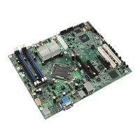
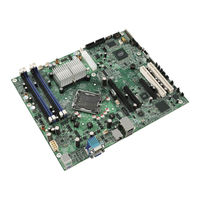
Intel S3210SH Manuals
Manuals and User Guides for Intel S3210SH. We have
3
Intel S3210SH manuals available for free PDF download: Specification, Overview & Operation
Intel S3210SH Specification (128 pages)
Product Specification
Brand:
Intel
| Category:
Motherboard
| Size: 1.81 MB
Table of Contents
Revision History
2
Table of Contents
3
1 Introduction
13
Chapter Outline
13
Server Board Use Disclaimer
13
2 Server Board Overview
14
Server Board Feature Set
14
Figure 1. Intel
19
Table 1. Intel
19
Figure 2. Intel
20
Table 2. Intel
20
Figure 3. Intel
21
Server Board Layout
22
Figure 4. Intel Server Board S3210SHLC
22
Figure 5. Intel Server Board S3210SHLX - Hole and Component Positions
23
Server Board Mechanical Drawings
23
Figure 6. Intel ® Server Boards S3210SHLC/S3200SHL/S3200SHV - Hole and Component
24
3 Functional Architecture
25
Figure 7. Intel Server Boards S3200SH/S3210SH LC/L/V SKU-Block Diagram
25
Figure 8. Intel Server Systems S3200SH/S3210SH LX SKU-Block Diagram
26
Processor Sub-System
27
Processor Voltage Regulator down (VRD)
27
Reset Configuration Logic
27
Intel 3200/3210 Chipset
28
Intel ® 3200/3210 Chipset MCH: Memory Control Hub
28
Table 3. Processor Support Matrix
28
Table 4. Segment F Connections
29
Table 5. Supported DDR2 Modules
30
PCI-X Hub (LX Board SKU Only)
31
Table 6. Segment E Configuration Ids
31
Table 7. Segment D Arbitration Connections
31
Intel ICH9R: I/O Controller Hub 9R
32
Table 8. Boot BIOS Destination Selection
35
Table 9. SPI Required Command Codes
35
Memory Sub-System
38
Memory Configuration
38
Figure 9. Memory Bank Label Definition
39
Table 10. Memory Bank Labels and DIMM Population Order
39
Memory DIMM Support
40
I/O Sub-System
40
PCI Subsystem
40
Table 12. PCI Bus Segment Characteristics
41
Table 13. Segment a Configuration Ids
41
Interrupt Routing
42
Table 14. Segment a Arbitration Connections
42
Table 15. PCI and PCI-X Interrupt Routing/Sharing
42
Table 16. Interrupt Definitions
43
Figure 10. Interrupt Routing Diagram
45
Figure 11. Intel ICH9R Interrupt Routing Diagram
46
Figure 12. PXH-V Interrupt Routing Diagram
47
BMC Controller
48
Clock Generator
50
PCI Express* to PCI-X Bridge 6702PXH (PXH-V) (LX Board SKU Only)
50
Super I/O
50
3.10 Gige PHY
51
3.11 On-Board Components
51
Video Support
51
Table 17. Video Modes
53
Gige Controller 82541PI
51
3.12 Replacing the Back-Up Battery
54
4 System BIOS
55
BIOS Identification String
55
Logo / Diagnostic Window
56
BIOS Setup Utility
56
Operation
56
Table 18. BIOS Setup Page Layout
57
Table 19. BIOS Setup: Keyboard Command Bar
58
Server Platform Setup Screens
59
Figure 13. Setup Utility - Main Screen Display
60
Table 20. Setup Utility - Main Screen Fields
61
Figure 14. Setup Utility - Advanced Screen Display
62
Figure 15. Setup Utility - Processor Configuration Screen Display
63
Table 21. Setup Utility - Advanced Screen Display Fields
63
Table 22. Setup Utility - Processor Configuration Screen Fields
64
Figure 16. Setup Utility - Memory Configuration Screen Display
65
Table 23. Setup Utility - Memory Configuration Screen Fields
65
Figure 17. Setup Utility - ATA Controller Configuration Screen Display
67
Table 24. Setup Utility - ATA Controller Configuration Screen Fields
68
Figure 18. Setup Utility - Serial Port Configuration Screen Display
69
Table 25. Setup Utility - Serial Ports Configuration Screen Fields
69
Figure 19. Setup Utility - USB Controller Configuration Screen Display
70
Table 26. Setup Utility - USB Controller Configuration Screen Fields
71
Figure 20. Setup Utility - PCI Configuration Screen Display
72
Table 27. Setup Utility - PCI Configuration Screen Fields
72
Figure 21. Setup Utility - Security Configuration Screen Display
73
Table 28. Setup Utility - Security Configuration Screen Fields
73
Figure 22. Setup Utility - Server Management Configuration Screen Display
74
Table 29. Setup Utility - Server Management Configuration Screen Fields
74
Figure 23. Setup Utility - Console Redirection Screen Display
76
Table 30. Setup Utility - Console Redirection Configuration Fields
76
Figure 24. Setup Utility - Server Management System Information Screen Display
77
Table 31. Setup Utility - Server Management System Information Fields
77
Figure 25. Setup Utility - Boot Options Screen Display
78
Figure 26. Setup Utility - Hard Disk Order Screen Display
79
Table 32. Setup Utility - Boot Options Screen Fields
79
Table 33. Setup Utility - Hard Disk Order Fields
80
Figure 27. Setup Utility - CDROM Order Screen Display
81
Figure 28. Setup Utility - Floppy Order Screen Display
81
Table 34. Setup Utility - CDROM Order Fields
81
Figure 29. Setup Utility - Network Device Order Screen Display
82
Table 35. Setup Utility - Floppy Order Fields
82
Table 36. Setup Utility - Network Device Order Fields
82
Figure 30. Setup Utility - BEV Device Order Screen Display
83
Table 37. Setup Utility - BEV Device Order Fields
83
Figure 31. Setup Utility - Boot Manager Screen Display
84
Figure 32. Setup Utility - Error Manager Screen Display
84
Table 38. Setup Utility - Boot Manager Screen Fields
84
Figure 33. Setup Utility - Exit Screen Display
85
Table 39. Setup Utility - Error Manager Screen Fields
85
Table 40. Setup Utility - Exit Screen Fields
85
Loading BIOS Defaults
87
Multiple Boot Blocks
87
Recovery Mode
87
Intel Matrix Storage Manager
88
Intel ® Embedded Server RAID Technology II Support
88
5 Error Reporting and Handling
89
Error Handling and Logging
89
Error Sources and Types
89
Table 41. Event List
89
Error Logging Via SMI Handler
90
SMBIOS Type 15
90
Logging Format Conventions
90
Table 42. SMBIOS Type 15 Event Log Record Format
91
Table 43. Event Type Definition Table
91
Error Messages and Error Codes
92
Diagnostic Leds
92
POST Code Checkpoints
93
Figure 34. Example of Diagnostic Leds on Server Board
93
Table 44. POST Progress Code LED Example
93
Table 45. POST Code Checkpoints
93
POST Error Messages and Handling
96
Table 46. POST Error Messages and Handling
96
POST Error Beep Codes
97
POST Error Pause Option
97
Table 47. POST Error Beep Codes
97
6 Connectors and Jumper Blocks
98
Power Connectors
98
Main Power Connector
98
Table 48. Power Connector Pin-Out (J4G1)
98
Table 49. Auxiliary CPU Power Connector Pin-Out (J9B2)
98
Intel Riser Card for L SKU
99
Smbus Connector
99
Front Panel Connector
99
Table 50. Smbus Connector Pin-Out (J1E1)
99
Table 51. Front Panel 24-Pin Header Pin-Out (J1K2)
99
I/O Connectors
100
VGA Connector
100
NIC Connectors
100
Table 52. VGA Connector Pin-Out (J8B1)
100
Table 53. NIC2-Intel ® 82541PI (10/100/1000) Connector Pin-Out (J5B1)
100
SATA Connectors
101
Floppy Controller Connector
101
Table 54. NIC1- Intel ® 82566E (10/100/1000) Connector Pin-Out (J6B1)
101
Table 55. SATA Connector Pin-Out (J2K1, J1K1, J1J3, J1H3, J1H2, J1H1)
101
Table 56. Legacy 34-Pin Floppy Connector Pin-Out (J3K1)
101
Serial Port Connectors
102
Table 57. External DB9 Serial a Port Pin-Out (J8B1)
102
Keyboard and Mouse Connector
103
USB Connector
103
Table 58. Keyboard and Mouse PS/2 Connectors Pin-Out (J9A1)
103
Table 59. USB Connectors Pin-Out (J5B1)
103
Fan Headers
104
Miscellaneous Headers and Connectors
104
Back Panel I/O Connectors
104
Figure 35. Intel ® Server Board S3210SHLX / S3210SHLC / S3200SHL Back Panel I/O Connectors
104
Table 60. Optional USB Connection Header Pin-Out (J1G1)
104
Table 61. Four-Pin Fan Headers Pin-Out (J4D1, J1K2, J7K1, and J4K1J6B2)
104
Chassis Intrusion Header
105
HDD Active LED Header
105
Ipmb
105
Hsbp
105
Figure 36. Intel ® Server Board S3200SHV Back Panel I/O Connectors
105
Table 62. Chassis Intrusion Header (J1B2) Pin-Out
105
Table 63. HDD LED Header (J1J1) Pin-Out
105
Sata Sgpio
106
Jumper Blocks
106
CMOS Clear and Password Reset Usage Procedure
106
BMC Force Update Procedure
107
7 Absolute Maximum Ratings
108
Mean Time between Failures (MTBF) Test Results
108
Calculated Mean Time between Failures (MTBF)
108
Table 64. Absolute Maximum Ratings
108
Table 65. MTBF Data
108
8 Design and Environmental Specifications
109
Power Budget
109
Table 66. Power Budget
109
Power Supply Specifications
110
Power Timing Requirements
110
Table 67. Server Board Power Supply Voltage Specification
110
Table 68. Output Voltage Timing
110
Figure 37. Output Voltage Timing
111
Figure 38. Turn On/Off Timing (Power Supply Signals)
112
Table 69. Turn On/Off Timing
112
Dynamic Loading
113
AC Line Transient Specification
113
Table 70. Transient Load Requirements
113
Table 71. AC Line Sag Transient Performance
113
AC Line Fast Transient (EFT) Specification
114
Product Regulatory Compliance
114
Product Safety Compliance
114
Table 72. AC Line Surge Transient Performance
114
Product EMC Compliance - Class a Compliance
115
Certifications / Registrations / Declarations
115
Product Regulatory Compliance Markings
117
Table 73. Product Certification Markings
117
Electromagnetic Compatibility Notices
118
Fcc (Usa)
118
ICES-003 (Canada)
119
Europe (CE Declaration of Conformity)
119
VCCI (Japan)
119
Taiwan Declaration of Conformity (BSMI)
119
Korean Compliance (RRL)
120
Mechanical Specifications
121
Figure 39. Intel Server Board S3200SH Mechanical Drawing
121
Figure 40. Pedestal Mount I/O Shield Mechanical Drawing for the Intel ® Server Board S3200SH- V
122
Figure 41. Pedestal Mount I/O Shield Mechanical Drawing for Intel Server Boards S3200SH
123
9 Hardware Monitoring
124
Chassis Intrusion
124
Glossary
125
Revision
128
Reference Documents
128
Advertisement
Intel S3210SH Specification (128 pages)
Product Specification
Brand:
Intel
| Category:
Server Board
| Size: 1.53 MB
Table of Contents
Revision History
2
Table of Contents
4
1 Introduction
15
Chapter Outline
15
Server Board Use Disclaimer
15
2 Server Board Overview
16
Server Board Feature Set
16
Figure 1. Intel
22
Table 1. Intel
22
Figure 2. Intel
23
Figure 3. Intel
23
Server Board Layout
24
Figure 4. Intel Server Board S3210SHLC
24
Figure 5. Intel Server Board S3210SHLX - Hole and Component Positions
25
Server Board Mechanical Drawings
25
Figure 6. Intel ® Server Boards S3210SHLC/S3200SHL/S3200SHV - Hole and Component
26
Positions
26
3 Functional Architecture
27
Block Diagram
28
Processor Sub-System
30
Processor Voltage Regulator down (VRD)
30
Reset Configuration Logic
30
Intel 3200/3210 Chipset
31
Intel ® 3200/3210 Chipset MCH: Memory Control Hub
31
Table 3. Processor Support Matrix
31
Table 4. Segment F Connections
33
Table 5. Supported DDR2 Modules
33
PCI-X* Hub (PXH)
34
Intel ® ICH9R: I/O Controller Hub 9R
35
Table 6. Segment E Configuration Ids
35
Table 7. Segment D Arbitration Connections
35
Table 8 Boot BIOS Destination Selection
38
Table 9: SPI Required Command Codes
39
Memory Sub-System
41
Memory Configuration
41
Table 10. Memory Bank Labels and DIMM Population Order
42
Figure 7. Memory Bank Label Definition
43
Memory DIMM Support
44
I/O Sub-System
44
PCI Subsystem
44
Table 12. PCI Bus Segment Characteristics
44
Table 13. Segment a Configuration Ids
45
Table 14. Segment a Arbitration Connections
45
Interrupt Routing
46
Table 15. PCI and PCI-X* Interrupt Routing/Sharing
46
Table 16. Interrupt Definitions
47
Figure 8. Interrupt Routing Diagram
48
Figure 9. Intel ICH9R Interrupt Routing Diagram
49
Figure 10. PXH-V Interrupt Routing Diagram
50
BMC Controller
51
Pcie* to PCI-X* Bridge 6702PXH (PXH-V) (LX Board SKU Only)
52
Clock Generator
53
Gige Controller 82541PI
53
Super I/O
53
3.10 Gige PHY
54
3.11 on Board Components
54
Video Support
54
Table 17. Video Modes
55
3.12 Replacing the Back-Up Battery
56
4 System BIOS
57
BIOS Identification String
57
Logo / Diagnostic Window
58
BIOS Setup Utility
58
Operation
58
Table 18. BIOS Setup Page Layout
59
Table 19. BIOS Setup: Keyboard Command Bar
60
Server Platform Setup Screens
61
Figure 11. Setup Utility - Main Screen Display
62
Table 20. Setup Utility - Main Screen Fields
63
Figure 12. Setup Utility - Advanced Screen Display
64
Table 21. Setup Utility - Advanced Screen Display Fields
65
Figure 13. Setup Utility - Processor Configuration Screen Display
66
Table 22. Setup Utility - Processor Configuration Screen Fields
66
Figure 14. Setup Utility - Memory Configuration Screen Display
68
Table 23. Setup Utility - Memory Configuration Screen Fields
68
Figure 15. Setup Utility - ATA Controller Configuration Screen Display
69
Table 24. Setup Utility - ATA Controller Configuration Screen Fields
70
Figure 16. Setup Utility - Serial Port Configuration Screen Display
71
Table 25. Setup Utility - Serial Ports Configuration Screen Fields
71
Figure 17. Setup Utility - USB Controller Configuration Screen Display
72
Table 26. Setup Utility - USB Controller Configuration Screen Fields
73
Figure 18. Setup Utility - PCI Configuration Screen Display
74
Table 27. Setup Utility - PCI Configuration Screen Fields
74
Figure 19. Setup Utility - Security Configuration Screen Display
75
Table 28. Setup Utility - Security Configuration Screen Fields
75
Figure 20. Setup Utility - Server Management Configuration Screen Display
76
Table 29. Setup Utility - Server Management Configuration Screen Fields
76
Figure 21. Setup Utility - Console Redirection Screen Display
78
Table 30. Setup Utility - Console Redirection Configuration Fields
78
Figure 22. Setup Utility - Server Management System Information Screen Display
79
Table 31. Setup Utility - Server Management System Information Fields
79
Figure 23. Setup Utility - Boot Options Screen Display
80
Table 32. Setup Utility - Boot Options Screen Fields
80
Figure 24. Setup Utility - Hard Disk Order Screen Display
81
Table 33. Setup Utility - Hard Disk Order Fields
81
Figure 25. Setup Utility - CDROM Order Screen Display
82
Figure 26. Setup Utility - Floppy Order Screen Display
82
Table 34. Setup Utility - CDROM Order Fields
82
Figure 27. Setup Utility - Network Device Order Screen Display
83
Table 35. Setup Utility - Floppy Order Fields
83
Table 36. Setup Utility - Network Device Order Fields
83
Figure 28. Setup Utility - BEV Device Order Screen Display
84
Table 37. Setup Utility - BEV Device Order Fields
84
Figure 29. Setup Utility - Boot Manager Screen Display
85
Figure 30. Setup Utility - Error Manager Screen Display
85
Table 38. Setup Utility - Boot Manager Screen Fields
85
Figure 31. Setup Utility - Exit Screen Display
86
Table 39. Setup Utility - Error Manager Screen Fields
86
Table 40. Setup Utility - Exit Screen Fields
86
Loading BIOS Defaults
88
Multiple Boot Blocks
88
Recovery Mode
88
Intel ® Matrix Storage Manager
89
Intel ® Embedded Server RAID Technology II Support
89
5 Error Reporting and Handling
90
Error Handling and Logging
90
Error Sources and Types
90
Table 41. Event List
90
Error Logging Via SMI Handler
91
SMBIOS Type 15
91
Logging Format Conventions
91
Table 42. SMBIOS Type 15 Event Log Record Format
92
Table 43. Event Type Definition Table
92
Error Messages and Error Codes
93
Diagnostic Leds
93
POST Code Checkpoints
94
Table 44.: POST Progress Code LED Example
94
Table 45. POST Code Checkpoints
94
POST Error Messages and Handling
97
POST Error Beep Codes
98
POST Error Pause Option
98
Table 46. POST Error Messages and Handling
98
Table 47. POST Error Beep Codes
98
6 Connectors and Jumper Blocks
99
Power Connectors
99
Main Power Connector
99
Table 48. Power Connector Pin-Out (J4G1)
99
Table 49. Auxiliary CPU Power Connector Pin-Out (J9B2)
99
Intel ® Riser Card for L SKU
100
Smbus Connector
100
Front Panel Connector
100
Table 2. Intel
100
Table 50. Smbus Connector Pin-Out (J1E1)
100
Table 51. Front Panel 24-Pin Header Pin-Out (J1K2)
100
I/O Connectors
101
VGA Connector
101
NIC Connectors
101
Table 52. VGA Connector Pin-Out (J8B1)
101
Table 53. NIC2-Intel ® 82541PI (10/100/1000) Connector Pin-Out (J5B1)
101
SATA Connectors
102
Floppy Controller Connector
102
Table 54. NIC1- Intel ® 82566E (10/100/1000) Connector Pin-Out (J6B1)
102
Table 55. SATA Connector Pin-Out (J2K1, J1K1, J1J3, J1H3, J1H2, J1H1)
102
Table 56. Legacy 34-Pin Floppy Connector Pin-Out (J3K1)
102
Serial Port Connectors
103
Table 57. External DB9 Serial a Port Pin-Out (J8B1)
103
Keyboard and Mouse Connector
104
USB Connector
104
Table 58. Keyboard and Mouse PS/2 Connectors Pin-Out (J9A1)
104
Table 59. USB Connectors Pin-Out (J5B1)
104
Fan Headers
105
Miscellaneous Headers and Connectors
105
Back Panel I/O Connectors
105
Figure 32. Intel Server Board S3210SH-LX Back Panel I/O Connectors
105
Figure 33. Intel ® Server Board S3210SH-LC / S3200SH-L Back Panel I/O Connectors
105
Table 60. Optional USB Connection Header Pin-Out (J1G1)
105
Table 61. Four-Pin Fan Headers Pin-Out (J4D1, J1K2,J7K1,J4K1J6B2)
105
Chassis Intrusion Header
106
HDD Active LED Header
106
Ipmb
106
Hsbp
106
Sata Sgpio
106
Figure 34. Intel ® Server Board S3200SH-V Back Panel I/O Connectors
106
Table 62. Chassis Intrusion Header (J1B2) Pin-Out
106
Table 63. HDD LED Header (J1J1) Pin-Out
106
Jumper Blocks
107
7 Absolute Maximum Ratings
108
Mean Time between Failures (MTBF) Test Results
108
Calculated Mean Time between Failures (MTBF)
108
Table 64. Absolute Maximum Ratings
108
Table 65. MTBF Data
108
8 Design and Environmental Specifications
109
Power Budget
109
Table 66. Power Budget
109
Power Supply Specifications
110
Power Timing Requirements
110
Table 67. Server Board Power Supply Voltage Specification
110
Table 68. Output Voltage Timing
110
Figure 35. Output Voltage Timing
111
Figure 36. Turn On/Off Timing (Power Supply Signals)
112
Table 69. Turn On/Off Timing
112
Dynamic Loading
113
AC Line Transient Specification
113
Table 70. Transient Load Requirements
113
Table 71. AC Line Sag Transient Performance
113
AC Line Fast Transient (EFT) Specification
114
Product Regulatory Compliance
114
Product Safety Compliance
114
Table 72. AC Line Surge Transient Performance
114
Product EMC Compliance - Class a Compliance
115
Certifications / Registrations / Declarations
115
Rohs
116
Product Regulatory Compliance Markings
117
Table 73. Product Certification Markings
117
Electromagnetic Compatibility Notices
118
Fcc (Usa)
118
ICES-003 (Canada)
119
Europe (CE Declaration of Conformity)
119
VCCI (Japan)
119
Taiwan Declaration of Conformity (BSMI)
119
Korean Compliance (RRL)
120
CNCA (CCC-China)
120
Mechanical Specifications
121
Figure 37. Intel Server Board S3200SH Mechanical Drawing (TBD)
121
Figure 38. Pedestal Mount I/O Shield Mechanical Drawing for the Intel ® Server Board S3200SH- V
122
Figure 39. Pedestal Mount I/O Shield Mechanical Drawing for Intel Server Boards S3200SH-L
123
9 Hardware Monitoring
124
Chassis Intrusion
124
Glossary
125
Reference Documents
128
Intel S3210SH Overview & Operation (21 pages)
Tested Hardware and Operating System List
Brand:
Intel
| Category:
Server Board
| Size: 0.1 MB
Table of Contents
Revision History
2
Table of Contents
4
1 Introduction
5
Test Overview
5
Basic Installation Testing
5
Adapter / Peripheral Compatibility and Stress Testing
6
Pass/Fail Test Criteria
7
2 Base System Configurations
8
3 Supported Operating Systems
9
Operating System Certifications
10
4 Adapters and Peripherals
13
5 Hard Disk Drives
21
Advertisement
Advertisement
Related Products
Intel S3200SH
Intel S3210SHLX - Entry Server Board Motherboard
Intel S3000AH
Intel S3000AHLX - Entry Server Board Motherboard
Intel S3000AHV - Entry Server Board Motherboard
Intel S3420GPLX - Server Board Motherboard
Intel S3420GPLC - Server Board Motherboard
Intel S3420GPRX
Intel S3420GPV
Intel S3000PT
Intel Categories
Motherboard
Computer Hardware
Server
Server Board
Desktop
More Intel Manuals
Login
Sign In
OR
Sign in with Facebook
Sign in with Google
Upload manual
Upload from disk
Upload from URL