Sign In
Upload
Manuals
Brands
Intel Manuals
Motherboard
DG965OT - Desktop Board Motherboard
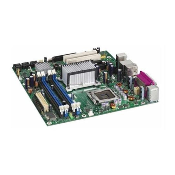
Intel DG965OT - Desktop Board Motherboard Manuals
Manuals and User Guides for Intel DG965OT - Desktop Board Motherboard. We have
2
Intel DG965OT - Desktop Board Motherboard manuals available for free PDF download: Specification, Product Manual
Intel DG965OT - Desktop Board Motherboard Specification (96 pages)
Product Specification
Brand:
Intel
| Category:
Motherboard
| Size: 2.36 MB
Table of Contents
Revision History
2
Intended Audience
3
What this Document Contains
3
Table of Contents
5
Tables
10
1 Product Description
10
Contents
10
Overview
10
Feature Summary
10
Manufacturing Options
11
Product Description
11
Board Layout
12
Figures
12
Major Board Components
12
Board Components Shown in Figure 1
13
Block Diagram
14
Online Support
15
Processor
15
Supported Memory Configurations
16
Memory Configurations
17
System Memory
16
Memory Operating Frequencies
17
Memory Channel and DIMM Configuration
18
Dual Channel (Interleaved) Mode Configuration with Three Dimms
19
Dual Channel (Interleaved) Mode Configuration with Two Dimms
19
Dual Channel (Interleaved) Mode Configuration with Four Dimms
20
Single Channel (Asymmetric) Mode Configuration with One DIMM
21
Single Channel (Asymmetric) Mode Configuration with Three Dimms
21
Flex Mode Configuration with Two Dimms
22
Intel G965 Express Chipset
23
Intel ® G965 Express Chipset
23
Intel G965 Graphics Subsystem
23
Configuration Modes
25
Usb
26
Serial ATA Interfaces
26
Serial Ata Support
26
Parallel IDE Interface
27
Real-Time Clock, CMOS SRAM, and Battery
28
Legacy I/O Controller
28
Serial Port
28
Parallel Port
28
Diskette Drive Controller
29
Keyboard and Mouse Interface (Optional)
29
Audio Jack Retasking Support
30
Audio Subsystem Software
31
Audio Connectors and Headers
31
Audio Subsystem
30
Front/Back Panel Audio Connector Options
31
LAN Subsystem
32
Intel ® 82566DC Gigabit Ethernet Controller
32
LAN Subsystem Software
33
RJ-45 LAN Connector with Integrated Leds
33
LAN Connector LED Locations
33
LAN Connector LED States
33
Hardware Management Subsystem
34
Hardware Monitoring and Fan Control
34
Fan Monitoring
34
Chassis Intrusion and Detection
34
Thermal Monitoring
35
Thermal Sensors and Fan Headers
35
1.10 Power Management
36
Acpi
36
Effects of Pressing the Power Switch
36
Power States and Targeted System Power
37
Hardware Support
38
Wake-Up Devices and Events
38
Power Connector
39
Fan Headers
39
Lan Wake Capabilities
40
Instantly Available Pc Technology
40
Resume on Ring
41
Wake from Usb
41
Location of the Standby Power Indicator LED
42
What this Chapter Contains
43
What this Chapter Contains
43
Detailed System Memory Address Map
44
DMA Channels
45
System Memory Map
45
Fixed I/O Map
46
I/O Map
46
PCI Configuration Space Map
47
Interrupts
48
DMA Channels
49
PCI Interrupt Routing Map
49
Connectors and Headers
50
PCI Interrupt Routing Map
50
Back Panel Connectors
51
Component-Side Connectors and Headers
52
Component-Side Connectors and Headers Shown in Figure 16
53
HD Audio Link Header
54
Front Panel Audio Header
54
Serial ATA Connectors
54
Serial Port Header
54
Chassis Intrusion Header
55
Front and Rear Chassis Fan Headers
55
Processor Fan Header
55
Processor Core Power Connector
56
Main Power Connector
56
Power Supply Connectors
56
Connection Diagram for Front Panel Header
57
Front Panel Header
57
States for a One-Color Power LED
58
States for a Two-Color Power LED
58
Connection Diagram for Front Panel USB Headers
59
Connection Diagram for IEEE 1394A Header
59
Jumper Block
60
Location of the Jumper Block
60
BIOS Setup Configuration Jumper Settings
60
2.10 Mechanical Considerations
61
Form Factor
61
Board Dimensions
61
I/O Shield
62
I/O Shield Dimensions for Boards with PS/2 Ports
62
I/O Shield Dimensions for Boards Without PS/2 Ports
63
2.11 Electrical Considerations
64
DC Loading
64
Fan Header Current Capability
64
DC Loading Characteristics
64
Add-In Board Considerations
65
Power Supply Considerations
65
2.12 Thermal Considerations
66
Localized High Temperature Zones
67
2.13 Reliability
68
Thermal Considerations for Components
68
2.14 Environmental
69
Desktop Board DG965OT Environmental Specifications
69
Technical Reference
43
Memory Map
43
Addressable Memory
43
What this Chapter Contains
71
Overview of BIOS Features
71
Introduction
71
BIOS Flash Memory Organization
72
Resource Configuration
72
PCI Autoconfiguration
72
BIOS Setup Program Menu Bar
72
BIOS Setup Program Function Keys
72
PCI IDE Support
73
System Management BIOS (SMBIOS)
73
Legacy USB Support
74
BIOS Updates
74
Language Support
75
Custom Splash Screen
75
BIOS Recovery
75
Acceptable Drives/Media Types for BIOS Recovery
75
Boot Options
76
CD-ROM Boot
76
Network Boot
76
Booting Without Attached Devices
76
Changing the Default Boot Device During POST
76
Boot Device Menu Options
76
Adjusting Boot Speed
77
Peripheral Selection and Configuration
77
BIOS Boot Optimizations
77
3.10 BIOS Security Features
78
Supervisor and User Password Functions
78
Error Messages and Beep Codes
79
Speaker
79
BIOS Beep Codes
79
Speaker ......................................................................................... 79 4.2 BIOS Beep Codes
79
BIOS Error Messages
79
Beep Codes
79
4.4 Port 80H POST Codes
80
Port 80H POST Code Ranges
80
Port 80H POST Codes
81
Typical Port 80H POST Sequence
84
Regulatory Compliance and Battery Disposal Information
85
Regulatory Compliance
85
Safety Regulations
85
European Union Declaration of Conformity Statement
86
Product Ecology Statements
88
Lead-Free Board Markings
90
EMC Regulations
91
Product Certification Markings (Board Level)
92
Product Certification Markings
92
Battery Disposal Information
93
Advertisement
Intel DG965OT - Desktop Board Motherboard Product Manual (82 pages)
Product Guide
Brand:
Intel
| Category:
Motherboard
| Size: 5.94 MB
Table of Contents
Canadian Department of Communications Compliance Statement
2
Fcc Declaration of Conformity
2
Revision History
2
Intended Audience
3
Use Only for Intended Applications
3
Box Contents
4
Table of Contents
5
Desktop Board Features
9
Supported Operating Systems
10
Tables
11
Desktop Board Components
11
Desktop Board DG965OT Components
11
Figures
11
Related Links
12
Main Memory
13
Processor
13
Intel G965 Express Chipset
14
Intel G965 Graphics Subsystem
15
Onboard Audio Subsystem
16
Input/Output (I/O) Controller
17
LAN Subsystem
17
LAN Subsystem Software
17
RJ-45 LAN Connector Leds
17
Enhanced IDE Interface
18
Hi-Speed USB 2.0 Support
18
LAN Connector LED States
18
Expandability
19
Bios
19
Serial ATA and IDE Auto Configuration
19
PCI and PCI Express* Auto Configuration
19
Security Passwords
19
Hardware Management Features
20
Hardware Monitoring and Fan Speed Control
20
Chassis Intrusion Detection
20
Power Management Features
21
Acpi
21
Power Connectors
21
Fan Headers
21
LAN Wake Capabilities
22
Instantly Available PC Technology
22
+5 V Standby Power Indicator LED
23
Resume on Ring
23
Location of Standby Power Indicator
23
Wake from USB
24
Wake from PS/2 Keyboard/Mouse
24
PME# Signal Wake-Up Support
24
WAKE# Signal Wake-Up Support
24
Speaker
24
Battery
24
Real-Time Clock
24
Serial ATA
18
Installing and Replacing Desktop Board Components
25
Before You Begin
25
Installation Precautions
26
Prevent Power Supply Overload
26
Observe Safety and Regulatory Requirements
26
Installing the I/O Shield
27
Installing and Removing the Desktop Board
28
Desktop Board DG965OT Mounting Screw Hole Locations
28
Installing and Removing a Processor
29
Installing a Processor
29
Lift Socket Lever
29
Lift the Load Plate
29
Remove the Protective Socket Cover
30
Remove the Processor from the Protective Processor Cover
30
Install the Processor
31
Close the Load Plate
31
Installing the Processor Fan Heat Sink
32
Connecting the Processor Fan Heat Sink Cable
32
Connecting the Processor Fan Heat Sink Cable to the Processor Fan Header
32
Removing the Processor
33
Installing and Removing Memory
33
Guidelines for Dual Channel Memory Configuration
33
Two or Four Dimms
33
Dual Channel Memory Configuration Example 1
33
Three Dimms
34
Dual Channel Memory Configuration Example 2
34
Dual Channel Memory Configuration Example 3
34
Installing Dimms
35
Use DDR2 Dimms
35
Installing a DIMM
36
Removing Dimms
37
Installing and Removing a PCI Express X16 Card
38
Installing a PCI Express X16 Card
38
Removing the PCI Express X16 Card
39
Removing a PCI Express X16 Card
39
Connecting the IDE Cable
40
Connecting the Serial ATA (SATA) Cable
41
Connecting the Serial ATA Cable
41
Connecting to Internal Headers
42
Internal Headers
42
Installing a Front Panel Audio Solution for Intel ® High Definition Audio
43
Front Panel Audio Header Signal Names for Intel High Definition Audio
43
AC '97 Audio Header Signal Names
43
Connecting to the USB 2.0 Headers
44
Connecting to the Front Panel Header
44
Front Panel Header
44
USB 2.0 Header Signal Names
44
Connecting to the Alternate Front Panel Power LED Header
45
Connecting to the IEEE 1394A Header
45
Connecting to the Serial Port Header
45
Alternate Front Panel Power LED Header
45
IEEE 1394A Header Signal Names
45
Serial Port Header Signal Names
45
Connecting to the HD Audio Link Header
46
Connecting to the Flexible Audio System
46
Back Panel Audio Connectors
46
HD Audio Link Header Signal Names
46
Connecting Chassis Fan and Power Cables
47
Connecting Chassis Fan Cables
47
Location of Chassis Fan Headers
47
Connecting Power Cables
48
Connecting Power Supply Cables
48
Other Connectors and Headers
49
Location of Other Connectors and Headers
49
Setting the BIOS Configuration Jumper
50
Location of the BIOS Configuration Jumper Block
50
Clearing Passwords
51
Jumper Settings for the BIOS Setup Program Modes
51
Back Panel Connectors
52
Replacing the Battery
53
Removing the Battery
57
Updating the BIOS
59
Updating the BIOS with the Intel Express BIOS Update Utility
59
Updating the BIOS with the ISO Image BIOS Update File or the Iflash Memory Update Utility
60
Obtaining the BIOS Update File
60
Updating the BIOS with the ISO Image BIOS Update File
60
Updating the BIOS with Iflash
61
Recovering the BIOS
62
Configuring for RAID (Intel Matrix Storage Technology)
63
Configuring the BIOS for Intel Matrix Storage Technology
63
SATA Port Mapping
63
Creating Your RAID Set
64
SATA Port Mapping for Desktop Board DG965OT after RAID Is Enabled
64
Loading the Intel Matrix Storage Technology RAID Drivers and Software
65
Setting up a "RAID Ready" System
65
Intel Quick Resume Technology Driver (Intel QRTD)
67
Overview
67
Intel Quick Resume Technology Power Modes
67
Installation and Configuration
68
A Error Messages and Indicators
71
BIOS Beep Codes
71
BIOS Error Messages
71
Beep Codes
71
B Regulatory Compliance
73
Safety Regulations
73
Place Battery Marking
73
European Union Declaration of Conformity Statement
74
Product Ecology Statements
75
Lead-Free Desktop Board
78
EMC Regulations
79
Ensure Electromagnetic Compatibility (EMC) Compliance
80
Product Certifications
81
Board-Level Certification Markings
81
Product Certification Markings
81
Chassis and Component Certifications
82
Advertisement
Related Products
Intel DG965MQ
Intel DG965MS
Intel DG965PZ
Intel DG965RY
Intel DG965SS
Intel DG965WH
Intel DG945GCLF
Intel DG33FBC
Intel DG41KR
Intel DG43RK
Intel Categories
Motherboard
Computer Hardware
Server
Server Board
Desktop
More Intel Manuals
Login
Sign In
OR
Sign in with Facebook
Sign in with Google
Upload manual
Upload from disk
Upload from URL