Sign In
Upload
Manuals
Brands
Endress+Hauser Manuals
Measuring Instruments
Proline Promag H 500
Endress+Hauser Proline Promag H 500 Meter Manuals
Manuals and User Guides for Endress+Hauser Proline Promag H 500 Meter. We have
2
Endress+Hauser Proline Promag H 500 Meter manuals available for free PDF download: Operating Instructions Manual, Technical Information
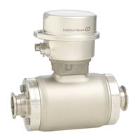
Endress+Hauser Proline Promag H 500 Operating Instructions Manual (240 pages)
Electromagnetic flowmeter
Brand:
Endress+Hauser
| Category:
Measuring Instruments
| Size: 8.63 MB
Table of Contents
Table of Contents
3
1 About this Document
6
Document Function
6
Symbols Used
6
Safety Symbols
6
Electrical Symbols
6
Communication Symbols
6
Tool Symbols
7
Symbols for Certain Types of Information
7
Symbols in Graphics
7
Documentation
8
Standard Documentation
8
Supplementary Device-Dependent Documentation
8
Registered Trademarks
8
2 Basic Safety Instructions
9
Requirements for the Personnel
9
Designated Use
9
Workplace Safety
10
Operational Safety
10
Product Safety
10
IT Security
11
Device-Specific IT Security
11
Protecting Access Via Hardware Write Protection
11
Protecting Access Via a Password
11
Access Via Web Server
12
Access Via Service Interface (CDI-RJ45)
13
3 Product Description
14
Product Design
14
Proline 500 - Digital
14
Proline 500
14
4 Incoming Acceptance and Product
16
Identification
16
Incoming Acceptance
16
Product Identification
16
Transmitter Nameplate
17
Sensor Nameplate
19
Symbols on Measuring Device
20
5 Storage and Transport
21
Storage Conditions
21
Transporting the Product
21
Measuring Devices Without Lifting
21
Measuring Devices with Lifting Lugs
22
Transporting with a Fork Lift
22
Packaging Disposal
22
6 Installation
23
Installation Conditions
23
Mounting Position
23
Environment- and Process-Related Requirements
25
Special Mounting Instructions
27
Mounting the Measuring Device
27
Required Tools
27
Preparing the Measuring Device
28
Mounting the Sensor
28
Mounting the Transmitter Housing: Proline 500 - Digital
30
Mounting the Transmitter Housing: Proline 500
32
Turning the Transmitter Housing: Proline 500
33
Turning the Display Module: Proline 500
33
Post-Installation Check
34
7 Electrical Connection
35
Connection Conditions
35
Required Tools
35
Requirements for Connecting Cable
35
Terminal Assignment
39
Shielding and Grounding
40
Preparing the Measuring Device
41
Preparing the Connecting Cable: Proline 500 - Digital
42
Preparing the Connecting Cable: Proline 500
42
Connecting the Measuring Device: Proline 500 - Digital
44
Connecting the Connecting Cable
44
Connecting the Signal Cable and the Supply Voltage Cable
49
Connecting the Measuring Device: Proline 500
51
Connecting the Connecting Cable
51
Ensuring Potential Equalization
53
Requirements
53
Connection Example, Standard Scenario
54
Connection Example in Special Situations
54
Special Connection Instructions
55
Connection Examples
55
Hardware Settings
58
Setting the Device Address
58
Enabling the Terminating Resistor
60
Activating the Default IP Address
61
Ensuring the Degree of Protection
63
Post-Connection Check
63
8 Operation Options
64
Overview of Operation Options
64
Structure and Function of the Operating
65
Structure of the Operating Menu
65
Operating Philosophy
66
Access to the Operating Menu Via the Local Display
67
Operational Display
67
Navigation View
69
Editing View
71
Operating Elements
73
Opening the Context Menu
73
Navigating and Selecting from List
75
Calling the Parameter Directly
75
Calling up Help Text
76
Changing the Parameters
76
User Roles and Related Access Authorization
77
Disabling Write Protection Via Access
77
Code
77
Enabling and Disabling the Keypad
78
Access to the Operating Menu Via the Web Browser
78
Function Range
78
Lock
78
Prerequisites
79
Establishing a Connection
80
Logging on
82
User Interface
83
Disabling the Web Server
84
Logging out
84
Access to the Operating Menu Via the Operating Tool
85
Connecting the Operating Tool
85
Fieldcare
88
Devicecare
89
9 System Integration
91
Overview of Device Description Files
91
Current Version Data for the Device
91
Operating Tools
91
Device Master File (GSD)
91
Manufacturer-Specific GSD
92
Profile GSD
92
Compatibility with Earlier Model
92
Automatic Identification
92
Setting)
92
Manual Setting
93
Replacing the Measuring Devices Without Changing the GSD File or Restarting the Controller
93
Using the GSD Modules of the Previous Model
94
Using the CONTROL_BLOCK Module
94
In the Previous Model
94
Cyclic Data Transmission
96
Block Model
96
Description of the Modules
96
Address Shifting Configuration
102
Function Description
102
Structure
102
Configuring Address Shifting
103
Accessing Data Via PROFIBUS DP
103
10 Commissioning
105
Function Check
105
Switching on the Measuring Device
105
Connecting Via Fieldcare
105
Configuring the Device Address Via Software
105
PROFIBUS Network
105
Setting the Operating Language
105
Configuring the Measuring Device
106
Defining the Tag Name
107
Setting the System Units
108
Interface
109
Configuring the Analog Inputs
111
Displaying the I/O Configuration
111
Configuring the Current Input
112
Configuring the Status Input
113
Configuring the Current Output
114
Configuring the Pulse/Frequency
117
Switch Output
117
10.6.10 Configuring the Relay Output
123
10.6.11 Configuring the Local Display
125
10.6.12 Configuring the Low Flow Cut off
127
10.6.13 Configuring Empty Pipe Detection
129
Advanced Settings
130
Carrying out a Sensor Adjustment
131
Configuring the Totalizer
131
Carrying out Additional Display Configurations
133
Performing Electrode Cleaning
136
WLAN Configuration
137
Configuration Management
138
Using Parameters for Device Administration
140
Simulation
141
Protecting Settings from Unauthorized
144
Access
144
Write Protection Via Access Code
144
Write Protection Via Write Protection
146
Switch
146
11 Operation
148
Reading the Device Locking Status
148
Adjusting the Operating Language
148
Configuring the Display
148
Reading Measured Values
148
Process Variables" Submenu
149
Totalizer
150
Input Values" Submenu
151
Output Values
152
Adapting the Measuring Device to the Process
154
Conditions
154
Performing a Totalizer Reset
154
Showing Data Logging
155
12 Diagnostics and Troubleshooting
158
General Troubleshooting
158
Diagnostic Information Via Light Emitting
161
Diodes
161
Transmitter
161
Sensor Connection Housing
162
Diagnostic Information on Local Display
164
Diagnostic Message
164
Calling up Remedial Measures
166
Diagnostic Information in the Web Browser
166
Diagnostic Options
166
Calling up Remedy Information
167
Diagnostic Information in Fieldcare or Devicecare
167
Diagnostic Options
167
Calling up Remedy Information
168
Adapting the Diagnostic Information
169
Adapting the Diagnostic Behavior
169
Overview of Diagnostic Information
172
Diagnostic of Sensor
172
Diagnostic of Electronic
174
Diagnostic of Configuration
182
Diagnostic of Process
191
Pending Diagnostic Events
194
Diagnostic List
195
12.10 Event Logbook
195
12.10.1 Reading out the Event Logbook
195
12.10.2 Filtering the Event Logbook
196
12.10.3 Overview of Information Events
196
12.11 Resetting the Measuring Device
198
12.11.1 Function Scope of the "Device Reset" Parameter
198
12.12 Device Information
198
12.13 Firmware History
200
13 Maintenance
201
Maintenance Tasks
201
Exterior Cleaning
201
Interior Cleaning
201
Replacing Seals
201
Measuring and Test Equipment
201
Endress+Hauser Services
201
14 Repairs
202
General Notes
202
Repair and Conversion Concept
202
Notes for Repair and Conversion
202
Spare Parts
202
Endress+Hauser Services
202
Return
202
Disposal
203
Removing the Measuring Device
203
Disposing of the Measuring Device
203
15 Accessories
204
Device-Specific Accessories
204
For the Transmitter
204
For the Sensor
205
Service-Specific Accessories
206
System Components
206
16 Technical Data
207
Application
207
Function and System Design
207
Input
207
Output
211
Power Supply
215
Performance Characteristics
216
Installation
217
Environment
217
Process
219
16.10 Mechanical Construction
221
16.11 Operability
225
16.12 Certificates and Approvals
229
16.13 Application Packages
231
16.14 Accessories
232
16.15 Supplementary Documentation
232
Index
234
Advertisement
Endress+Hauser Proline Promag H 500 Technical Information (126 pages)
Electromagnetic flowmeter
Brand:
Endress+Hauser
| Category:
Measuring Instruments
| Size: 10.36 MB
Table of Contents
Table of Contents
2
About this Document
4
Symbols Used
4
Function and System Design
5
Measuring Principle
5
Measuring System
6
Equipment Architecture
8
Safety
8
Input
10
Measured Variable
10
Measuring Range
10
Operable Flow Range
11
Input Signal
12
Output
13
Output and Input Variants
13
Output Signal
14
Signal on Alarm
17
Ex Connection Data
20
Low Flow Cut off
21
Galvanic Isolation
21
Protocol-Specific Data
21
Power Supply
26
Terminal Assignment
26
Device Plugs Available
27
Supply Voltage
27
Pin Assignment, Device Plug
28
Power Consumption
30
Current Consumption
30
Power Supply Failure
30
Electrical Connection
31
Potential Equalization
41
Terminals
43
Cable Entries
43
Cable Specification
43
Performance Characteristics
47
Reference Operating Conditions
47
Maximum Measured Error
47
Repeatability
48
Temperature Measurement Response Time
48
Influence of Ambient Temperature
48
Installation
49
Mounting Location
49
Inlet and Outlet Runs
50
Adapters
51
Length of Connecting Cable
51
Mounting the Transmitter Housing
53
Environment
54
Ambient Temperature Range
54
Storage Temperature
55
Degree of Protection
55
Vibration Resistance
55
Shock Resistance
55
Mechanical Load
55
Interior Cleaning
55
Electromagnetic Compatibility (EMC)
55
Process
56
Medium Temperature Range
56
Conductivity
56
Pressure-Temperature Ratings
56
Proline Promag H
56
Pressure Tightness
62
Flow Limit
62
Pressure Loss
62
System Pressure
63
Vibrations
64
Mechanical Construction
64
Dimensions in si Units
64
Dimensions in US Units
83
Weight
98
Measuring Tube Specification
99
Materials
99
Fitted Electrodes
101
Process Connections
102
Surface Roughness
102
Operability
102
Operating Concept
102
Languages
102
Local Operation
103
Remote Operation
103
Service Interface
109
Network Integration
110
Supported Operating Tools
111
Historom Data Management
112
Certificates and Approvals
114
CE Mark
114
C-Tick Symbol
114
Ex Approval
114
Sanitary Compatibility
117
Pharmaceutical Compatibility
117
Functional Safety
117
HART Certification
117
FOUNDATION Fieldbus Certification
117
Certification PROFIBUS
118
Ethernet/Ip Certification
118
Certification PROFINET
118
Radio Approval
118
Pressure Equipment Directive
118
Measuring Instrument Approval
118
Additional Certification
118
Other Standards and Guidelines
118
Application Packages
119
Diagnostics Functions
119
Heartbeat Technology
120
Cleaning
120
OPC-UA Server
120
Ordering Information
119
Accessories
120
Proline Promag H
120
Device-Specific Accessories
121
Communication-Specific Accessories
122
Service-Specific Accessories
123
System Components
124
Supplementary Documentation
124
Standard Documentation
124
Device-Dependent Additional Documentation
124
Registered Trademarks
125
Advertisement
Related Products
Endress+Hauser Proline Promag H 200
Endress+Hauser Proline Promag H 100 EtherNet/IP
Endress+Hauser Proline Promag H 300
Endress+Hauser HART Proline Promass 83
Endress+Hauser HART Proline Promag 51
Endress+Hauser HART Proline Promass 80
Endress+Hauser HART
Endress+Hauser Analytikjena SELECT Head 8/250 ml
Endress+Hauser Analytikjena SELECT Head 8/50 ml
Endress+Hauser PROline promag 50 w
Endress+Hauser Categories
Measuring Instruments
Transmitter
Radar
Switch
Accessories
More Endress+Hauser Manuals
Login
Sign In
OR
Sign in with Facebook
Sign in with Google
Upload manual
Upload from disk
Upload from URL