Sign In
Upload
Manuals
Brands
Endress+Hauser Manuals
Measuring Instruments
Proline Promag 300
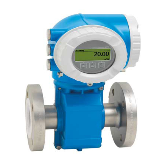
Endress+Hauser Proline Promag 300 Manuals
Manuals and User Guides for Endress+Hauser Proline Promag 300. We have
3
Endress+Hauser Proline Promag 300 manuals available for free PDF download: Description Of Device Parameters, Special Documentation, Safety Instructions
Endress+Hauser Proline Promag 300 Description Of Device Parameters (273 pages)
Modbus RS485 Electromagnetic flowmeter
Brand:
Endress+Hauser
| Category:
Measuring Instruments
| Size: 2.52 MB
Table of Contents
Table of Contents
3
1 About this Document
4
Document Function
4
Target Group
4
Information on the Document Structure
4
Using this Document
4
Structure of a Parameter Description
6
Symbols Used
6
Symbols for Certain Types of Information
6
Symbols in Graphics
7
Operating Instructions
7
Supplementary Device-Dependent Documentation
7
Standard Documentation
7
Overview of the Expert Operating Menu
8
3 Description of Device Parameters
11
Locking Status
12
User Interface
12
Access Status
13
Ent. Access Code
13
"Display" Submenu
14
"System" Submenu
14
Display Language
15
Format Display
16
0% Bargraph 1 (0123)
18
Value 1 Display
18
100% Bargraph 1
19
Decimal Places 1 (0095)
19
Value 2 Display
20
Decimal Places 2 (0117)
21
Value 3 Display
21
0% Bargraph 3 (0124)
22
100% Bargraph 3
22
Decimal Places 3 (0118)
23
Value 4 Display
23
Additional Information
24
Decimal Places 4
24
Display Interval
24
Display Damping
25
Header
26
Header Text
26
Separator
27
Backlight
28
Configuration Backup" Submenu
28
Operating Time
28
Config. Managem.
29
Last Backup
29
Backup State
30
Compar. Result
30
"Diagn. Handling" Submenu
31
Alarm Delay
31
"Diagn. Behavior" Submenu
32
Diagnostic No. 043 (Sens.short Circ.)
33
Diagnostic No. 302 (Verific. Active)
33
Diagnostic No. 376 (Sensor Electron.)
34
Diagnostic No. 377 (Sensor Electron.)
34
Diagnostic No. 441 (Curr.output 1 to N)
34
Diagnostic No. 442 (Freq. Output 1 to N)
35
Diagnostic No. 443 (Pulse Output 1 to N)
35
Diagnostic No. 444 (Current Input 1 to N)
35
Diagnostic No. 531 (Empty Pipe Det.)
36
Diagnostic No. 543 (Double Pulse Out)
36
Diagnostic No. 832 (Electronic Temp.)
37
Diagnostic No. 833 (Electronic Temp.)
37
Diagnostic No. 834 (Process Temp.)
37
Diagnostic No. 835 (Process Temp.)
38
Diagnostic No. 937 (EMC Interference)
38
Diagnostic No. 938 (EMC Interference)
38
Administration" Submenu
39
Diagnostic No. 961
39
Diagnostic No. 962 (Pipe Empty)
39
"Def. Access Code" Wizard
40
Confirm Code
41
Reset Acc. Code
41
Activate SW Opt.
42
Device Reset
42
SW Option Overv.
43
Sensor" Submenu
44
Measured Val." Submenu
44
Volume Flow
45
Mass Flow
45
Correct.vol.flow
46
Flow Velocity
46
Conductivity
46
Corrconductivity
47
Temperature
47
Density
47
Totalizer Val. 1 to N
48
Tot. Overflow 1 to N
48
Measured Val. 1 to N
50
Measur. Curr. 1 to N
50
Val.stat.inp.
50
Output Curr. 1 to N
51
Output Freq. 1 to N
52
Switch Status 1 to N
53
Switch Status
54
Switch Cycles
54
Max. Cycles No.
54
Pulse Output
55
Volume Flow Unit
55
System Units" Submenu
55
Volume Unit
57
Conductiv. Unit
57
Temperature Unit
58
Mass Flow Unit
58
Mass Unit
59
Density Unit
60
Cor.volflow Unit
60
Corr. Vol. Unit
61
Date/Time Format
62
Volume Text
63
Volume Offset
64
Volume Factor
64
Mass Text
64
Mass Offset
65
Mass Factor
65
Corr. Vol. Text
65
Corr Vol. Offset
66
Cor.vol. Factor
66
Density Text
66
Density Offset
67
Density Factor
67
Spec. Enth. Text
67
Spec. Enth. Off.
68
Spec. Enth. Fac. (0583)
68
Energy Text (0600)
68
Energy Offset
69
Energy Factor (0586)
69
Pressure Text (0581)
69
Pressure Offset
70
Process Param." Submenu
70
Pressure Factor (0579)
70
Filter Options
71
Flow Damping
73
Flow Override
73
Conduct. Damping
74
Temp. Damping
74
Conduct. Measur.
74
Cond. Temp.coeff
75
Assign Variable
76
On Value
76
Off Value
77
Pres. Shock Sup.
77
Empty Pipe Det.
79
Switch Point EPD
79
Response Time
80
New Adjustment
80
Progress
80
Empty Pipe Value
81
Full Pipe Value
81
Meas. Value EPD
81
Ecc
82
ECC Recov. Time
82
ECC Clean. Cycle
83
ECC Polarity
83
External Comp." Submenu
83
Temp. Source
84
External Temp.
84
Density Source
85
External Density
85
Fixed Density
85
Ref. Temperature
86
Ref. Density
86
Linear Exp Coeff
88
Square Exp Coeff
88
Sensor Adjustment" Submenu
88
Install. Direct.
89
Integration Time
89
Measuring Period
89
Vol. Flow Offset
90
Vol. Flow Factor
90
Mass Flow Offset
91
Mass Flow Factor
91
Conduct. Offset
91
Conduct. Factor
92
Corr. Vol Offset
92
Corr. Vol Factor
92
Temp. Offset
93
Temp. Factor
93
Corr.cond.offset
94
Corr.cond.factor
94
Flow Vel. Offset
94
Flow Vel. Factor
95
Nominal Diameter
95
Calibration" Submenu
95
Cal. Factor
96
Zero Point
96
Cond. Cal. Fact.
96
I/O Configuration" Submenu
96
I/O 1 to N Info
97
I/O 1 to N Terminals
97
Alteration Code
98
Apply I/O Config
98
I/O 1 to N Type
98
Input" Submenu
99
Current Input 1 to N" Submenu
99
Signal Mode
100
Current Span
100
0/4 Ma Value
100
Expert → Input
100
20 Ma Value
101
Failure Mode
101
Failure Value
102
Status Input 1 to N" Submenu
102
Status Input 1 to N
102
Expert → Input → Current Input 1 to N
102
Terminal No. (1611-1 to N)
102
User Interface
102
Not Used
102
Additional Information
102
Not Used" Option
102
Assign Stat.inp.
103
Active Level
104
Terminal No.
99
Output" Submenu
104
Current Output 1 to N" Submenu
104
The Current Input Module Does Not Use any Terminal Numbers
105
Assign Curr. 1 to N
106
Measuring Mode
110
Damping Out. 1 to N
114
Failure Current
117
Pulse/Frequency/Switch Output
118
Assign Pulse 1 to N
122
Value Per Pulse
122
Pulse Width
123
Pulse Output 1 to N
125
Assign Freq.
126
Min. Freq. Value
126
Max. Freq. Value
127
Val. at Min.freq
127
Val. at Max.freq
128
Failure Freq.
131
Switch out Funct
132
Assign Diag. Beh
132
Assign Limit
133
Switch-On Value
135
Switch-Off Value
135
Assign Dir.check
136
Assign Status
136
Switch-On Delay
136
Switch-Off Delay
137
Invert Outp.sig.
138
Relay Output 1 to N" Submenu
138
Relay Outp.func.
139
Assign Limit
140
Assign Diag. Beh
141
Assign Status
141
Switch-Off Value
142
Switch-Off Delay
142
Switch-On Value
142
Switch-On Delay
143
Failure Mode
143
Switch Status
144
Powerless Relay
144
"Double Pulse Output" Submenu
145
Master Term. No.
145
Slave Term. No.
145
Communication" Submenu
149
Bus Address
150
Modbus Config." Submenu
150
Baudrate
151
Data Trans. Mode
151
Parity
151
Byte Order
152
Telegram Delay
153
Bus Termination
154
Device ID
155
Device Revision
155
Modbus Info" Submenu
155
Modbus Data Map" Submenu
156
Scan List Reg.0 to 15
156
Web Server" Submenu
156
DHCP Client
157
MAC Address
157
Webserv.language
157
Default Gateway
158
IP Address
158
Subnet Mask
158
Login Page
159
Webserver Funct.
159
WLAN Settings" Submenu
159
Wlan
160
Network Security
161
SSID Name
161
WLAN Mode
161
Sec. Identific.
162
User Name
162
WLAN IP Address
162
WLAN Password
162
WLAN MAC Address
163
WLAN Passphrase
163
WLAN Subnet Mask
163
Assign SSID Name
164
WLAN Channel
164
Connection State
165
Gateway IP Addr.
165
Rec.sig.strength
165
Select Antenna
165
IP Address DNS
166
Reset All Tot.
166
Application" Submenu
166
"Totalizer 1 to N" Submenu
167
Unit Totalizer 1 to N
168
Control Tot. 1 to N
169
Operation Mode
169
Preset Value 1 to N
170
Custody Transfer" Submenu
171
Diagnostics" Submenu
171
Actual Diagnos.
172
Prev.diagnostics
173
Timestamp
173
Diagnostic List" Submenu
174
Time Fr. Restart
174
Diagnostics 1
175
Event Logbook" Submenu
179
Event List
180
Custody Transfer Logbook" Submenu
181
Device Information" Submenu
181
Device Tag
182
Firmware Version
182
Serial Number
182
Device Name
183
Ext. Order CD. 1
183
Order Code
183
ENP Version
184
Ext. Order CD. 2
184
Ext. Order CD. 3
184
Bootloader Rev.
185
Build No. Softw.
185
Mainboard Module" Submenu
185
Software Rev.
185
Sens. Electronic" Submenu
186
I/O 1 Terminals
187
I/O Module 1" Submenu
187
I/O Module 2" Submenu
187
I/O Module 3" Submenu
189
Display Module" Submenu
190
Data Logging" Submenu
191
Assign Chan. 1
192
Assign Chan. 2
192
Assign Chan. 3
193
Assign Chan. 4
193
Clear Logging
194
Data Logging
194
Data Log.control
195
Logging Delay
195
Data Log. Status
196
Logging Duration
196
Display Channel 1
197
Display Channel 2
197
Display Channel 3
198
Display Channel 4
198
Minimum Value
199
Reset Min/Max
199
Maximum Value
200
Heartbeat" Submenu
201
Simulation" Submenu
201
Assign Proc.var.
202
Proc. Var. Value
203
Status Inp. Sim.
203
Curr.inp 1 to N Sim.
204
Signal Level
204
Curr.out. 1 to N Sim.
205
Value Curr.inp 1 to N
205
Value Curr.out 1 to N
205
Freq Value 1 to N
206
Freqoutputsim 1 to N
206
Puls.outp.sim. 1 to N
207
Pulse Value 1 to N
207
Diag. Event Sim.
211
Event Category
211
4 Country-Specific Factory Settings
212
SI Units
212
System Units
212
Full Scale Values
212
Output Current Span
213
Pulse Value
213
On Value Low Flow Cut off
213
US Units
214
System Units
214
Full Scale Values
214
Output Current Span
215
Pulse Value
215
On Value Low Flow Cut off
216
5 Explanation of Abbreviated Units
217
SI Units
217
US Units
217
Imperial Units
218
Modbus RS485 Register Information
219
Structure of the Register Information
219
Notes
219
Address Model
219
Overview of the Expert Operating Menu
220
Register Information
232
System" Submenu
233
Sensor" Submenu
237
I/O Config." Submenu
246
Input" Submenu
247
Output" Submenu
248
"Communication" Submenu
253
"Modbus Data Map" Submenu
254
"Web Server" Submenu
254
Application" Submenu
255
Diagnostics" Submenu
257
Index
262
Advertisement
Endress+Hauser Proline Promag 300 Special Documentation (52 pages)
Brand:
Endress+Hauser
| Category:
Industrial Equipment
| Size: 1.63 MB
Table of Contents
Table of Contents
3
Manufacturer's Declaration
4
Safety-Related Characteristic Values
5
Certificate
8
About this Document
9
Document Function
9
Using this Document
9
Symbols
9
Supplementary Device Documentation
10
Design
11
Permitted Device Types
11
Marking
13
Notes on the Redundant Use of Multiple
14
Sensors
14
Basic Conditions for Use in Safety-Related Applications
16
Safety Measured Error
17
Useful Lifetime of Electrical
19
Components
19
Commissioning
19
And Configuration)
19
Requirements for the Personnel
19
Installation
19
Operation
20
Parameter Configuration for Safety
20
Related Applications
20
Operation
29
Device Behavior During Power-Up
29
Device Behavior in Safety Function
29
Demand Mode
29
Safe States
29
Device Behavior in Event of Alarms and Warnings
29
Alarm and Warning Messages
30
Proof Testing
30
Test Sequence a (PTC = 99 %)
32
Test Sequence C (PTC = 98 %)
35
Test Sequence D (PTC = 36 %)
36
Test Sequence E (PTC = 19 %)
40
Test Sequence F (PTC = 0 %)
41
Verification Criterion
43
Repair and Error Handling
43
Maintenance
43
Repair
43
Modification
44
Taking out of Service
44
Disposal
44
Appendix
44
Structure of the Measuring System
44
Commissioning or Proof Test Report
47
Verification or Calibration
49
Version History
49
Endress+Hauser Proline Promag 300 Safety Instructions (20 pages)
Brand:
Endress+Hauser
| Category:
Measuring Instruments
| Size: 0.34 MB
Table of Contents
Table of Contents
5
Associated Documentation
6
Manufacturer' S Certificates
6
Manufacturer Contact Address
7
Extended Order Code
7
Safety Instructions: General
10
Safety Instructions: Installation
10
Temperature Tables
11
Connection Data: Signal Circuits
15
Advertisement
Advertisement
Related Products
Endress+Hauser Proline Promass 83
Endress+Hauser Proline Promass 80
Endress+Hauser Proline Prowirl 72
Endress+Hauser Proline Promass 84
Endress+Hauser Proline Prosonic Flow P
Endress+Hauser Proline Prosonic Flow W
Endress+Hauser Proline Prowirl 73
Endress+Hauser Proline Promass series
Endress+Hauser Proline Promag 10
Endress+Hauser Proline Promass 84F
Endress+Hauser Categories
Measuring Instruments
Transmitter
Radar
Switch
Accessories
More Endress+Hauser Manuals
Login
Sign In
OR
Sign in with Facebook
Sign in with Google
Upload manual
Upload from disk
Upload from URL