Sign In
Upload
Manuals
Brands
Carrier Manuals
Air Conditioner
48/50PG C03-14
Carrier 48/50PG C03-14 Manuals
Manuals and User Guides for Carrier 48/50PG C03-14. We have
1
Carrier 48/50PG C03-14 manual available for free PDF download: Operation And Service Manual
Carrier 48/50PG C03-14 Operation And Service Manual (189 pages)
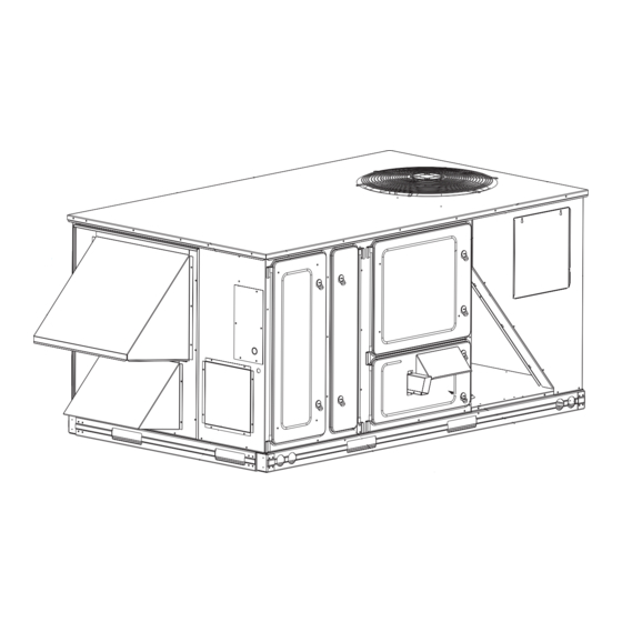
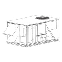
Single Package Rooftop Units With COMFORTLink Controls Version 5.x and PURON (R-410A) Refrigerant
Brand:
Carrier
| Category:
Air Conditioner
| Size: 9.71 MB
Table of Contents
Table of Contents
1
Safety Considerations
2
Comfortlink Control
3
Scrolling Marquee
3
Accessory Navigator Display
4
CCN Tables and Display
4
Operation
4
System Pilott and Touch Pilot Devices
4
Force Hierarchy
5
Generic Status Display Table
5
Scrolling Marquee Mode and Menu Display Structure
5
System Pilott User Interface
5
Compressor Rotation
6
Conventions Used in this Manual
6
Crankcase Heater(S)
6
Refrigerant Service Ports
6
Unit Preparation
6
General
3
Basic Control Usage
3
Start-Up
6
Power Supply
6
Internal Wiring
6
Evaporator Fan
6
48/50PG03−14 Size Units, Panel and Filter Locations (48PG03−07 Unit Shown)
7
48/50PM16−28 Size Units, Panel and Filter Locations (48PM24 Unit Shown)
7
Controls Quick Set−Up
8
Condenser Fans and Motors
8
Gas Heat (48PG and 48PM)
8
Control Set Point and Configuration Log
8
Return−Air Filters
8
Outdoor−Air Inlet Screens
8
Air Baffles
8
Accessory Installation
8
Orifice Change (48PG and 48PM)
8
Energyx
8
Space Temperature Sensor Control − Direct Wired
9
T−58 Communicating Room Sensor
9
System Pilot − Communication Space Sensor
9
(T−55 or T−56 or T−59)
9
CCN Linkage Control
9
Space Humidistat Control
9
Relative Humidity Sensor Control
9
CCN Communication
9
Accessories
9
Programming Operating Schedules
10
Outdoor Enthalpy
10
IAQ Switch
10
IAQ Sensor
10
Setting an Occupied Time Schedule — Weekdays Only for 7:30 to 22:30
11
Service Test
12
Independent Outputs
12
Fan Test
12
Cooling Test
12
Humidi−Mizert Test
12
Heating Test
13
Dehumidification Control
13
Remote Occupancy
13
Alarm Output
13
Third Party Control
13
Cooling/Heating Control
13
Fire Shutdown
13
Controls Operation
14
Economizer Monitoring
14
Economizer Damper Control
14
Unit Configuration
14
Display Configuration
14
Thermostat Control Type (T.CTL)
15
Fan on When Occupied (OC.FN)
15
Shut down on IDF Failure (IDF.F)
15
Fan Status Switch (FN.SW)
15
Modes
15
HVAC Operation Disabled (HV.DN)
16
General Operation
16
Temperature Setpoint Determination
16
Timed Override in Effect (T.OVR)
16
Occupancy Determination
17
Level 1 Priority
17
Level 2 Priority
17
Indoor Fan Operation
17
Cooling Operation
18
Cooling Mode Control
18
Staging Control
18
Thermostat Control
18
Compressor Control
19
Outdoor Fan Control
19
Space Sensor Control
19
Units Without Humidi−Mizert System
19
Outdoor Fan Level Transitions
20
48/50PG03−16 Fan Level Control of Fans and Contactors
20
48/50PG20−28 and PM16−28 Fan Level Control of Outdoor Fan Contactors (OFC(X))
20
Heating Operation
21
Heating Mode Control
21
Supply−Air Temperature Sensor (SAT)
21
Heat Relay Control
22
Integrated Gas Controller (IGC)
22
Economizer
23
Economizer Actuator Communications
23
Unoccupied Free Cooling
23
LCSP and HCSP Transitions for Space Temperature Mode
23
Optional Humidi−Mizert Dehumidification System
24
Dehumidification Demand
24
Reheat Modes
24
Power Exhaust
24
Control Modes with Humidi−Mizert System
25
Normal Cooling Mode — Humidi−Mizert System
25
Subcooling Mode (Reheat1) — Humidi−Mizert System
26
Hot Gas Reheat Mode (Reheat2) — Humidi−Mizer System
26
Subcooling Mode (Reheat1) — Humidi−Mizer System
27
Hot Gas Reheat Mode (Reheat2) — Humidi−Mizert System 48/50PG20−28 and 48/50PM16−28
28
Reheat Control
28
Reheat Outdoor Fan Control
28
Reheat Mode Diagnostic Help
29
Humidi−Mizert System Valve Locations
29
Air Baffles
30
Indoor Air Quality (IAQ)
30
IAQ (Analog Input)
30
Air Baffle Dimensions
31
IAQ (Switch Input)
33
Outdoor Air Quality (Analog Input)
33
IAQ Control
33
Fan Enable (Analog IAQ Sensor)
34
Fan Enable (Switch Input)
34
Energyx
34
Adaptive Fan
34
Fan Speed − Reheat2 (FS.RH)
35
Fan Speed − Heating (FS.HT)
35
Temperature Compensated Start
35
Temperature Compensated Start Logic
35
Carrier Comfort Network (CCN)R Configuration
35
Global Schedule Broadcast (BROD"B.GS)
36
CCN Broadcast Acknowledger (BROD"B.ACK)
36
Schedule Number (SCH.O"SCH.N)
36
Demand Limit
36
Linkage
36
Alarm Handling
37
Troubleshooting
37
Alarm Relay Output
37
Alarms and Alerts
37
CCN Alarm Broadcast
37
Complete Unit Stoppage
37
Restart Procedure
37
Alarms"Curr (Currently Active Alarms)
38
Alarms"Hist (Alarm History)
38
Alarms"R.hist (Reset Alarm History)
38
Diagnostic Alarm Codes and Possible Causes
38
Alert Code T075 − Supply Air Temperature Thermistor Failure
39
Alert Code T076 − Return Air Thermistor Failure
39
Alert Code T077 − Space Relative Humidity Sensor Failure
39
Alert Code T080 − Circuit C Saturated Condensing Temp Thermistor Failure
39
Alarm Code A154 − Serial EEPROM Hardware Failure
40
Alarm Code A156 − Critical Serial EEPROM Storage Fail Error
40
Alarm Code T153 − Real Time Clock Hardware Failure
40
Alarm Code T155 − Serial EEPROM Storage Failure Error
40
Comfortlinkt Alarm Codes
41
Alert Code T410
43
Alert Code T411
43
Alert Code T412 – Thermostat W2 Input Activated Without W1 Activated
43
Alert Code T413 – Thermostat y and W Inputs Activated Simultaneously
43
Fan Status Switch Off/Fan Contactor on
43
Alert Code T415-418
44
Communication Failures
44
Control Module Communication
44
Green LED
44
Red LED
44
Cooling Service Analysis
45
Cooling Troubleshooting
45
Humidi-Mizer Service Analysis
46
Humidi−Mizert Troubleshooting
46
Economizer Service Analysis
47
Economizer Troubleshooting
47
Electric Heat (50PG Units)
48
Gas Heat (48PG Units)
48
Gas Heating Service Analysis
48
Heating Troubleshooting
48
IGC Service Analysis Logic
49
Electric Heat Service Analysis
50
IGC Board LED Alarm Codes
50
Phase Loss Protection
51
Phase Reversal Protection
51
Refrigerant Temperatures
51
Thermistor Troubleshooting
51
Forcing Inputs and Outputs
52
Saturated Condensing Temperature Thermistor Location — 48/50PG03−07
52
Sensor Trim
52
Transducer Troubleshooting
52
Temperature (_F) Vs Resistance/Voltage Drop Values for OAT, SAT, and SPT Thermistors (10K at 25_C Type II Resistors)
53
Temperature (_F) Vs. Resistance/Voltage Drop Values for SCT Sensors (5K at 25_C Resistors)
54
General
55
Pressure (Psig) Vs. Voltage Drop Values for Suction Pressure Transducers
55
48PG03−16 Control Wiring Schematic
56
50PG03−16 Control Wiring Schematic
57
Typical 48/50PG03−14 Power Wiring Schematic and Legend (48/50PG08−14 Shown)
58
Typical 48PG03−16 with Humidi−Mizert System Control Wiring Schematic(48PG08−16 Shown)
59
Typical 50PG03−16 with Humidi−Mizert System Control Wiring Schematic(50PG08−16 Shown)
60
Typical 48/50PG03−14 with Humidi−Mizert System Power Wiring Schematic and Legend
61
Typical 48PM16−28 Control Schematic
62
Typical 48PM16−28 with Humidi−Mizert System Control Schematic
63
Typical 50PM16−28 Control Schematic
64
Typical 50PM16−28 with Humidi−Mizert Control Schematic
65
Typical 48/50PM16−28 Power Schematic
66
Typical 48/50PM16−28 with Humidi−Mizert System Power Schemati
67
Typical 48/50PG03−16 Unit Component Arrangement (Sizes 03−07 Shown)
68
48/50PM16−28 Component Arrangement
69
48/50PM16−28 with Humidi−Mizert Component Arrangement
70
Main Base Board (MBB)
71
MBB Connections
72
Economizer Control Board (ECB)
73
ECB Connections
74
IGC Connections
75
Integrated Gas Control (IGC) Board
75
Field Connection Terminal Strip
76
Low Voltage Terminal Strip (TB1)
76
Accessory Navigatort Display
77
Carrier Comfort Network (CCN)R Interface
77
Scrolling Marquee Display
77
CCN System Architecture
78
Energyx
78
Field-Installed Accessories
79
Space Temperature Sensor (T−55)
79
Space Temperature Sensor (T−56)
79
Space Temperature Sensor (T−58)
79
Space Temperature Sensor Averaging
80
Space Temperature Sensor Averaging with 3 T−55 Sensors and One T−56 Sensor
80
Carrier Accessory Kits
81
Indoor Air Quality
81
Outdoor Air Quality
81
Two−Position Damper
81
Cleaning
82
Coil Maintenance and Cleaning Recommendation
82
Space Humidity Sensor
82
Major System Components
55
Service
82
Condensate Drain Pan (48/50PG03−14 Units)
83
Routine Cleaning of Round−Tube Coil Surfaces
83
Condensate Drain Pan (48/50PM16−28 Units)
84
Filters
84
Lubrication
84
Main Burner (48PG and PM)
84
Condenser and Evaporator−Fan Motor Bearings
85
Economizer or Manual Outside Air Damper
85
Evaporator Fan Service and Replacement
85
Evaporator−Fan Motor Adjustment
85
Evaporator Fan Belt Tension Adjustment
86
Condenser-Fan Adjustment
87
Economizer Operation During Power Failure
87
Evacuation
87
NOVATION Heat Exchanger Condenser Service and Replacement
87
Verify Sensor Performance
87
Low Charge Cooling
88
No Charge
88
Refrigerant Charge
88
Triple Evacuation Method
88
Charging Chart — 48/50PG05
89
Charging Chart — 48/50PG06
89
Charging Chart — 48/50PG07
89
Charging Chart — 48/50PG08 and 09
89
Charging Chart — 48/50PG12
90
Charging Chart — 48/50PG14
90
Charging Chart − 48/50PM16 and 20
90
Charging Chart − 48/50PM24
90
Altitude Compensation
91
Gas Valve Adjustment (48PG and PM)
91
Puronr Refrigerant
91
Typical Gas Valve (20−28 Sizes Shown)
91
High Altitude (48PG and PM)
92
Main Burners (48PG and 48PM)
92
Natural Gas
92
Propane Gas
92
Control Circuit, 24−V
93
Diagnostic Leds
93
Energyx
93
Filter Drier
93
Protective Devices
93
Relief Devices
93
Replacement Parts
93
Appendix A - Local Display and Ccn Tables
94
Mode — Time Clock
108
Mode — Operating Modes
109
Single-Circuit Units
112
Dual Circuit Units
112
APPENDIX B − CONTROL MODES with Humidi−Mizert SYSTEM and ECONOMIZER
112
Appendix C - Start−Up Data
113
Appendix D - Additional Start−Up Data
169
Mode — Configuration
180
Control Set Point and Configuration Log
180
Indicate Unit Settings below
180
Pre-Start-Up
188
Unit Start-Up Checklist
188
Advertisement
Advertisement
Related Products
Carrier 48/50PD05
Carrier 48/50PM C16-28
Carrier MOTORMASTER 48/50P3
Carrier MOTORMASTER 48/50P2
Carrier MOTORMASTER 48/50P5030-100
Carrier MOTORMASTER 48/50P4
Carrier 48/50PG Series
Carrier 48/50PM Series
Carrier WEATHERMAKER 48/50AJ
Carrier 48/50TC04---28
Carrier Categories
Air Conditioner
Heat Pump
Furnace
Thermostat
Chiller
More Carrier Manuals
Login
Sign In
OR
Sign in with Facebook
Sign in with Google
Upload manual
Upload from disk
Upload from URL