Sign In
Upload
Manuals
Brands
Bard Manuals
Air Conditioner
QW2S3DC
Bard QW2S3DC Manuals
Manuals and User Guides for Bard QW2S3DC. We have
2
Bard QW2S3DC manuals available for free PDF download: Literature Assembly, Installation Instructions Manual
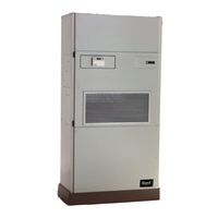
Bard QW2S3DC Literature Assembly (137 pages)
Brand:
Bard
| Category:
Air Conditioner
| Size: 3.67 MB
Table of Contents
Table of Contents
12
General
13
Recovery Equipment Rated for R-410A
13
Leak Detectors
13
Gauge Manifold
13
Attaching Gauge Manifold
13
Attaching Manifold Hose to Schrader Valve
14
Leak Test
14
Evacuation
14
Charging
15
Preliminary Charging Steps
15
Charging the System by Weight
15
Figures
16
Figure 1: Typical AC System Cooling Cycle
16
Figure 2: Typical HP System Cooling Cycle
17
Figure 3 Heating Cycle
18
Troubleshooting the Mechanical System
19
Air Conditioning & Heat Pump - Cooling
19
Low Suction - Low Head Pressure
19
High Suction - Low Head Pressure
19
Low Suction - High Head Pressure
19
High Suction - High Head Pressure
19
Heat Pump - Heating
19
Installation Instructions
24
Getting Other Information and Publications
25
Figures
26
Figure 1
26
Installation
26
Shipping Damage
26
General
26
Installation Wood Framed Walls
26
Wood Framed Installation
26
Application of Sealant to Flanges
27
Masonry Construction Installation
28
Typical Installation
29
Installation through a Window Opening
31
Table of Contents
34
QW General Information
41
Shipping Damage
41
Unit Removal from Skid
41
Handling Unit after Removal from Skid
41
Removal of Wall Bracket from Shipping Location
42
General
42
Minimum Installation Height
42
Duct Work
45
Filters
45
Condensate Drain
45
Mist Eliminator Service
47
Installation
49
Mounting the Unit
49
Wiring - Main Power
52
Wiring - Low Voltage Wiring
52
General
52
Low Voltage Connections
53
Valve and Actuator Installation/Removal
60
Valve Installation
60
Iseries Smart Actuator Removal and Installation
60
Start up
61
Description of Standard Equipment
61
Important Installer Note
62
Phase Monitor
62
Rated CFM
62
Service Hints
62
Adjustments
63
Pressure Service Ports
64
Piping Access to Unit
64
System Start up
64
Sequence of Operation
69
Cooling
69
Heating
69
Geothermal Logic Control
69
Modulating Water Line Control
70
Iseries Smart Actuator
71
Dehumidification
72
Model Features
72
Special Features
72
Closed Loop
83
Circulation System Design
83
Copper Water Coil Application
83
Start up Procedure for Closed Loop System
84
Open Loop (Well System Applications)
86
Water Connections
86
Well Pump Sizing
87
System Start up Procedure for Open Loop Applications
87
Water Corrosion
88
Remedies of Water Problems
88
Lake and Pond Installations
89
Cooling Tower/Boiler Application
91
Service
94
Unbrazing System Components
94
Troubleshooting Geothermal Logic CCM
94
Troubleshooting Water Modulating Actuator Diagnostics
95
Troubleshooting Modulating Water Line Control Board
97
Compressor Solenoid
98
Water to Air Heat Pump
102
Quick Reference Troubleshooting Chart for
102
Ground Source Heat Pump Performance Report
102
Advertisement
Bard QW2S3DC Installation Instructions Manual (73 pages)
Geothermal R-410A Staged Capacity Packaged Heat Pump
Brand:
Bard
| Category:
Heat Pump
| Size: 1.98 MB
Table of Contents
Table of Contents
2
Getting Other Information and Publications for more Information, Contact These Publishers
4
QW General Information QW Model Nomenclature
5
Table 1A Electrical Specifications
6
Table 1B Electrical Specifications
7
Figure 1 Unit Dimensions
8
Figure 2 Removal of Unit from Skid
9
Handling Unit after Removal from Skid
9
Shipping Damage
9
Unit Removal from Skid
9
Figure 3 Proper Handling of Unit after Removal from Skid
10
General
10
Removal of Wall Bracket from Shipping Location
10
Figure 4 Installation of Unit W/Wall Sleeve
11
Minimum Installation Height
11
Figure 5 Shipping Assembly - Bracket Locations
12
Figure 6 Installation of QW Wall Sleeve through a Window Opening
13
Figure 7 Installation with Free Blow Plenum
14
Figure 8 Ducted Application
14
Condensate Drain
15
Duct Work
15
Figure 9 Supply Duct Connections
15
Filters
15
Figure 10A Condensate Drain
16
Figure 10B Optional Rear Drain
16
Figure 10C Rear Drain (Top View)
17
Mist Eliminator Service
17
Figure 11 Removal of Q-TEC ERV
18
Installation
19
Mounting the Unit
19
Figure 12 Remove Locking Screws from Wheels
19
Figure 13 Unit Mounting Without Wall Sleeve
20
Figure 14 Component Location
21
Wiring - Main Power
22
Wiring - Low Voltage Wiring
22
General
22
Table 2 Operating Voltage Range
22
Table 3 Wall Thermostats
22
Low Voltage Connections
23
Figure 15 Low Voltage Wire Harness Plug
23
Figure 16 Remote Thermostat Wiring "X" Option
24
Figure 17 Factory Mounted T-Stat Wiring "D" Option
25
Figure 18 Factory Mounted T-Stat Wiring "H" Opt . 26 Figure 19 Remote Thermostat Wiring "K" Option
27
Figure 20 Fact. Mounted Completestat™ "1" & "3" Opt
28
Figure 21 Fact. Mounted Completestat™ "2" & "4" Opt
29
Figure 22 Fact. Mounted Completestat™ "1" & "3" Opt. and "2" & "4" Opt
30
Valve and Actuator Installation/Removal
31
Valve Installation
31
Iseries Smart Actuator Removal and Installation
31
Figure 23 Valve Actuator Orientation
31
Figure 24 Iseries Smart Actuator Removal
31
Start up
32
Description of Standard Equipment
32
Figure 25 Geothermal Compressor Logic Control Board
32
Important Installer Note
33
Phase Monitor
33
Rated CFM
33
Service Hints
33
Table 4 Indoor Blower Performance
33
Adjustments
34
Figure 26 CO 2 Control Configuration
34
Pressure Service Ports
35
Piping Access to Unit
35
System Start up
35
Figure 27 Fluid Connections W/Ventilation Wall Sleeve
36
Figure 28 Fluid Connections W/O Ventilation Wall Sleeve
37
Table 5 Pressure Table
38
Table 6 Optional Accessories
39
Sequence of Operation Cooling
40
Heating
40
Geothermal Logic Control
40
Modulating Water Line Control
41
Figure 29 Geothermal Compressor Logic Control Board Jumper Designations
41
Figure 30 Modulating Water Line Control
41
Iseries Smart Actuator
42
Figure 31 Iseries Smart Actuator Electrical Terminals
42
Figure 32 Iseries Smart Actuator Temperature Setpoint
42
Dehumidification
43
Model Features
43
Special Features
43
Figure 33 Iseries Smart Actuator Temperature Adjustment
43
Figure 34 Cooling Mode and Dehumidification Mode Circuit Diagrams
44
Table 7A QW2S3D Dehumidification Performance Cooling Full Load
45
Table 7B QW2S3D Dehumidification Performance Dehumidification Full Load
46
Table 8A QW3S3D Dehumidification Performance Cooling Full Load
47
Table 8B QW3S3D Dehumidification Performance Dehumidification Full Load
48
Table 9A QW4S3D Dehumidification Performance Cooling Full Load
49
Table 9B QW4S3D Dehumidification Performance Dehumidification Full Load
50
Table 10A QW5S3D Dehumidification Performance Cooling Full Load
51
Table 10B QW5S3D Dehumidification Performance Dehumidification Full Load
52
Table 11 Dehumidification Relay Logic Board
53
Closed Loop
54
Circulation System Design
54
Copper Water Coil Application
54
Start up Procedure for Closed Loop System
54
Figure 35 Water Temperature and Pressure Test Procedure
55
Open Loop (Well System Applications)
56
Water Connections
56
Figure 36 Piping Diagram
56
Table 12 Constant Flow Valves
56
Well Pump Sizing
57
System Start up Procedure for Open Loop Applications
57
Water Corrosion
58
Remedies of Water Problems
58
Lake and Pond Installations
59
Figure 37 Cleaning Water Coil
59
Figure 38 Water Well System
60
Cooling Tower/Boiler Application
61
Table 13 Water Flow and Pressure Drop
61
Figure 39 Water Source H/P Cooling Cycle
62
Figure 40 Water Source H/P Heating Cycle
63
Service
64
Unbrazing System Components
64
Troubleshooting Geothermal Logic CCM
64
Troubleshooting Water Modulating Actuator Diagnostics
65
Figure 41 LED Fault Illumination
65
Figure 42 Iseries Smart Actuator
65
Table 14 Multi-Status LED
65
Table 15 Temperature F Vs. Resistance R of Temperature Sensor
66
Troubleshooting Modulating Water Line Control Board
67
Figure 43 Modulating Water Line Control Board
67
Table 16 Modulating Water Line Control Board Logic
67
Compressor Solenoid
68
Table 17 Solenoid Coil Resistance
68
Troubleshooting GE ECM™ Blower Motors
69
Figure 44 Control Disassembly
70
Figure 45 Winding Test
70
Figure 46 Drip Loop
70
Quick Reference Troubleshooting Chart for Water to Air Heat Pump
71
Ground Source Heat Pump Performance Report
72
Advertisement
Related Products
Bard QW2S3DA
Bard QW2S3DB
Bard QW2S3-A
Bard QW2S3-B
Bard QW2S3-C
Bard QW2S3DA0Z
Bard QW2S3DB0Z
Bard QW2S3DC0Z
Bard QW5S3DA
Bard QW4S3DA0Z
Bard Categories
Air Conditioner
Heat Pump
Medical Equipment
Furnace
Controller
More Bard Manuals
Login
Sign In
OR
Sign in with Facebook
Sign in with Google
Upload manual
Upload from disk
Upload from URL