Sign In
Upload
Manuals
Brands
Bard Manuals
Air Conditioner
MEGA-TEC W180B
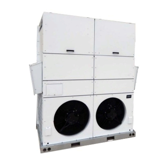
Bard MEGA-TEC W180B Manuals
Manuals and User Guides for Bard MEGA-TEC W180B. We have
1
Bard MEGA-TEC W180B manual available for free PDF download: Service Instructions Manual
Bard MEGA-TEC W180B Service Instructions Manual (68 pages)
Wall-Mount Air Conditioner
Brand:
Bard
| Category:
Air Conditioner
| Size: 4.44 MB
Table of Contents
Table of Contents
2
General Information
4
Additional Publications
4
General
4
Multi-Stage Cooling System
4
Shipping Damage
4
Wall-Mount Air Conditioner Units
4
Figures
6
Using the TEC-EYE TM
6
Using the TEC-EYE
6
TEC-EYE Hand-Held Service Tool
6
Figure 1 TEC-EYE Display and Interface
6
Figure 2 TEC-EYE Connection to Unit Control
6
Main Status Screen
7
Quick Menu
7
Figure 3 Quick Menu Icons
7
Setpoints
7
TEC-EYE Acronyms
7
TEC-EYE Menu Structure
7
LC6000/TEC-EYE Passwords (Defaults)
7
Unit Status Messages
8
Information
9
A/C Circuit Information
9
Air Path Information
9
Figure 4 Cool and Heat Setpoints
9
Figure 5 MEGA-TEC Air Paths and Refrigeration Circuits
9
Figure 6 Unit Air Path Information
9
24 Hour Run Time
10
Figure 7 Last 24 Hour Tracking
10
Figure 8 A/C Circuit Measurements
10
Software Version
10
Alarm Log
11
Executing a Self Test
11
Figure 10 Executing Self Test
11
Figure 9 Software Version
11
Self Test Parameter Descriptions
11
Software Versioning Guide
11
Configuration File
12
Figure 11 Restoring Factory Default Settings
12
Figure 12 Restoring Factory Default Settings - Remove USB Device
12
Reset to Factory Defaults
12
Operation
13
Unit On/Off
13
Alarm Adjustment
13
Acknowledging Alarms
13
Clearing Alarms
13
Clearing Alarm Logs and Counters
13
Exporting Alarm Logs
13
Figure 13 Clearing All Alarms
13
Figure 14 Clearing Alarm Logs and Counters
13
Exporting 7 Day Logs
14
Unit Address and Zone
14
Temperature Control
14
Temperature Control Components
14
Figure 15 Changing Zone
14
Figure 16 Adjusting Return Air Temperature Sensor
14
Return Air Temperature Sensor
14
Return Air Temperature Sensor Alarm
14
Cooling
15
Figure 17 Cooling (with Economizer)
15
LC6000 Control
15
Orphan Mode
15
Temperature Control Operation
15
Figure 18 Cooling (Without Economizer)
16
Figure 19 Heating
16
Figure 20 Adjusting Cooling Differentials
16
Heating
16
Electronic Expansion Valve (EEV)
17
EEV Components
17
EEV Instructions for Vacuum, Reclaim, Charge Unit
17
Electronic Expansion Valve
17
Figure 21 Adjusting Heating Differentials
17
Figure 22 Overriding EEV Output
17
Figure 23 Electronic Expansion Valve (EEV) and Service Tool
17
Figure 24 Adjusting Suction Sensor/Transducer Pressure Values
18
Figure 25 Voltage to Pressure: Suction Pressure Transducer
18
Suction Pressure Alarm
18
Suction Pressure Transducer
18
Suction Temperature Sensor
18
System Pressures
18
Troubleshooting the Suction Pressure Transducer
18
Suction Temperature Sensor Alarm
19
EEV Operation
19
Additional EEV Alarms
19
EEV Superheat Control
19
Low Superheat Alarm
19
Indoor Airflow
19
Indoor Airflow Components
19
Blower
19
Figure 26 Adjusting Suction Temperature Sensor Values
19
Figure 27 Putting Blower Output into Override Mode
19
Blower Status Switch
20
Figure 28 Dirty Filter Switch and Blower Status Switch
20
Figure 29 Verifying Differential Airflow Status
20
Table 6
20
Rated Airflow
20
Indoor Blower Performance
20
Maximum ESP of Operation: Electric Heat Only
20
Blower Status Alarm
21
Filters
21
Dirty Filter Switch
21
Dirty Filter Alarm
21
Figure 30 Dirty Filter Switch and Filter Indicator Light
21
Balanced Climate TM Operation
22
Blower Speed Control
22
Figure 31 Verifying Filter Light Status
22
Figure 32 Overriding Fliter Light Output
22
Filter Indicator Light
22
High Sensible Operation
22
Indoor Airflow Operation
22
Additional Indoor Airflow Alarms
23
Supply Air Temperature Sensor Alarm
23
Condenser Fan
23
Condenser Fan Components
23
Figure 33 Enabling/Disabling High Sensible or Balanced Climate Operation
23
Figure 34 Enabling Fan Override
23
Blower Speed Settings
23
Liquid Pressure Sensor
24
Discharge/Liquid Pressure Transducer Alarm
24
Figure 35 Adjusting Discharge/Liquid Transducer Pressure Values
24
Figure 36 Voltage to Pressure: Discharge/Liquid Pressure Transducer
24
Liquid Temperature Sensor
24
Troubleshooting the Discharge/Liquid Pressure Transducer
24
Condenser Fan Operation
25
Condenser Fan Speed Control
25
Outdoor Temperature Sensor
25
Compressor
25
Compressor Components
25
Figure 37 Adjusting Discharge/Liquid Temperature Input
25
Figure 38 Condenser Fan Liquid/Discharge Pressure Setpoint
25
Table 10 Condenser Fan Nominal Speed
25
Brownout Protection W/Adjustment
26
Compressor Control Module (CCM)
26
Delay-On-Make Timer
26
High Pressure Detection
26
Short Cycle Protection/Delay-On-Break
26
Test Mode
26
Figure 39 8201-169 Compressor Control Module
27
High Pressure Safety Switch
27
Phase Monitor
27
Refrigerant High Pressure Alarm
27
Crankcase Heater
28
Compressor Operation
28
Figure 40 Adjusting Compressor Delays
28
Figure 41 Verifying Compressor Output Status
28
Additional Compressor Alarms
29
Refrigerant Low Pressure Alarm
29
Economizer
29
Economizer Components
29
Actuator
29
Dust Sensor
29
Figure 42 Overriding Compressor Outputs
29
Figure 43 Damper Override
29
Dust Sample
30
Figure 44 Dust Sensor
30
Figure 45 Verifying Dust Sample Output Status
30
Figure 46 Overriding Dust Sample Output
30
Damper Blade
31
Dust Sensor Failure Alarm
31
Figure 47 Adjusting Dust Sensor Alarm Setpoint
31
Figure 48 W180 Damper Blades
31
High Dust Limit Alarm
31
Damper Failed to Close Alarm
32
Damper Failed to Open Alarm
32
Damper Switch
32
Figure 49 Damper Blade Position
32
Figure 50 Damper Switch
32
Figure 51 Outdoor Temperature Sensor
33
Figure 52 Outdoor Humidity Sensor
33
Mixed Air Temperature Sensor
33
Outdoor Humidity Sensor Failure Alarm
33
Outdoor Temperature and Humidity Combination Sensor
33
Outdoor Temperature Sensor Failure Alarm
33
High Mixed Air Temperature Alarm
34
Low Mixed Air Temperature Alarm
34
Economizer Operation
34
Figure 53 Mixed Air Temperature Sensors
34
Figure 54 Economizer Setup
34
Figure 55 Economizer Setup - Dry Bulb Control
35
Figure 56 Economizer Setup - Temphum Control
35
Figure 57 Economizer Setup - Enthalpy Control
35
Economizer Operation - Minimum Position
36
Miscellaneous Components
36
Supply Temperature Sensor
36
Figure 58 Supply Air Temperature Sensor
36
Table 11 Economizer Default Settings
36
Supply Temperature Sensor Failure Alarm
37
Emergency Cooling Mode
37
Emergency Cooling − Orphan Mode
37
Emergency Ventilation Mode
37
Electric Heat Option
37
Electric Heat Components
37
Electric Heating Element
37
Figure 59 Emergency Cool − Orphan Mode
37
Figure 60 Adjusting Return Air Alarm Settings
37
Electric Heat Operation
38
Thermal Overload
38
Electric Reheat Dehumidification
38
Figure 61 Verifying Electric Heat Output Status
38
Figure 62 Overriding Electric Heat Output
38
Figure 63 Electric Reheat Dehumidification
38
Electric Reheat Dehumidification Operation
39
Unit Disable Option
39
Figure 64 Dehumidification Control (°F)
39
Table 12 Cooling Capacity Limitation
39
Serial/Model Number Configuration
40
Figure 65 Unit Disable Option
40
Figure 66 Verifying Damper Power Output Status
40
Figure 67 Overriding Damper Output
40
Figure 68 Serial/Model Number Configuration
40
Figure 69 MEGA-TEC Model Nomenclature
42
Refrigerant Information
43
General
43
Topping off System Charge
43
Safety Practices
43
Important Installer Note
43
R410-A Refrigerant Charge
43
Pressure Service Ports
44
Table 12
44
Table 13 W180 Cooling Pressures
44
Maintenance & Troubleshooting
45
Standard Maintenance Procedures
45
Figure 70 Sensors and Peripheral Devices
46
Figure 71 Supply and Return Air Sensors
47
8301-089 Outdoor Temperature/Humidity Sensor
48
8301-089 Sensor Connections
48
Figure 72 8301-089 Sensor Electrical Connections and DIP Switches
48
Figure 73 8301-089 Sensor Terminal Connections
48
8301-089 Outdoor Temperature Sensor Troubleshooting
49
Figure 74 8301-089 Sensor: Temperature Probe Troubleshooting
49
Table 14 8301-089 Sensor: Temperature/Resistance
50
8301-089 Humidity Sensor Test Value Outputs
51
8301-089 Outdoor Humidity Sensor Troubleshooting
51
Figure 75 8301-089 DIP Switch/Output Configuration
51
Figure 76 8301-089 Sensor: Humidity Probe Troubleshooting
51
Table 15 8301-089 Sensor: Humidity/Ma
52
8620-296 Supply Air Sensor/Return Air Sensor/Mixed Air Sensor/Suction Sensor/Liquid Sensor/Freeze Sensor
53
Table 15
53
Table 16 8620-296 Sensor: Temperature/Resistance Curve J
53
8301-057 Blower Status Switch/Dirty Filter Switch
54
Figure 77 8301-057 Air Differential Switch
54
Compressor Solenoid
55
Compressor Solenoid Test Procedures
55
Figure 78 Compressor Solenoid Location
55
8612-064 Dust (Particulate) Sensor Control Board
56
8612-064 Control Board Output Signal Not Responsive
56
Figure 79 8612-064 Dust Sensor Alarm Board
56
8301-091 Dust (Particulate) Sensor
57
Table 17
57
Table 17 8301-091 Sensor: Dust/Volts
57
Variable Speed Blower/Condensate Fan
58
Figure 80 Fan Terminals
58
Maintenance
58
LED Warning/Status Codes
59
Table 18 Blower/Condenser Fan Troubleshooting
59
Table 19 Blower/Condenser Fan Motor Flash Codes
59
Modbus Troubleshooting
60
Figure 81 PLC Communication Wires
60
Figure 82 Expansion Module Communication Wires
60
Figure 83 Blower/Condenser Fan Communication Wires
60
Table 20 Modbus Device Communication Wires
60
Figure 84 Communication Wires in Terminal Block
61
Figure 85 DIP Switch Location
61
Figure 86 Correct DIP Switch Settings
61
Figure 87 TEC-EYE Blower 1 Screen
61
Figure 88 TEC-EYE Condenser Fan 1 Screen
62
Alarm Index
63
Figure 89 Ventilation Airflow Paths
66
I/O Layout
67
Figure 90 I/O Layout
67
Figure 91 I/O Layout
68
Advertisement
Advertisement
Related Products
Bard W18L1
Bard W18A2
Bard MULTI-TEC W18LAPA
Bard W18LA-A
Bard W18LB-A Series
Bard W18LB-A05
Bard W18LB-A0Z
Bard W18LB-A08
Bard W18LB-A10
Bard MULTI-TEC W18LAPA0Z
Bard Categories
Air Conditioner
Heat Pump
Medical Equipment
Furnace
Controller
More Bard Manuals
Login
Sign In
OR
Sign in with Facebook
Sign in with Google
Upload manual
Upload from disk
Upload from URL