Bard 11EER WH Series Manuals
Manuals and User Guides for Bard 11EER WH Series. We have 2 Bard 11EER WH Series manuals available for free PDF download: Installation Instructions Manual
Advertisement
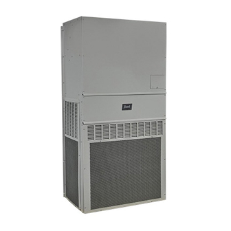
Bard 11EER WH Series Installation Instructions Manual (45 pages)
Wall Mount Heat Pump
Table of Contents
Advertisement