Sign In
Upload
Manuals
Brands
Alcatel-Lucent Manuals
Gateway
PacketStar PSAX 2300
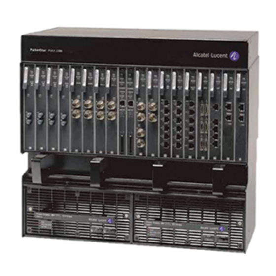
Alcatel-Lucent PacketStar PSAX 2300 Manuals
Manuals and User Guides for Alcatel-Lucent PacketStar PSAX 2300. We have
1
Alcatel-Lucent PacketStar PSAX 2300 manual available for free PDF download: Installation Manual
Alcatel-Lucent PacketStar PSAX 2300 Installation Manual (122 pages)
Multiservice Media Gateway
Brand:
Alcatel-Lucent
| Category:
Gateway
| Size: 3.14 MB
Table of Contents
Installation Guide
1
Table of Contents
3
List of Figures
8
List of Tables
10
Copyright, Legal, and Safety Information
13
Copyright
13
Trademarks
13
Notices
13
Warranty Information
13
Software and Hardware Limited Warranties
13
Warranty Warnings
14
Regulatory Standards Compliance
15
Safety Compliance
15
Electromagnetic Compatibility Compliance
15
Telecommunications Compliance
15
Regulatory Statements
15
USA Regulatory Statements
15
FCC Part 15
15
FCC Part 68
15
Underwriters Laboratories, UL 1950
17
Canadian Regulatory Statements
17
Ices-003
17
Issue 8
17
European Union Regulatory Statement
18
CE Marking
18
Japanese Regulatory Statements
22
Jate
22
VCCI
22
CISPR 22, en 55022, AS/NZS-3548 Class a EMC Regulatory Statement
22
Safety Information
22
Electrostatic Discharge (ESD) Precautions
22
JATE Approved Modules
22
Floor Covering
23
Grounding Wrist Straps
23
Humidity
23
ESD Grounding Wrist Strap
23
Clothing
24
Handling Chassis, Modules, and Components
24
About this Guide
25
Purpose of this Guide
25
Audience for this Guide
25
What You Should Know
25
Related Reading
26
Printed Documents
26
Other Publications
26
Conventions Used in this Document
26
Text Types Used in this Document
26
Icons and Symbols
26
Text Conventions
26
Technical Support
27
About Alcatel-Lucent Products
27
For more Information
27
About the Packetstar PSAX Product Family
27
PSAX 1000 Multiservice Media Gateway
27
PSAX 1250 Multiservice Media Gateway
28
PSAX 2300 Multiservice Media Gateway
28
PSAX 4500 Multiservice Media Gateway
28
Comments on this Guide
29
Getting Started
31
Overview of this Section
31
Using the Installation Checklist
31
Product Modification or Repair
31
System Hardware Components
31
Hardware
31
Supplied Accessories
32
Packetstar PSAX 2300 Multiservice Media Gateway
32
System Software Upgrade Kit
33
System Hardware Specifications
33
Chassis Specifications
33
PSAX 2300 Chassis Hardware Specifications
33
System Environmental Specifications
33
Power Supply Module Specifications
34
Stratum 3-4 Module Specifications
34
CPU2 Module Specifications
35
CPU4 Module Specifications
35
Alarm Module Specifications
36
Packetstar I/O and Server Modules Specifications
36
Physical Hardware Specifications for PSAX I/O and Server Modules
36
Physical Hardware Specifications for the Alarm Module
36
Ventilation Requirements
36
Restricted-Access Facilities
37
Unrestricted-Access Facilities
37
-48 V DC Power Wire
38
Cable Management Requirements
38
Cabling Requirements
38
Customer Supplied Cabling
38
Equipment Grounding Requirements
38
Ground Wire
38
Alarm Cable
39
Cabling Supplied with the Chassis
39
Ethernet Cable
39
External Clock Input Cable
39
Network Cabling
39
Status/Control Cable
39
Tools and Materials Requirements
39
Tools and Materials to Install the PSAX 2300 Chassis
40
Installing the PSAX 2300 System
41
Overview of this Section
41
Before You Begin
41
Installing the Hardware
42
Attaching the Mounting Brackets to the Chassis
42
Flush-Mounted Position Using the 23-In. Mounting Brackets
43
Flush-Mounted Position Using the 19-In. Mounting Brackets
43
MID-Mounted Position Using the 23-In. Mounting Brackets
44
Mounting Brackets for 23-In. Equipment Rack with 1.00 Inch Mounting Holes
45
Mounting the Chassis
46
Securing the Chassis to a 23-In. Equipment Rack (Flush-Mount Position)
47
Securing the Chassis to a 23-In. Equipment Rack (MID-Mount Position)
47
Grounding the Chassis
48
Securing the Chassis to a 19-In. Equipment Rack (Flush-Mount Position)
48
Connecting the Facility Power Cables
49
Attaching the Ground Wire to the Ground Lug
49
Attaching the Power Wires to the Terminal Blocks
50
Completed Installation of Facility Power and Ground Wires
51
Installing the Common Equipment Modules
52
Installing the Power Supply Modules
52
Inserting the -48 V DC Power Supply Module into the Chassis
52
Installing the Stratum 3-4 Modules
53
Securing the Power Supply Module to the Chassis
53
Installing the Stratum 3-4 Modules
54
Installing the CPU4 or CPU2 Modules
54
Installing the Stratum 3-4 Module
54
Installing the Cpun Modules
55
Installing the Alarm Module (Model 20N79)
56
Locking Tab on the Cpun Module Faceplate
56
Making Common Equipment Connections
57
Connecting the Console Workstation
57
Locking Tab on Alarm Module Faceplate
57
Connecting the Console Serial Interface Cable
58
Connecting the Ethernet Cable
58
Connecting the Chassis to the Ethernet Network
59
Connecting the Console Connection to a Dialup Modem
59
Connecting the Alarm Module (Model 20N79) to the CO
60
Connecting the External Facility Clock
60
Applying DC Power
61
Applying Power to the System
61
Connecting the CO Alarm, Sensors, and Remote Controls to the Chassis
61
Checking LED Indicators
62
Checking the Status LED Indicators
62
Power Supply Module Status Indicators
63
Stratum 3-4 Module Status Indicators
63
Status Indicators on the -48 V DC Power Supply Module
63
Power Supply Module Status LED Indicators
63
CPU4 Module Status Indicators
64
CPU4 Module Status LED Indicators
64
PSAX Stratum 3-4 Module Status Indicators
64
CPU2 Module Status Indicators
65
CPU2 Module Status LED Indicators
65
Installing the I/O and the Server Modules
65
Locking Tab on the I/O and Server Module Faceplate
66
Connecting the Network Cabling
67
Configuring and Testing the System
67
Performing Maintenance
69
Overview of this Section
69
Shutting down the System
69
Removing Modules from the Chassis
70
Removing a DC Power Supply Module
70
Removing the Stratum 3-4 Module
70
Removing an I/O or a Cpun Module
71
Removing an I/O Module or a CPU2 Module
71
Locking a Module in the PSAX 1000 Chassis
72
Locking Tab on the Module (Shown in a PSAX 4500 Chassis)Removing I/O or Cpun Modules with
72
Removing a Server Module
73
Removing Server Modules with Locking Tabs
73
Removing the Alarm Module
74
Locking Tab on the Alarm Module Faceplate
74
Replacing Blank Faceplates
75
Installing Blank I/O/CPU Faceplates
75
Removing Blank I/O/CPU Faceplates
76
Inserting Blank Faceplate into the Chassis Front Panel
76
Replacing the Chassis Air Filter
77
Replacing the Power Supply Module Fuses
78
Replacing the Air Filter
78
Shipping the System
79
Shipping a Standalone System
79
Replacing the Power Supply Module Fuse
79
Begin
79
End
79
Shipping a Rack-Mounted System
80
Common Equipment Module Connections
81
Overview of this Appendix
81
CPU4 Module Connectors
81
CONSOLE Connector
81
ETHERNET1 and ETHERNET2 Connector
81
ETHERNET1 and ETHERNET2 Connector Pin Locations
81
CPU4 Module CONSOLE Connector Pin Assignments
81
CONSOLE Connector
82
CPU2 Module Connectors
82
ETHERNET Connector
82
ETHERNET Connector Pin Locations
82
A Common Equipment Module Connections
82
CPU2 Module CONSOLE Connector Pin Assignments
82
CPU4 Module ETHERNET1 and ETHERNET2 Connector Pin Assignments
82
Console Cable Adapters
83
CPU2 Module ETHERNET Connector Pin Assignments
83
RJ-12-To-DB25 Adapter Pin Assignments
83
RJ-12-To-DB9 Adapter Pin Assignments
83
Alarm Module Connectors
84
ALARM Connector
84
Stratum 3-4 Connector
84
ALARM Connector Pin Locations on the Alarm Module
84
Stratum 3-4 Module RJ-45 Connector Pin Assignments
84
ALARM Cable with 26-Pin Connector and Pigtail
85
ALARM Connector Pin Assignments and Cable Pigtail Color Code
85
STATUS/CONTROL Connector
86
STATUS/CONTROL Connector Pin Locations on the Alarm Module
86
STATUS/CONTROL Cable with 44-Pin Connector and Pigtail
87
STATUS/CONTROL Connector Pin Assignments and Cable Pigtail Color Code
87
(Comcode 300164282)
88
Orderable Parts
89
Overview of this Appendix
89
Blank Faceplate Modules
89
Replacement Air Filters
89
Orderable Blank Faceplates
89
Chassis Air Filter
89
Replacement Fuses
90
Orderable Cables
90
Orderable Fuse Kits
90
Orderable I/O and Common Equipment Cables
90
Module Information
93
Overview of this Appendix
93
Performance and Power Specifications for Modules
93
Performance and Power Specifications for the PSAX Modulesperformance and Power Specifications for
93
Module Connections
98
PSAX I/O Module Connectors
98
Interface Types by I/O Module
101
Interface Type by I/O Module Type
101
Index
107
Installation Checklist
115
Overview of this Section
115
Checklists
115
Checklist-1. before Starting the Installation
115
Checklist-2. Installing the Hardware
116
Checklist-3. Making the Common Equipment Connections
117
Advertisement
Advertisement
Related Products
Alcatel-Lucent Premium REFLEXES OmniPCX 4400
Alcatel-Lucent PSS-4
Alcatel-Lucent 500V Series
Alcatel-Lucent 6Ve.B2131
Alcatel-Lucent 6Vz.A2131
Alcatel-Lucent 9966
Alcatel-Lucent CellPipe 7130
Alcatel-Lucent CellPipe 7130 RG 5Ve.A2000
Alcatel-Lucent CellPipe 7130 RG 5Ve.B2000
Alcatel-Lucent CellPipe 7230 BG 100V Series
Alcatel-Lucent Categories
Switch
Telephone
Network Router
IP Phone
Network Hardware
More Alcatel-Lucent Manuals
Login
Sign In
OR
Sign in with Facebook
Sign in with Google
Upload manual
Upload from disk
Upload from URL