
Related Manuals for Alcatel-Lucent PacketStar PSAX 2300


Summary of Contents for Alcatel-Lucent PacketStar PSAX 2300
-
Page 1: Installation Guide
® PacketStar PSAX 2300 Multiservice Media Gateway Installation Guide PSAX Multiservice Media Gateways ® for PacketStar 255-700-161 Issue 4 April 2008... - Page 2 This material is protected by the copyright and trade secret laws of the United States and other countries. It may not be reproduced, distributed, or altered in any fashion by any entity (either internal or external to Alcatel-Lucent), except in accordance with applicable agreements, contracts, or licensing, without the express written consent of Alcatel-Lucent and the business management owner of the material.
-
Page 3: Table Of Contents
Table of Contents List of Figures ............viii List of Tables . - Page 4 About Alcatel-Lucent Products ........
- Page 5 Table of Contents Alarm Module Specifications ..........12 PacketStar I/O and Server Modules Specifications .
- Page 6 Table of Contents Connecting the Alarm Module (Model 20N79) to the CO ......36 Connecting the CO Alarm, Sensors, and Remote Controls to the Chassis .
- Page 7 Table of Contents ETHERNET Connector ............58 Console Cable Adapters .
-
Page 8: List Of Figures
PacketStar PSAX 2300 Multiservice Media Gateway ........ - Page 9 List of Figures ® PacketStar PSAX 2300 Multiservice Media Gateway Installation Guide, Issue 4 255-700-161...
-
Page 10: List Of Tables
List of Tables JATE Approved Modules ............xxii Text Conventions . - Page 11 List of Tables Checklist-4. Applying Power to the System ......... . . Checklist-3 Checklist-5.
- Page 12 List of Tables ® PacketStar PSAX 2300 Multiservice Media Gateway Installation Guide, Issue 4 255-700-161...
-
Page 13: Copyright, Legal, And Safety Information
7R/E, ConnectReach, STINGER, PacketStar, Navis, Lucent, Lucent Technologies, Alcatel-Lucent, and the Alcatel-Lucent logo are registered trademarks of Alcatel-Lucent. Other product and brand names mentioned in this guide are trade- marks or registered trademarks of their respective owners. Notices The information in this document is for informational use only, is subject to change without notice, and should not be construed as a commitment by Alcatel-Lucent. -
Page 14: Warranty Warnings
Equipment failure due to inade- quate maintenance will void your equipment warranty. WARNING: Use only air filters supplied by Alcatel-Lucent in your PSAX chassis. Use of other air filters will void your equipment warranty. WARNING: Damage to the module and/or chassis, that is caused by excessive force, when installing the modules will void your equipment warranty. -
Page 15: Regulatory Standards Compliance
Copyright, Legal, and Safety Information Regulatory Standards Compliance Regulatory Standards Compliance The PacketStar PSAX 2300 Multiservice Media Gateway, model 23S00, is compliant with the listed safety, electromagnetic compatibility (EMC), and telecommunications standards. Applicable statements are provided in the next subsection. - Page 16 FCC registration number, in addition to other infor- mation. You must provide this information to the telephone company, if they request it. The FCC requires Alcatel-Lucent to provide you with the following information: 1. This equipment has digital service interface capabilities using RJ-48C and RJ- 48H connectors.
-
Page 17: Underwriters Laboratories, Ul 1950
Copyright, Legal, and Safety Information Regulatory Statements Underwriters This product is UL Listed only when supplied with the following assemblies: Laboratories, UL 1950 Model No. Name 23S00 PSAX 2300 Chassis 23N11 PSAX 2300/4500 -48 V dc Power Supply (two required) 23N05 PSAX 2300 Stratum 3–4 (two required) 20N20... -
Page 18: European Union Regulatory Statement
EU-regulativer CE-mærkning Alcatel-Lucent erklærer hermed at PacketStar PSAX 1000 (-48 V dc og 220 v veksel- strøm), PSAX 1250 (-48 V dc og 220 v vekselstrøm), PSAX 2300, og PSAX 4500 Multiservice Media Gateways overholder kravene i følgende EU-direktiver: •... - Page 19 Euroopan unionin sääntelystandardi CE-merkintä Alcatel-Lucent vakuuttaa täten, että PacketStar PSAX 1000 (-48 V dc ja 220 V vaih- tovirtaa), PSAX 1250 (-48 V dc ja 220 V vaihtovirtaa), PSAX 2300, ja PSAX 4500 Multiservice Media Gatewayt täyttävät seuraavien neuvoston direktiivien keskeiset vaatimukset ja asiaankuuluvat määräykset:...
- Page 20 Norm van de Europese Unie CE-markering Alcatel-Lucent verklaart hierbij dat de PacketStar PSAX 1000 (-48 V dc en 220V wisselstroom), PSAX 1250 (-48 V dc en 220V wisselstroom), PSAX 2300, en PSAX 4500 Multi Service Media Gateways voldoen aan de essentiële vereisten en andere relevante bepalingen van de volgende Richtlijnen van de Raad: •...
- Page 21 Europeiska unionens standardförordning CE-märkning Alcatel-Lucent deklarerar härmed att PacketStar PSAX 1000 (-48 V likström och 220 V växelström), PSAX 1250 (-48 V likström och 220 V växelström), PSAX 2300, och PSAX 4500 Multiservice Media Gateways uppfyller de väsentliga kraven och andra relevanta bestämmelser som gäller enligt följande Europarådsdirektiv:...
-
Page 22: Japanese Regulatory Statements
Copyright, Legal, and Safety Information Safety Information Japanese Regulatory Statements VCCI This is a Class A product based on the standard of the Voluntary Control Council for Interference by Information Technology Equipment (VCCI). If this equipment is used in a domestic environment, radio disturbance may occur, in which case, the user may be required to take corrective actions. -
Page 23: Grounding Wrist Straps
Copyright, Legal, and Safety Information Electrostatic Discharge (ESD) Precautions Grounding Wrist Straps Using a grounding wrist strap (see Figure 1) is recommended when in direct contact with the PSAX system and its components. A wrist strap grounding point is provided on the upper left corner of the PSAX 2300 chassis front panel. -
Page 24: Clothing
Copyright, Legal, and Safety Information Electrostatic Discharge (ESD) Precautions • Maintain the relative humidity of the room between 40 and 60 percent. • To avoid damage to equipment, do not allow the humidity to increase to the level where condensation would appear on surfaces. Clothing When working with the PSAX system, avoid wearing clothing made from wool or synthetic materials. -
Page 25: About This Guide
About This Guide Purpose of This Guide ® The PacketStar PSAX 2300 Multiservice Media Gateway Installation Guide pro- vides information about the following: • Observing appropriate safety, electrostatic discharge, and ventilation precautions in setting up and operating the PSAX 2300 Multiservice Media Gateway system •... -
Page 26: Related Reading
Related Reading Related Reading Printed Documents For your convenience, the PSAX documents are available in printed form. You can order these documents through the Alcatel-Lucent Customer Information Center Web site at: http://www.cic.lucent.com/. Other Publications Numerous books are currently available on the subject of basic telecommunications technology and specific protocols. -
Page 27: Technical Support
Identifies additional information pertinent to the text preceding this note. Technical Support If you experience a problem with the PSAX system, refer to the Alcatel-Lucent Prod- uct Warranty Registration Information, which accompanied your shipment, for instructions on obtaining support in your area. -
Page 28: Psax 1250 Multiservice Media Gateway
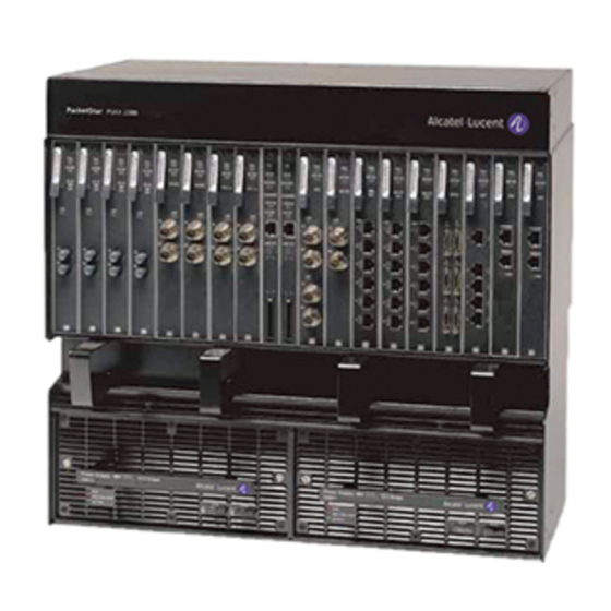
PSAX 2300 Multiservice Media Gateway The PacketStar PSAX 2300 Multiservice Media Gateway offers carrier-grade, high- density multiservice ATM access functions. Designed as the multiservice media gate- way for the central office or for a large enterprise customer, the PSAX 2300 system provides network access for time-division multiplex voice, frame relay, 10/100BASE-T Ethernet, and ATM data applications. -
Page 29: Comments On This Guide
® tion GuideTo comment on the PacketStar PSAX <xxxx> Module User Guide, go to the Online Comment Form at http://www.lucent-info.com/comments/enus/ or e-mail your comments to the Comments Hotline (comments@alcatel-lucent.com). Include the following information: ® Title: PacketStar PSAX 2300 Multiservice Media Gateway Installation GuidePack- ®... - Page 30 About This Guide Comments on This Guide ® PacketStar PSAX 2300 Multiservice Media Gateway Installation Guide, Issue 4 255-700-161...
-
Page 31: Getting Started
PSAX 2300 system. Alcatel-Lucent is not responsible for the safety or the perfor- mance of a modified Alcatel-Lucent product. Do not remove or attempt to repair or modify any components inside the PSAX 2300 chassis. Do not attempt to repair or modify any failed I/O or server modules. -
Page 32: Supplied Accessories
(see your Alcatel-Lucent account manager for ordering information) • Input/output (I/O) and server modules (see your Alcatel-Lucent account manager for ordering information). Technical information can be found in Appendix C. • Blank faceplate modules—required for empty I/O and server slots (see Appendix B... -
Page 33: System Software Upgrade Kit
• One 14-foot shielded cable with RJ-12 connectors (console cable) • Four insulated cable clamps (PN 06-CC8122, for #10 AWG power supply cable) If your kit is not complete, contact your Alcatel-Lucent account manager. System Software Upgrade Kit A separately orderable system software upgrade kit is available in a separate envelope with the following item: •... -
Page 34: Power Supply Module Specifications
Getting Started System Hardware Specifications Table 4. System Environmental Specifications (Continued) Specification Description 60 meters (197 feet) below sea level to 4,000 meters (13,123 Operating altitude range feet) above sea level -40° to 70° C (-40° to 158° F) Storage temperature range 0% to 90% noncondensing Storage humidity range Power Supply Module Specifications... -
Page 35: Cpu4 Module Specifications
Getting Started System Hardware Specifications Table 6. Stratum 3–4 Module Specifications (Continued) Specification Description Accuracy Stratum 3 or 4, selectable External clock input ANSI/ITU-T Composite (64 kHz), T1BITS (1.544 MHz), E1ETSI (2.048 MHz), and DS0A Composite (64 kHz) Connector One RJ-45 (with either 120 ohm or 75 ohm termination) CPU4 Module Specifications The specifications for the PSAX CPU4 module are given in Table 7. -
Page 36: Alarm Module Specifications
Getting Started Ventilation Requirements Alarm Module Specifications Table 9 shows the physical and environmental hardware specifications for the Alarm module. Table 9. Physical Hardware Specifications for the Alarm Module Specification Description Dimensions 17.3 cm H x 2.41 cm W x 23.2 cm D (6.8 in. -
Page 37: Restricted-Access Facilities
Getting Started Ventilation Requirements Refer to ”Warranty Warnings” on page xiv for additional information concerning ade- quate ventilation. DANGER: Air vents in the chassis are provided to protect it from overheating. These vents must not be blocked. Inadequate air flow may result in overheating and possible equipment failure. -
Page 38: Equipment Grounding Requirements
Getting Started Equipment Grounding Requirements Equipment Grounding Requirements The grounding of the PSAX 2300 chassis is provided through the ground lug on the rear of the chassis. The chassis grounding point must be connected to a common elec- trical ground to provide proper protection. See ”Grounding the Chassis” on page 24 for grounding instructions. -
Page 39: External Clock Input Cable
Ethernet cable. Alarm Cable One 3.7-meter (12-feet) shielded Alcatel-Lucent cable with HD-22 26-pin subminia- ture D-type receptacle (female) on one end and a pigtail on the other is orderable with the Alarm module to connect the PSAX 2300 system to the CO audible and visible alarm system. -
Page 40: Tools And Materials To Install The Psax 2300 Chassis
R-2916 L9 Nylon lacing cord ITE-7173 Cletop connector cleaning system Local purchase Assorted flathead screwdrivers Local purchase Assorted Phillips screwdrivers Local purchase Nutdriver set For Alcatel-Lucent installers only. ® PacketStar PSAX 2300 Multiservice Media Gateway Installation Guide, Issue 4 255-700-161... -
Page 41: Installing The Psax 2300 System
PSAX Multiservice Media Gateway Safety Guidelines and “Getting Started” on page 7. If you have any questions about or problems with the prepa- ratory tasks, be sure to contact Alcatel-Lucent Technical Support first before beginning the actual installation of the equipment (see “Technical Support” on page 3). -
Page 42: Installing The Hardware
Installing the PSAX 2300 System Installing the Hardware 4 Verify that the input power from your facility power source meets the specifica- tions in “Power Supply Module Specifications” on page 10 for the type of power supply you have in your system. 5 Obtain the tools you will need during installation (see “Tools and Materials Requirements”... -
Page 43: Flush-Mounted Position Using The 23-In. Mounting Brackets
Installing the PSAX 2300 System Installing the Hardware Figure 3. Flush-Mounted Position Using the 23-in. Mounting Brackets Figure 4. Flush-Mounted Position Using the 19-in. Mounting Brackets ® PacketStar PSAX 2300 Multiservice Media Gateway Installation Guide, Issue 4 255-700-161... -
Page 44: Mid-Mounted Position Using The 23-In. Mounting Brackets
Installing the PSAX 2300 System Installing the Hardware Figure 5. Mid-Mounted Position Using the 23-in. Mounting Brackets The supplied mounting brackets have mounting holes spaced for 4.5 cm (1.75 in.) spaced equipment rack mounting holes. The mounting hole spacing for the 48.26 cm (19 in.) mounting brackets is 3.175 cm (1.25 in). -
Page 45: Mounting Brackets For 23-In. Equipment Rack With 1.00 Inch Mounting Holes
Installing the PSAX 2300 System Installing the Hardware 1 1/2 in. 1 1/2 in. 4 in. 4 in. 3 in. 3 in. Left Right 4 in. 4 in. 3 in. 3 in. Figure 6. Mounting Brackets for 23-in. Equipment Rack with 1.00 inch Mounting Holes Perform the following procedure to attach or reposition the mounting brackets to the chassis. -
Page 46: Mounting The Chassis
Installing the PSAX 2300 System Installing the Hardware DANGER: Only use the supplied mounting screws (8-32 x 1/4-in. flathead Phillips) when attaching the mounting brackets. Longer screws will interfere with the installa- tion (and removal) of the Power Supply, common equipment, I/O, and server modules. -
Page 47: Securing The Chassis To A 23-In. Equipment Rack (Flush-Mount Position)
Installing the PSAX 2300 System Installing the Hardware Figure 7. Securing the Chassis to a 23-in. Equipment Rack (Flush-Mount Position) Figure 8. Securing the Chassis to a 23-in. Equipment Rack (Mid-Mount Position) ® PacketStar PSAX 2300 Multiservice Media Gateway Installation Guide, Issue 4 255-700-161... -
Page 48: Grounding The Chassis
Installing the PSAX 2300 System Installing the Hardware Figure 9. Securing the Chassis to a 19-in. Equipment Rack (Flush-Mount Position) Grounding the Chassis After mounting the chassis in the equipment rack, connect the ground wire. Note: The ground lug can accept a ground wire of up to 5.3 mm (#10 AWG) stranded wire. -
Page 49: Connecting The Facility Power Cables
Installing the PSAX 2300 System Installing the Hardware Washer Clamps Stud Figure 10. Attaching the Ground Wire to the Ground Lug 6 Place the retaining clamp around the wire (also shown in Figure 10), push the clamp onto the threaded stud, and securely attach the nut to the stud with a nut- driver. -
Page 50: Attaching The Power Wires To The Terminal Blocks
Installing the PSAX 2300 System Installing the Hardware DANGER: Ensure that a power distribution/fuse panel is already installed in the equipment rack and the facility power is properly attached to it. Make sure the power to the power distribution/fuse panel is turned off. Perform the following procedure to connect the facility power cabling to the chassis. -
Page 51: Completed Installation Of Facility Power And Ground Wires
Installing the PSAX 2300 System Installing the Hardware 8 Tighten both captive screws in the terminal block to hold the wires firmly in place. Gently pull on the wires to make sure they are securely fastened. 9 Slide the two cable clamps into position to push the two clamps onto the threaded stud (also shown in Figure 11), and securely attach the nut to the stud with a nut- driver. -
Page 52: Installing The Common Equipment Modules
Installing the PSAX 2300 System Installing the Common Equipment Modules Installing the Common Equipment Modules After connecting the power and ground wires, install the common equipment mod- ules. Installing the Power Supply Modules Perform the following procedure to install the -48 V dc Power Supply module in the chassis. -
Page 53: Installing The Stratum 3-4 Modules
Installing the PSAX 2300 System Installing the Common Equipment Modules 10 A 10 A Figure 14. Securing the Power Supply Module to the Chassis 4 Repeat steps 1 to 3 for the other Power Supply module. 5 After you complete this procedure, continue with the next section. Installing the Stratum 3–4 Modules Perform the following procedure to install the Stratum 3–4 modules in the PSAX 2300 chassis. -
Page 54: Installing The Stratum 3-4 Modules
Installing the PSAX 2300 System Installing the Common Equipment Modules Installing the Stratum 3–4 Modules 1 Remove the Stratum 3–4 module from its box and ESD packaging. Save these materials for future use, if needed. 2 Loosen the screw in the ejector handle with a Phillips screwdriver. 3 Open the ejector handle on the bottom side of the module faceplate, and slide it into slot of the chassis. -
Page 55: Installing The Cpun Modules
Perform the following procedure to install the CPUn module in the chassis. Note: CPUn modules are shipped separately. If you do not have the CPUn mod- ules with your shipment, contact your Alcatel-Lucent account manager. ® Read the PacketStar PSAX Multiservice Media Gateway Safety Guidelines, which accompanies this product, before proceeding. -
Page 56: Installing The Alarm Module (Model 20N79)
Installing the PSAX 2300 System Installing the Common Equipment Modules Figure 16. Locking Tab on the CPUn Module Faceplate 6 Repeat the previous steps to install the second (redundant) CPUn module in slot if required or install a Blank I/O/CPU faceplates if the CPUn module is not required. -
Page 57: Making Common Equipment Connections
Installing the PSAX 2300 System Making Common Equipment Connections Begin 1 Remove the module from its box and ESD packaging only when you are ready to install it. Be sure to save the box and the ESD packaging to ship the module in the future if needed. -
Page 58: Connecting The Console Serial Interface Cable
Installing the PSAX 2300 System Making Common Equipment Connections Note: It is not recommended that both connections be used simultaneously to prevent the same function or field from being modified at the same time. Connecting the Console The console workstation is a personal computer or workstation, with VT100 terminal Serial Interface Cable emulation capabilities. -
Page 59: Connecting The Chassis To The Ethernet Network
Installing the PSAX 2300 System Making Common Equipment Connections Connecting the Chassis to the Ethernet Network 1 Insert the shielded RJ-45 plug on the Ethernet cable into the connection labeled (CPU2) or (CPU4) on the active CPUn module ETHERNET ETHERNET1 LED illuminated). -
Page 60: Connecting The External Facility Clock
Installing the PSAX 2300 System Making Common Equipment Connections a Verify that the remote workstation and dialup facilities are functioning prop- erly. b Dial into the local site and verify that , is Press RETURN to log in... displayed from the system. 3 After you complete this procedure, continue with the next section. -
Page 61: Connecting The Co Alarm, Sensors, And Remote Controls To The Chassis
Applying Power to the System Note: Alcatel-Lucent cables of 12 feet in length can be ordered with the module. If longer cables are required, you must supply your own cabling. The Alarm module connector pin assignments are described in Appendix A. -
Page 62: Checking The Status Led Indicators
Installing the PSAX 2300 System Applying Power to the System Applying DC Power to the System Begin 1 Verify that your power cabling connections on the rear panel of the chassis are secure (refer to “Connecting the Facility Power Cables” on page 25 for details). 2 Before applying power to the chassis, read the next section, “Checking the Status LED Indicators”... -
Page 63: Power Supply Module Status Indicators
Installing the PSAX 2300 System Applying Power to the System 4 Check the I/O and server modules to ensure the LED indicators are reporting the correct status as described in the appropriate PacketStar PSAX module user guide. 5 After you complete this procedure, continue with the next section, “Connecting the Network Cabling”... -
Page 64: Cpu4 Module Status Indicators
Installing the PSAX 2300 System Applying Power to the System Table 13. PSAX Stratum 3–4 Module Status Indicators Module Indicator Color Description Indicates the Stratum 3–4 module is not functioning. FAIL Green Indicates the Stratum 3–4 module is functioning properly. In a ACTIVE redundant configuration, the green LED identifies which of the two stratum modules is providing system synchronization. -
Page 65: Cpu2 Module Status Indicators
Installing the PSAX 2300 System Installing the I/O and the Server Modules CPU2 Module Status When the module is installed, verify the status of the LED indicators as described in Indicators Table 15. Table 15. CPU2 Module Status LED Indicators Module Indicators Color... -
Page 66: Locking Tab On The I/O And Server Module Faceplate
Installing the PSAX 2300 System Installing the I/O and the Server Modules WARNING: When installing the modules into the chassis, pressing directly on the ejector of the module may cause the modules to be seated at an angle. If the modules are seated at an angle, there is added pressure on the plastic ejector, which may result in possible damage to the ejector. -
Page 67: Connecting The Network Cabling
Installing the PSAX 2300 System Connecting the Network Cabling Connecting the Network Cabling Refer to the appropriate PacketStar PSAX module guide or Appendix C for the num- ber of ports, connections (type and number), and interface/protocols for the I/O mod- ules being installed. - Page 68 Installing the PSAX 2300 System Configuring and Testing the System This completes the installation procedures for the PSAX 2300 Multiservice Media Gateway system. ® PacketStar PSAX 2300 Multiservice Media Gateway Installation Guide, Issue 4 255-700-161...
-
Page 69: Performing Maintenance
Performing Maintenance Overview of This Section This section provides detailed procedures for shutting down the system, removing modules, replacing blank faceplates, replacing the air filter, replacing the fuses, and shipping the PSAX 2300 system as follows: • “Shutting Down the System” on page 45 •... -
Page 70: Removing Modules From The Chassis
Performing Maintenance Removing Modules from the Chassis Removing Modules from the Chassis The modules installed in the PSAX 2300 system can be replaced, or “hot swapped”, while the power is applied and without disrupting service on the other modules in the system. -
Page 71: Removing An I/O Or A Cpun Module
Performing Maintenance Removing Modules from the Chassis WARNING: Remove only one Stratum 3–4 module at a time in a live network. 1 Disconnect the cable from the external clock connector, if applicable. 2 Using a Phillips screwdriver, loosen the captive screw in the ejector handle. 3 Using a flathead screwdriver, loosen the captive screw near the top of the face- place. -
Page 72: Locking A Module In The Psax 1000 Chassis
Performing Maintenance Removing Modules from the Chassis • For the PSAX 2300 or the PSAX 4500 chassis, insert a flathead screwdriver into the screwdriver slot of the locking tab, and slide the locking tab up and out of the locking tab slot (see Figure 21). 3 Pull backward on the ejector handle until the module is released from the mid- plane/backplane. -
Page 73: Removing A Server Module
Performing Maintenance Removing Modules from the Chassis 7 Put the module in its ESD packaging, and place the module in its original ship- ping box. 8 If another module is not being immediately inserted into the empty slot, insert a blank faceplate module into the slot to prevent electromagnetic interference (EMI) and maintain proper air flow inside the chassis. -
Page 74: Removing The Alarm Module
Performing Maintenance Removing Modules from the Chassis 4 If another module is not being immediately inserted into the empty slot, insert a blank faceplate module into the slot to maintain optimum EMI shielding and proper ventilation for the chassis. CAUTION: Ultimate disposal of this product should be handled according to all laws and regulations in your specific geographic region. -
Page 75: Replacing Blank Faceplates
Performing Maintenance Replacing Blank Faceplates CAUTION: Ultimate disposal of this product should be handled according to all laws and regulations in your specific geographic region. Replacing Blank Faceplates All chassis slots must be enclosed with modules or blank faceplates to maintain proper air flow through the chassis and maintain proper EMI integrity of the chassis. -
Page 76: Removing Blank I/O/Cpu Faceplates
Performing Maintenance Replacing Blank Faceplates Lock ejector handle groove under top chassis rail Loosen captive screw and draw back ejector handle Ejector handle groove Insert tab into slot Figure 24. Inserting Blank Faceplate into the Chassis Front Panel 4 Dovetail the ejector handle groove with the top chassis rail and press on the end of the ejector handle to lock it down (see Figure 24). -
Page 77: Replacing The Chassis Air Filter
Then an inspection and replacement cycle can be established. Depending on air quality, more frequent inspections may be required. Use only air filters supplied by Alcatel-Lucent in the PSAX 2300 chassis. Ordering information can be found in Appendix B. Refer to ”Warranty Information” on page xiii for additional information concerning proper use of the air filter. -
Page 78: Replacing The Power Supply Module Fuses
Performing Maintenance Replacing the Power Supply Module Fuses 6 Remove the new air filter from its shipping container. 7 With the imprinted arrow on the air filter frame pointing up, slide the new air fil- ter into the air filter compartment. 8 Place the air filter cover against the air filter compartment and tighten the screws. -
Page 79: Shipping The System
Performing Maintenance Shipping the System 2 Firmly grasp the failed fuse and pull (see Figure 26). 3 Obtain and insert an appropriately rated fuse. Refer to Appendix B for ordering information. (10 amp 125 V dc, wire-type, fast acting, red/white alarm indicator) 4 Observe that the LED indicator is not illuminated and the green FAIL... -
Page 80: Shipping A Rack-Mounted System
Performing Maintenance Shipping the System 5 Place the PSAX 2300 chassis in a sturdy carton (use the original packaging if you saved it). Use an appropriate packing material to support the equipment. 6 Secure the boxes with heavy-duty packing tape. CAUTION: Ultimate disposal of this product should be handled according to all laws and regulations in your specific geographic region. -
Page 81: Common Equipment Module Connections
Common Equipment Module Connections Overview of This Appendix This appendix describes the connector pin assignments for the common equipment modules installed in the PSAX 2300 chassis. CPU4 Module Connectors CONSOLE Connector connector on the CPU4 module accepts an RJ-12 connector. Pin CONSOLE assignments for the connector are listed in Table 16. -
Page 82: Cpu2 Module Connectors
Appendix A Common Equipment Module Connections CPU2 Module Connectors Table 17. CPU4 Module ETHERNET1 and ETHERNET2 Connector Pin Assignments Description TD+ (CPU4 transmit+) TD– (CPU4 transmit–) RD+ (CPU4 receive+) Reserved Reserved RD– (CPU4 receive–) Reserved Reserved CPU2 Module Connectors CONSOLE Connector connector on the CPU2 module accepts an RJ-12 connector. -
Page 83: Console Cable Adapters
Appendix A Common Equipment Module Connections Console Cable Adapters The CPU2 module connector does not follow the standard Ethernet wir- ETHERNET ing configuration. Under normal operation, you can only control the system from either the connector or the connector when you use a stan- CONSOLE ETHERNET dard 8-wire Ethernet cable. -
Page 84: Stratum 3-4 Connector
Appendix A Common Equipment Module Connections Stratum 3–4 Connector Stratum 3–4 Connector The composite clock signal is a balanced signal, which is transmitted over a shielded twisted pair cable. The cable shield is grounded at the composite clock source. Table 22 describes the pin assignments for the faceplate RJ-45 connector on the Stratum 3–4 module. -
Page 85: Alarm Cable With 26-Pin Connector And Pigtail
Appendix A Common Equipment Module Connections Alarm Module Connectors A shielded 3.7-meter (12-foot) Alcatel-Lucent cable (Part Number 42-20N79004, COMCODE 300164290) is available with a matching connector on one end and a 16-pair twisted wire pigtail on the other end (see Figure 30). -
Page 86: Status/Control Connector
Pin 1 Figure 31. STATUS/CONTROL Connector Pin Locations on the Alarm Module A shielded 3.7-meter (12-foot) Alcatel-Lucent cable (Part Number 42-20N79003, COMCODE 300164282) is available with a matching connector on one end and a 25-pair twisted pair pigtail on the other end (see Figure 32). -
Page 87: Status/Control Cable With 44-Pin Connector And Pigtail
Appendix A Common Equipment Module Connections Alarm Module Connectors Figure 32. STATUS/CONTROL Cable with 44-Pin Connector and Pigtail The pin assignments for the connector and the shielded Alcatel- STATUS/CONTROL Lucent cable pigtail color code are described in Table 24. Table 24. STATUS/CONTROL Connector Pin Assignments and Cable Pigtail Color Code (COMCODE 300164282) Connector Description... -
Page 88: (Comcode 300164282)
Appendix A Common Equipment Module Connections Alarm Module Connectors Table 24. STATUS/CONTROL Connector Pin Assignments and Cable Pigtail Color Code (COMCODE 300164282) (Continued) Connector Description Cable Pigtail Color Code Battery Return Blue/White Status Input 08 White/Violet Battery Return Violet/White Status Input 09 White/Gray Battery Return Gray/White... -
Page 89: Orderable Parts
This appendix describes additional orderable components and options for the PSAX 2300 Multiservice Media Gateway. For additional ordering information, con- tact your Alcatel-Lucent account manager. Blank Faceplate Modules Table 25 lists the available orderable blank faceplates for the PSAX 2300 chassis. -
Page 90: Replacement Fuses
Orderable Cables Table 28 lists cables that can be used on the I/O and common equipment modules. If you do not see a cable that meets your needs, contact your Alcatel-Lucent account manager. Table 28. Orderable I/O and Common Equipment Cables... - Page 91 Appendix B Orderable Parts Orderable Cables Table 28. Orderable I/O and Common Equipment Cables (Continued) COMCODE Part No Description Module 23N07 Quadserial 300332004 42-23N07006 SubminD to DB37F, 10 ft, RS-449 DCE 23N07 Quadserial 300332012 42-23N07007 SubminD to V35M , 10 ft, V.35 DTE 23N07 Quadserial...
- Page 92 Appendix B Orderable Parts Orderable Cables ® PacketStar PSAX 2300 Multiservice Media Gateway Installation Guide, Issue 4 255-700-161...
-
Page 93: Module Information
Module Information Overview of This Appendix This appendix lists the number of ports, connections (type and number), and inter- face/protocols for the available I/O modules for the PSAX 2300 chassis. Additional information can be found in the module user guides. Performance and Power Specifications for Modules Chassis speed, power consumption, and memory allocation specifications for each PacketStar PSAX module are described in Table 29. - Page 94 Appendix C Module Information Performance and Power Specifications for Modules Table 29. Performance and Power Specifications for the PSAX ModulesPerformance and Power Specifications for the PSAX Module (Continued) Module Maximum Maximum Total Amount Output Chassis Module Program and Input Power †...
- Page 95 Appendix C Module Information Performance and Power Specifications for Modules Table 29. Performance and Power Specifications for the PSAX ModulesPerformance and Power Specifications for the PSAX Module (Continued) Module Maximum Maximum Total Amount Output Chassis Module Program and Input Power †...
- Page 96 Appendix C Module Information Performance and Power Specifications for Modules Table 29. Performance and Power Specifications for the PSAX ModulesPerformance and Power Specifications for the PSAX Module (Continued) Module Maximum Maximum Total Amount Output Chassis Module Program and Input Power †...
- Page 97 Appendix C Module Information Performance and Power Specifications for Modules Table 29. Performance and Power Specifications for the PSAX ModulesPerformance and Power Specifications for the PSAX Module (Continued) Module Maximum Maximum Total Amount Output Chassis Module Program and Input Power †...
-
Page 98: Module Connections
Appendix C Module Information Module Connections On all PSAX I/O modules, except the 4-Port Voice 2-Wire Office and the 8-Port Voice 2-Wire Station modules, the I/O buffers carry 16,384 cells per megabyte. The PSAX server modules carry no cells on the I/O buffers. Any module with 24 MB SDRAM can buffer only 16,384 packets, or approximately 682 packets per megabyte. - Page 99 Appendix C Module Information Module Connections Table 30. PSAX I/O Module Connectors (Continued) Module Connector DS3, E3, and STS-1e Interface Modules 20N03 1-Port Unchannelized DS3 Frame Relay ( 2 ea. BNC (1 TX, 1 RX) 23N02 3-Port Unstructured DS3/E3 CES ( UNSTR 6 ea.
- Page 100 Appendix C Module Information Module Connections Table 30. PSAX I/O Module Connectors (Continued) Module Connector 24N72 4-Port OC-3c/STM-1 Multimode 8 ea. SC (4 TX, 4 RX) OC-3c/STM-1 MM 24N73 4-Port OC-3c/STM-1 Single-Mode 8 ea. SC (4 TX, 4 RX) OC-3c/STM-1 SM 24N74 2-Port OC-3c/STM-1 Enhanced ATM 2 ea.
-
Page 101: Interface Types By I/O Module
Appendix C Module Information Interface Types by I/O Module Interface Types by I/O Module Table 31 shows the available interface types for each PacketStar PSAX I/O module ® used in the PacketStar PSAX Multiservice Media Gateways. This table does not include other PSAX modules that are not I/O modules, which include: the Alarm module, the DSPx modules, the Enhanced Router module, the Route Server module, and the Tones and Announcements Server module. - Page 102 Appendix C Module Information Interface Types by I/O Module Table 31. Interface Type by I/O Module Type (Continued) Interface Module 20N03 1-Port Unchannelized DS3 Frame Relay ( DS3 FR 23N62 1-Port Channelized X X X X STS-1e, T1 Format ( STS-1e T1 20N02 2-Port DS3 ATM...
- Page 103 Appendix C Module Information Interface Types by I/O Module Table 31. Interface Type by I/O Module Type (Continued) Interface Module 23N31 8-Port Medium- X X X Density E1 Multiservice ( E1 MS 23N66 21-Port High- Density E1 Multiservice ( 23N34 21-Port High- X X X Density E1 IMA (...
- Page 104 Appendix C Module Information Interface Types by I/O Module Table 31. Interface Type by I/O Module Type (Continued) Interface Module 24N70 2-Port OC-3c/STM-1 ATM Multimode ( OC-3c/STM-1 MM ATM 24N71 2-Port OC-3c/STM-1 ATM Single- Mode ( OC-3c/STM-1 SM 24N72 4-Port OC-3c/STM-1 Multimode OC-3c/STM-1 MM 24N73...
- Page 105 Appendix C Module Information Interface Types by I/O Module Table 31. Interface Type by I/O Module Type (Continued) Interface Module 24N75 2-Port OC-3c/STM-1 Enhanced ATM Single-Mode ( OC-3c/STM-1 SM Enh ATM Serial Interface Modules 23N07 Quadserial ( QUAD SERIAL 20N07 6-Port Multiserial SERIAL Voice 2-Wire Interface Modules...
- Page 106 Appendix C Module Information Interface Types by I/O Module ® PacketStar PSAX 2300 Multiservice Media Gateway Installation Guide, Issue 4 255-700-161...
-
Page 107: Index
Index flush-mounted 18 Numerics mid-mounted 18 19-inch Mounting Brackets Audience for this Guide 1 hole spacing 20 Available Interface Types 23-inch Mounting Brackets by I/O module 77 hole spacing 20 Before You Begin Installing the System 17 About the PacketStar PSAX Product Family 3 Blank Faceplates About this Guide 1 orderable parts 65... - Page 108 Index power supply Class A Electromagnetic Compatibility (EMC) connecting 25 Regulatory Statement xxii requirements 14 Clock Input status/control Stratum 3–4 module 11 connecting 37 Clock Synchronization Source requirements 15 Stratum 3–4 module 10 Canadian Regulatory Statements xvii Clothing Captive Screws ESD precautions xxiv loosening Stratum 3–4 module ejector handle 47 CO Alarm System...
- Page 109 Index STATUS/CONTROL connector CPU4 module 11 Alarm module 62 power supply module 10 power supply module 10 Stratum 3–4 module 10 Stratum 3–4 module 11 Connector Pin Assignments Alarm cable Alarm module 60 Electrostatic Discharge (ESD) Precautions xxii CONSOLE connector Equipment Grounding Requirements 14 CPU2 module 58 CPU4 module 57...
- Page 110 Index ESD precautions xxiii Installing the Hardware Alarm module 32 For More Information 3 attaching the mounting brackets 18 Fuse Kit grounding the chassis 24 COMCODE 66 installing the CPU2 module 31 Fuses installing the CPU4 module 31 orderable part 66 installing the Stratum 3–4 module 29 replacing 54 mounting the chassis 22...
- Page 111 Index removing the modules 46 Orderable Parts removing the Power Supply module 46 air filter 65 removing the server modules 49 blank faceplates 65 removing the Stratum 3–4 module 46 cables 66 replacing the air filter 53 fuses 66 replacing the power supply fuses 54 Other Publications 2 shipping the system 55 shutting down the system 45...
- Page 112 Index installing the server modules 41 ventilation requirements 13 installing the Stratum 3–4 module 29 RJ-12-to-DB25 Adapter mounting the chassis 22 pin assignments 59 removing the Alarm module 50 RJ-12-to-DB9 Adapter removing the blank I/O/CPU faceplates 52 pin assignments 59 removing the CPU2 module 47 removing the CPU4 module 47 removing the I/O modules 47...
- Page 113 Index checking CPU4 module status indicators 40 USA Regulatory Statements xv checking Power Supply module status Using the Installation Checklist 7 indicators 39 checking Stratum 3–4 module status indicators 39 Status Indicators VCCI Compliance xxii checking LEDs 38 CPU2 module 41 Ventilation Requirements CPU4 module 40 restricted-access facilities 13...
- Page 114 Index ® PacketStar PSAX 2300 Multiservice Media Gateway Installation Guide, Issue 4 255-700-161...
-
Page 115: Installation Checklist
Multiservice Media Gateway Safety Guidelines for details) and installation instructions (see “Related Reading” on page 2 for details) before proceeding. 4. Verify that your shipment is complete. If your ship- ment is not complete, contact your Alcatel-Lucent account manager. ® PacketStar... -
Page 116: Checklist-2. Installing The Hardware
Installation Checklist Checklists Checklist-1. Before Starting the Installation (Continued) Procedure Your Notes/Comments 5. Perform a site survey to verify: • Ancillary equipment (for example, alarms) connec- tions and location • Site equipment signal requirements, network access control, password requirements (see the Packet- ®... -
Page 117: Checklist-3. Making The Common Equipment Connections
Installation Checklist Checklists Checklist-2. Installing the Hardware (Continued) Procedure Your Notes/Comments 4. Run and connect the frame ground cable (see “Grounding the Chassis” on page 24 for details). 5. Run and connect the unpowered (unfused) power cabling between the power distribution/fuse panel and product power supply connections (see “Connecting the Facility Power Cables”... - Page 118 Installation Checklist Checklists Checklist-4. Applying Power to the System (Continued) Procedure Your Notes/Comments 2. Apply power to the chassis from the power distribu- tion/fuse panel (see “Applying DC Power” on page 37 for details). 3. Verify and note the condition of the status indicators on the common equipment modules (see “Checking the Status LED Indicators”...
- Page 119 Use the following pages to write down any questions or problems you may have encountered during the installation process of the PSAX 2300 system. Use this infor- mation if you have to contact Alcatel-Lucent Technical Support (see “Technical Sup- port” on page 3 for details).
- Page 120 Installation Checklist Checklists Step Notes ® PacketStar PSAX 2300 Multiservice Media Gateway Installation Guide, Issue 4 Checklist-6 255-700-161...
- Page 122 Copyright © 2008 Alcatel-Lucent All rights reserved. Part Number: 2300M0A0001C4...