Sign In
Upload
Manuals
Brands
Agilent Technologies Manuals
Measuring Instruments
E8364B
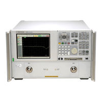
Agilent Technologies E8364B Manuals
Manuals and User Guides for Agilent Technologies E8364B. We have
5
Agilent Technologies E8364B manuals available for free PDF download: Service Manual, Installation Note, Installation And Quick Start Manual, Service Note
Agilent Technologies E8364B Service Manual (392 pages)
PNA Series Microwave Network Analyzers
Brand:
Agilent Technologies
| Category:
Measuring Instruments
| Size: 23.9 MB
Table of Contents
Service Guide E8364-90026
3
Table of Contents
5
1 Safety and Regulatory Information
11
Information in this Chapter
12
Chapter One At-A-Glance
12
Safety Symbols
13
General Safety Considerations
13
Safety Earth Ground
13
Before Applying Power
13
Servicing
14
Electrostatic Discharge Protection
16
Regulatory Information
17
Instrument Markings
17
Lithium Battery Disposal
18
2 General Product Information
19
Information in this Chapter
20
Chapter Two At-A-Glance
20
Maintenance
21
Physical Maintenance
21
Electrical Maintenance
21
Analyzer Options Available
21
Options as Upgrades
21
Option 010, Time Domain
21
Option 014, Configurable Test Set
21
Option 016, Receiver Attenuators
22
Options 040 and 041, Extended Frequency Range to 40 Ghz
22
Options 050 and 051, Extended Frequency Range to 50 Ghz
22
Option 080, Frequency Offset Mode
22
Option 081, External Reference Switch
23
Option 083, Frequency Converter Measurement Application
23
Option 099, Firmware Upgrade
23
Option 221, 2-Port Front Panel Upgrade
23
Option 897, Built-In Tests for Commercial Calibration
23
Option 898 Built-In Tests for Standards Compliant Calibration
23
Option 1CM, Rack Mount Flange Kit for Instruments Without Handles
24
Option 1CP, Rack Mount Flange Kit for Instruments with Handles
24
Option H08, Pulse Measurement Capability
24
Option H11, if Access
24
Option UNL, Source Attenuators and Bias Tees
24
Analyzer Upgrades Available
25
Analyzer Accessories Available
26
CD-RW Drive
26
USB Hub
26
Required Service Test Equipment
27
Agilent Support, Services, and Assistance
30
Service and Support Options
30
Calibration Options
30
Contacting Agilent
31
Shipping Your Analyzer to Agilent for Service or Repair
31
3 Tests and Adjustments
33
Information in this Chapter
34
Chapter Three At-A-Glance
34
Before You Begin
36
Verify the Operating Environment
36
Protect against Electrostatic Discharge (ESD)
36
Allow the Analyzer to Warm up
36
Review the Principles of Connector Care
37
About System Verification and Performance Tests
38
System Specifications
38
Instrument Specifications
38
System Verification Procedure
39
Performance Tests
39
Certificate of Calibration
39
ANSI/NCSL Z540-1-1994 Verification
41
Non-ANSI/NCSL Z540-1-1994 Verification
42
Preliminary Checks
43
The Operator's Check
43
The Test Port Cable Checks
45
System Verification
52
What the System Verification Verifies
52
Measurement Uncertainty
53
Measurement Traceability
54
Performing System Verification
55
Option H11, if Access, Operation Verification
62
Performance Tests (Agilent N7840A Software Package)
63
Source Power Accuracy Test
63
Source Maximum Power Output Test
64
Source Power Linearity Test
64
Frequency Accuracy Test
65
Trace Noise Test
65
Receiver Compression Test
66
Noise Floor Test
67
Calibration Coefficient Test
68
System Crosstalk Test
69
Dynamic Accuracy Test
70
Adjustments
72
10 Mhz Frequency Reference Adjustment
73
3.8 Ghz PMYO Frequency Adjustment
74
LO Power Adjustment
75
LO Offset Adjustment
77
Source Calibration Adjustment
79
Phase Lock if Gain Adjustment
80
Receiver Calibration Adjustment
81
4 Troubleshooting
83
Information in this Chapter
84
Chapter Four At-A-Glance
84
Protect against Electrostatic Discharge (ESD)
85
Assembly Replacement Sequence
85
Getting Started with Troubleshooting
86
Check the Basics
86
Troubleshooting Organization
87
Power up Troubleshooting
88
Power Supply Check
89
Troubleshooting LCD Display Problems
95
Front Panel Troubleshooting
99
A1 Front Panel Keypad and RPG Test
99
A2 Display Test
101
A3 Front Panel Interface Board
102
Rear Panel Troubleshooting
104
Checking the USB Ports
104
Checking the SERIAL (RS-232), PARALLEL (1284-C), or VGA Port
105
Checking the GPIB Port
105
LAN Troubleshooting
107
Measurement System Troubleshooting
111
Before You Begin-Consider: Where Do You See a Problem
111
Verifying the A, B, R1, and R2 Traces (Standard S-Parameter Mode)
113
Where to Begin Troubleshooting
114
Checking the Source Group
117
Checking the Signal Separation Group
130
Checking the Receiver Group
134
Checking the Frequency Offset Group (Option 080)
136
Instrument Block Diagrams
142
E8362B Overall Block Diagram, no Options
142
E8362B Overall Block Diagram, All Options
144
E8363B and E8364B Overall Block Diagram, no Options
146
E8363B and E8364B Overall Block Diagram, All Options
148
5 Theory of Operation
151
Information in this Chapter
152
Chapter Five At-A-Glance
152
Network Analyzer System Operation
153
Functional Groups of the Network Analyzer
153
Source Group Operation
156
Band Modes
156
A8 Fractional-N Synthesizer Board
158
A17 L.O. Multiplier/Amplifier 10 (LOMA 10)
159
A18 Multiplier/Amplifier 20 (MA 20)
159
A19 Splitter
159
A20 L.O. Distribution Assembly (LODA)
159
A10 Frequency Reference Board
159
A11 Phase Lock Board
160
A12 Source 20
160
A21 Source Multiplier/Amplifier 50 (SOMA 50) (E8363B and E8364B Only)
161
A16 Test Set Motherboard
162
Signal Separation Group Operation
166
A22 Switch Splitter
166
A25 and A26 Test Port Couplers
167
A23 and A24 Detectors (E8363B and E8364B Only)
167
30-Db Fixed Attenuators (E8362B Only)
167
A36 and A37 60-Db Source Step Attenuators (Option UNL)
168
A38 and A39 Bias Tees (Option UNL)
168
A43 and A44 35-Db Receiver Step Attenuators (Option 016)
168
Option 014 Configurable Test Set
168
Receiver Group Operation
171
A27, A28, A29, and A30 Receiver First Converters (Mixers)
171
A49 if Multiplexer Board
171
A31, A32, A33, and A34 Receiver Modules
171
A6 SPAM Board (Analog Description)
173
A35 Receiver Motherboard
173
Frequency Offset Group Operation (Options 080 and 081)
174
A9 Fractional-N Synthesizer Board (Option 080)
174
A13 Frequency Offset Receiver Assembly (Option 080)
174
A45 and A46 Reference Transfer Switches (Option 081)
174
IF Access Group (Option H11)
176
A47 RF Path Coupler
176
A48 lo Path Coupler
176
A49 if Multiplexer Board
176
Rear-Panel Connections
176
Digital Processing and Digital Control Group Operation
179
Front Panel Subgroup
181
Data Acquisition and Processing Subgroup
182
Power Supply Group Operation
184
6 Replaceable Parts
185
Information in this Chapter
186
How to Use the Replaceable Parts Listings in this Chapter
186
Chapter Six At-A-Glance
186
Ordering Information
187
Assembly Replacement Sequence
188
Rebuilt-Exchange Assemblies
189
Replaceable Parts Listings
190
Front Panel Assembly, All Options
194
Top Assemblies, All Options Except 080
196
Top Cables-All, All Options Except 080
198
Top Assemblies, All Options Including 080
200
Top Cables-All, All Options Including 080
202
Bottom Assemblies, no Options
204
Bottom Semi-Rigid Cables, no Options
206
Bottom Assemblies, Option UNL
208
Bottom Semi-Rigid Cables, Option UNL
210
Bottom Assemblies, Option 014 and Options 014/080
212
Bottom Semi-Rigid Cables, Options 014 and 014/080
214
Bottom Assemblies, Options UNL/014 and UNL/014/080
216
Bottom Semi-Rigid Cables, Options UNL/014 and UNL/014/080
218
Bottom Assemblies, Options UNL/016
220
Bottom Semi-Rigid Cables, Options UNL/016
222
Bottom Assemblies, Options UNL/014/016 and UNL/014/016/080
224
Bottom Semi-Rigid Cables, Options UNL/014/016 and UNL/014/016/080
226
Bottom Assemblies, Options 014/080/081
228
Bottom Semi-Rigid Cables, Options 014/080/081
230
Bottom Assemblies, Options UNL/014/080/081
232
Bottom Semi-Rigid Cables, Options UNL/014/080/081
234
Bottom Assemblies, Options UNL/014/080/081/H11
236
Bottom Semi-Rigid Cables, Options UNL/014/080/081/H11
238
Bottom Assemblies, Options UNL/014/016/080/081
240
Bottom Semi-Rigid Cables, Options UNL/014/016/080/081
242
Bottom Assemblies, Options UNL/014/016/080/081/H11
244
Bottom Semi-Rigid Cables, Options UNL/014/016/080/081/H11
246
Bottom Flexible Cables, All Options
248
Bottom Ribbon Cables and Wrapped-Wire, All Options
250
Top Hardware, All Options
252
Bottom Hardware, All Options
254
Internal Hardware and Parts, All Options
256
External Hardware and Parts, All Options
258
Rear Panel Assembly, All Options
260
Hard Disk Drive Assembly
262
Miscellaneous Part Numbers
264
7 Repair and Replacement Procedures
269
Information in this Chapter
270
Chapter Seven At-A-Glance
270
Before Starting the Removal and Replacement Procedures
271
Personal Safety Warnings
271
Electrostatic Discharge (ESD) Protection
271
Assembly Replacement Sequence
271
Removal and Replacement Procedures
272
Removing the Covers
274
Raising and Removing the Receiver Deck
276
Removing and Replacing the Front Panel Assembly
278
Removing and Replacing Front Panel Subassemblies
280
Removing and Replacing the Display Inverter Board and the Display Lamp
282
Removing and Replacing the A4 Power Supply Assembly
284
Removing and Replacing the A6, A8, A9, and A10 Boards
286
Removing and Replacing the A11 Phase Lock Board
288
Removing and Replacing the A12 Source 20
290
Removing and Replacing the A13 Frequency Offset Receiver Assembly
292
Removing and Replacing the A14 System Motherboard
294
Removing and Replacing the A15 CPU Board
296
Removing and Replacing the A16 Test Set Motherboard
298
Removing and Replacing the A17 LOMA 10
300
Removing and Replacing the A18 MA 20
302
Removing and Replacing the A19 Splitter
304
Removing and Replacing the A20 LODA
306
Removing and Replacing the A21 SOMA 50 (E8363B and E8364B Only)
308
Removing and Replacing the A22 Switch Splitter
310
Removing and Replacing the 30-Db Fixed Attenuators (E8362B Only)
312
Removing and Replacing the A23 and A24 Detectors (E8363B and E8364B Only)
314
Removing and Replacing the A25 and A26 Test Port Couplers
316
Bias Board
318
Multiplexer Board
320
Removing and Replacing the A35 Receiver Motherboard
322
Removing and Replacing the A36 and A37 60-Db Source Step Attenuators (Option UNL)
324
Removing and Replacing the A38 and A39 Bias Tees (Option UNL)
326
Removing and Replacing the A40 Floppy Disk Drive
328
Removing and Replacing the A41 Hard Disk Drive (HDD)
330
Removing and Replacing the A47 and A48 Couplers (Option H11)
340
Removing and Replacing the Midweb and the B1 Fan
342
Removing and Replacing the USB Hub
345
Removing and Replacing the Lithium Battery
346
Post-Repair Procedures
348
8 General Purpose Maintenance Procedures
351
Information in this Chapter
352
Chapter Eight At-A-Glance
352
Error Terms
353
Using Error Terms as a Diagnostic Tool
353
Performing Measurement Calibration
354
Using Flowgraphs to Identify Error Terms
354
Accessing Error Terms
358
Error Term Data
360
Option Enable Utility
365
Accessing the Option Enable Utility
365
Enabling or Removing Options
366
Repairing and Recovering Option Data
367
Installing or Changing a Serial Number
368
Firmware Upgrades
369
How to Check the Current Firmware Version
369
Downloading from the Internet
369
Operating System Recovery
370
Recovering from Hard Disk Drive Problems
370
Correction Constants
371
Storing Correction Constants
371
Advertisement
agilent Technologies E8364B Service Manual (372 pages)
PNA series Microwave Network Analyzers
Brand:
agilent Technologies
| Category:
Measuring Instruments
| Size: 18.73 MB
Table of Contents
Safety Notes
3
Table of Contents
5
1 Safety and Regulatory Information
13
Information in this Chapter
14
Chapter One At-A-Glance
14
Safety Symbols
15
General Safety Considerations
15
Safety Earth Ground
15
Before Applying Power
15
Servicing
16
Electrostatic Discharge Protection
17
Regulatory Information
18
Instrument Markings
18
Lithium Battery Disposal
18
Compliance with German FTZ Emissions Requirements
19
Compliance with German Noise Requirements
19
2 General Product Information
21
Information in this Chapter
22
Chapter Two At-A-Glance
22
Maintenance
23
Physical Maintenance
23
Electrical Maintenance
23
Analyzer Options, Upgrades, and Accessories
23
How to Order an Upgrade
23
Option 010, Time Domain
23
Option 014, Configurable Test Set
23
Option 016, Receiver Attenuators
24
Option 022, Extended Memory
24
Options 040 and 041, Extended Frequency Range to 40 Ghz
24
Options 050 and 051, Extended Frequency Range to 50 Ghz
24
Option 067, Extended Frequency Range to 67 Ghz
25
Option 080, Frequency Offset Mode
25
Option 081, External Reference Switch
25
Option 083, Frequency Converter Measurement Application
25
Option 099, Firmware Upgrade
25
Option UNL, Source Attenuators and Bias Tees
26
CD-RW Drive
26
USB Hub
26
Option 0BW, Printed Service Guide
26
Option 1CP, Rack Mount Flange Kit for Instruments with Handles
26
Option 1CM, Rack Mount Flange Kit for Instruments Without Handles
26
Required Service Test Equipment
27
Agilent Support, Services, and Assistance
30
Contacting Agilent
30
Service and Support Options
31
Calibration Options
31
Shipping Your Analyzer to Agilent for Service or Repair
31
3 Tests and Adjustments
33
Information in this Chapter
34
Chapter Three At-A-Glance
34
Before You Begin
36
Verify the Operating Environment
36
Protect against Electrostatic Discharge (ESD)
36
Allow the Analyzer to Warm up
36
Review the Principles of Connector Care
37
About System Verification and Performance Tests
38
System Specifications
38
Instrument Specifications
38
System Verification Procedure
39
Performance Tests
39
Certificate of Calibration
39
ANSI/NCSL Z540-1-1994 Verification
40
Non-ANSI/NCSL Z540-1-1994 Verification
41
Preliminary Checks
42
The Operator's Check
42
The Test Port Cable Checks
45
System Verification
52
What the System Verification Verifies
52
Measurement Uncertainty
53
Measurement Traceability
54
Performing System Verification
55
Performance Tests (Agilent N2721A Software Package)
62
Source Power Accuracy Test
62
Source Power Linearity Test
63
Frequency Accuracy Test
63
Trace Noise Test
64
Receiver Compression Test
64
Noise Floor Test
65
Calibration Coefficient Test
66
System Crosstalk Test
67
Dynamic Accuracy Test
67
Power Meter Accuracy Test
69
Adjustments
74
Source Calibration Adjustment
75
Receiver Calibration Adjustment
76
LO Power Adjustment
79
10 Mhz Frequency Reference Adjustment
81
3.8 Ghz PMYO Frequency Adjustment
82
4 Troubleshooting
83
Information in this Chapter
84
Chapter Four At-A-Glance
84
Protect against Electrostatic Discharge (ESD)
85
Assembly Replacement Sequence
85
Getting Started with Troubleshooting
86
Check the Basics
86
Troubleshooting Organization
87
Power up Troubleshooting
88
Power Supply Check
89
Troubleshooting LCD Display Problems
95
Front Panel Troubleshooting
99
A1 Front Panel Keypad and RPG Test
99
A2 Display Test
101
A3 Front Panel Interface Board
102
Rear Panel Troubleshooting
103
Checking the USB Ports
103
Checking the SERIAL (RS-232), PARALLEL (1284-C), or VGA Port
104
Checking the GPIB Port
104
LAN Troubleshooting
106
Measurement System Troubleshooting
110
Verifying the A, B, R1, and R2 Traces (Standard S-Parameter Mode)
111
Where to Begin Troubleshooting
112
Checking the Source Group
115
Checking the Signal Separation Group
128
Checking the Receiver Group
132
Checking the Frequency Offset Group (Option 080)
134
Instrument Block Diagrams
140
E8362B Overall Block Diagram, Includes Option UNL
141
E8363B and E8364B Overall Block Diagram, Includes Option UNL
145
5 Theory of Operation
151
Information in this Chapter
152
Chapter Five At-A-Glance
152
Network Analyzer System Operation
153
Functional Groups of the Network Analyzer
153
Source Group Operation
156
Band Modes
156
A8 Fractional-N Synthesizer Board
158
A17 L.O. Multiplier/Amplifier 10 (LOMA 10)
159
A18 Multiplier/Amplifier 20 (MA 20)
159
A19 Splitter
159
A20 L.O. Distribution Assembly (LODA)
159
A10 Frequency Reference Board
159
A11 Phase Lock Board
160
A12 Source 20
160
A21 Source Multiplier/Amplifier 50 (SOMA 50) (E8363B and E8364B Only)
161
A16 Test Set Motherboard
162
Signal Separation Group Operation
166
A22 Switch Splitter
166
A25 and A26 Test Port Couplers
167
A23 and A24 Detectors (E8363B and E8364B Only)
167
30-Db Fixed Attenuators (E8362B Only)
167
A36 and A37 60-Db Source Step Attenuators (Option UNL)
168
A38 and A39 Bias Tees (Option UNL)
168
A43 and A44 35-Db Receiver Step Attenuators (Option 016)
168
Option 014 Configurable Test Set
168
Receiver Group Operation
171
A27, A28, A29, and A30 Receiver First Converters (Mixers)
171
LO Reject/Filter Board
171
A31, A32, A33, and A34 Receiver Modules
171
A6 SPAM Board (Analog Description)
173
A35 Receiver Motherboard
173
Frequency Offset Group Operation (Option 080)
174
A9 Fractional-N Synthesizer Board
174
A13 Frequency Offset Receiver Assembly
174
A45 and A46 Reference Transfer Switches (Option 081)
174
Digital Processing and Digital Control Group Operation
176
Front Panel Subgroup
178
Data Acquisition and Processing Subgroup
179
Power Supply Group Operation
181
6 Replaceable Parts
183
Information in this Chapter
184
Chapter Six At-A-Glance
184
Ordering Information
185
Assembly Replacement Sequence
186
Rebuilt-Exchange Assemblies
187
Replaceable Parts Listings
188
Front Panel Assembly, All Options
192
Top Assemblies and Hardware, All Options Except 080
194
Top Cables, All Options Except 080
196
Top Assemblies and Hardware, All Options Including 080
198
Top Cables, All Options Including 080
200
Bottom Assemblies, no Options
202
Bottom RF Cables, no Options
204
Bottom Flexible Cables, no Options
206
Bottom Ribbon Cables and Wrapped-Wire, no Options
208
Bottom Hardware, no Options
210
Parts Included with Option UNL
212
Parts Included with Option 014 (with or W/O Option 080)
214
Parts Included with Option UNL, 016
216
Parts Included with Option UNL, 014 (with or W/O Option 080)
218
Parts Included with Option UNL, 014 (with or W/O Option 080) (Continued)
219
Parts Included with Option UNL, 014, 016 (with or W/O Option 080)
221
Parts Included with Option UNL, 014, 016 (with or W/O Option 080) (Continued)
222
Parts Included with Option 014, 080, 081
224
Parts Included with Option 014, 080, 081 (Continued)
225
Parts Included with Option UNL, 014, 080, 081
227
Parts Included with Option UNL, 014, 080, 081 (Continued)
228
Parts Included with Option UNL, 014, 016, 080, 081
230
Parts Included with Option UNL, 014, 016, 080, 081 (Continued)
231
Rear Panel Assembly, All Options
233
Internal Hardware and Parts, All Options
234
External Hardware and Parts, All Options
236
Hard Disk Drive Assembly
238
Miscellaneous Part Numbers
239
Miscellaneous Part Numbers (Continued)
241
7 Repair and Replacement Procedures
243
Information in this Chapter
244
Chapter Seven At-A-Glance
244
Before Starting the Removal and Replacement Procedures
245
Personal Safety Warnings
245
Electrostatic Discharge (ESD) Protection
245
Assembly Replacement Sequence
245
Removal and Replacement Procedures
246
Removing the Covers
248
Raising and Removing the Receiver Deck
250
Removing and Replacing the Front Panel Assembly
252
Removing and Replacing Front Panel Subassemblies
254
Removing and Replacing the Display Inverter Board and the Display Lamp
256
Removing and Replacing the A4 Power Supply Assembly
258
Removing and Replacing the A6, A8, A9, and A10 Boards
260
Removing and Replacing the A11 Phase Lock Board
262
Removing and Replacing the A12 Source 20
264
Removing and Replacing the A13 Frequency Offset Receiver Assembly
266
Removing and Replacing the A14 System Motherboard
268
Removing and Replacing the A15 CPU Board
270
Removing and Replacing the A16 Test Set Motherboard
272
Removing and Replacing the A17 LOMA 10
274
Removing and Replacing the A18 MA 20
276
Removing and Replacing the A19 Splitter
278
Removing and Replacing the A20 LODA
280
Removing and Replacing the A21 SOMA 50 (E8363B and E8364B Only)
282
Removing and Replacing the A22 Switch Splitter
284
Removing and Replacing the 30-Db Fixed Attenuators (E8362B Only)
286
Removing and Replacing the A23 and A24 Detectors (E8363B and E8364B Only)
288
Removing and Replacing the A25 and A26 Test Port Couplers
290
Removing and Replacing the A27, A28, A29, and A30 First Converters (Mixers) and Mixer Bias Board
292
Removing and Replacing the A31, A32, A33, and A34 Receiver Modules and lo Reject Filter Board
294
Removing and Replacing the A35 Receiver Motherboard
296
Removing and Replacing the A36 and A37 60-Db Source Step Attenuators (Option UNL)
298
Removing and Replacing the A38 and A39 Bias Tees (Option UNL)
300
Removing and Replacing the A40 Floppy Disk Drive
302
Removing and Replacing the A41 Hard Disk Drive
304
Removing and Replacing the Midweb and the B1 Fan
314
Removing and Replacing the USB Hub
317
Post-Repair Procedures
318
A Error Terms
321
500 D Operating System Recovery
322
Information in this Appendix
322
Appendix D At-A-Glance
322
Using Error Terms as a Diagnostic Tool
323
Preventive Maintenance
323
Troubleshooting
323
Performing Measurement Calibration
324
Using Flowgraphs to Identify Error Terms
324
Accessing Error Terms
326
Manual Access to Error Terms
326
Programmatic Access to Error Terms
327
Error Term Data
328
If Error Terms Seem Worse than Expected
329
Directivity (EDF and EDR
330
Source Match (ESF and ESR
331
Load Match (ELF and ELR
332
Reflection Tracking (ERF and ERR
333
Transmission Tracking (ETF and ETR
334
Isolation (EXF and EXR
335
Appendix A At-A-Glance
322
B Option Enable Utility
337
Information in this Appendix
338
Appendix B At-A-Glance
338
Accessing the Option Enable Utility
339
Enabling or Removing Options
340
Repairing and Recovering Option Data
341
Recovery of Data after Repair
341
Recovery of Data if Option or Model Numbers Are Incorrect
341
Installing or Changing a Serial Number
342
C Firmware Upgrades
343
Information in this Appendix
344
Appendix C At-A-Glance
344
Downloading from the Internet
344
How to Check the Current Firmware Version
344
Downloading Using Option 099, Firmware Upgrade
345
Installation Requirements
345
Downloading from a USB CD Drive Connected to the Analyzer
345
Downloading from a Shared CD Drive over the LAN
345
Downloading over the LAN
346
Information in this Appendix
348
Overview
349
System Recovery Procedure
350
If the Operating System Does Not Boot from the Hard Disk Drive
351
If the Operating System Does Not Boot from the Floppy Disk Drive
352
Agilent Technologies E8364B Installation And Quick Start Manual (24 pages)
Network Analyzers
Brand:
Agilent Technologies
| Category:
Measuring Instruments
| Size: 0.49 MB
Table of Contents
Table of Contents
4
1 Installing Your Analyzer
5
STEP 1. Check the Shipment
5
STEP 2. Meet Electrical and Environmental Requirements
8
STEP 3. Install the Analyzer on a Bench Top or in an Equipment Rack
9
To Install on a Bench Top
9
To Install in an Equipment Rack
9
STEP 4. Connect the Accessories
10
STEP 5. Install Ferrite Cores
11
STEP 6. Start up the Analyzer
12
STEP 7. Perform Administrative Tasks
13
STEP 8. Run the Operator's Check
14
STEP 9. Turn off the Analyzer
14
To Hibernate the Analyzer
14
To Shut down the Analyzer
15
2 Getting Help with Your Analyzer
17
Contacting Agilent Technologies
17
Help System
17
PNA on the Internet
18
Product Overview
18
3 Safety and Regulatory Information
19
Maintenance
19
Shipment for Service
19
Safety Symbols
19
General Safety Considerations
20
Safety Earth Ground
20
Before Applying Power
20
Servicing
21
Regulatory Information
21
Instructions for Use
21
Instrument Markings
22
Declaration of Conformity
23
Compliance with German Noise Requirements
24
Warranty
24
Advertisement
Agilent Technologies E8364B Installation Note (24 pages)
Reference Mixer Transfer Switch Upgrade Kit, Microwave Network Analyzers
Brand:
Agilent Technologies
| Category:
Measuring Instruments
| Size: 2.19 MB
Table of Contents
Warranty Statement
2
Dfars/Restricted Rights Notice
2
Safety Notes
2
Contacting Agilent
3
Step 2. Remove the Front Panel Assembly
8
Agilent Technologies E8364B Service Note (4 pages)
PNA Microwave Network Analyzers
Brand:
Agilent Technologies
| Category:
Measuring Instruments
| Size: 0.23 MB
Advertisement
Related Products
Agilent Technologies E8364BU/CU-068
Agilent Technologies E8364BPNA Series
Agilent Technologies E8364BU-068
Agilent Technologies E8364BU-014
Agilent Technologies E8364C
Agilent Technologies E8364A
Agilent Technologies E8364CU-068
Agilent Technologies E8364CU-014
Agilent Technologies E8364-90019
Agilent Technologies E8364-60103
Agilent Technologies Categories
Measuring Instruments
Laboratory Equipment
Test Equipment
Water Pump
Power Supply
More Agilent Technologies Manuals
Login
Sign In
OR
Sign in with Facebook
Sign in with Google
Upload manual
Upload from disk
Upload from URL