Sign In
Upload
Manuals
Brands
Agilent Technologies Manuals
Inverter
E8257D
Agilent Technologies E8257D Manuals
Manuals and User Guides for Agilent Technologies E8257D. We have
5
Agilent Technologies E8257D manuals available for free PDF download: Programming Manual, User Manual, Installation Manual, User's And Service Manual, Installation Note
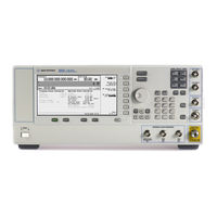
Agilent Technologies E8257D User Manual (318 pages)
PSG Signal Generators
Brand:
Agilent Technologies
| Category:
Inverter
| Size: 3.85 MB
Table of Contents
Table of Contents
3
Signal Generator Overview
15
Signal Generator Models and Features
15
E8257D PSG Analog Signal Generator Features
16
E8267D PSG Vector Signal Generator Features
17
E8663D PSG Analog Signal Generator Features
18
Options
20
Firmware Upgrades
20
To Upgrade Firmware
20
Modes of Operation
21
Continuous Wave
21
Swept Signal
21
Analog Modulation
22
Digital Modulation
22
Front Panel
23
Display
24
Softkeys
24
Knob
24
Amplitude
24
Frequency
24
Save
24
Recall
24
Trigger
25
Menus
25
Help
25
Ext 1 Input
25
Ext 2 Input
26
Lf Output
26
Mod On/Off
26
Alc Input
26
RF On/Off
26
Numeric Keypad
26
Rf Output
27
Sync out
27
Video out
27
Incr Set
27
Gate/ Pulse/ Trigger Input
27
Arrow Keys
27
Hold
27
Return
28
Contrast Decrease
28
Contrast Increase
28
Local
28
Preset
28
Line Power LED
28
Line
28
Standby LED
28
Symbol Sync
28
Data Clock
29
Data
29
Q Input
29
I Input
29
Front Panel Display
30
Active Entry Area
31
Frequency Area
31
Annunciators
31
Digital Modulation Annunciators
33
Amplitude Area
33
Error Message Area
33
Text Area
33
Softkey Label Area
33
Rear Panel
34
Event 1
38
Event 2
38
Pattern Trig in
38
Burst Gate in
38
Auxiliary I/O
39
Digital Bus
40
Q out
40
I out
40
Wideband I Inputs
40
I-Bar out
40
Wideband Q Inputs
41
COH CARRIER (Serial Prefixes >=US4646/MY4646)
41
Ghz REF out (Serial Prefixes >=US4646/MY4646)
41
Q-Bar out
41
AC Power Receptacle
42
Gpib
42
Mhz EFC
42
ALC HOLD (Serial Prefixes >=US4722/MY4722)
42
Auxiliary Interface
43
Mhz in
43
Lan
43
Mhz out
44
Stop Sweep In/Out
44
Baseband Gen Clk in
44
Z-Axis Blank/Mkrs
44
Sweep out
44
Trigger out
44
Trigger in
45
Source Settled
45
Source Module Interface
45
Rf out
46
Ext 1
46
Ext 2
46
Pulse Sync out
47
Pulse Video out
47
Pulse/Trig Gate Input
47
Alc Input
47
Data Clock
47
I in
47
Symbol Sync
48
Q in
48
Data
48
Lf out
48
Flash Drive (Serial Prefixes >=US4829/SG4829/MY4829 (E8267D) and >=US4928/SG4928/MY4928 (E8257D))
49
Basic Operation
51
Using Table Editors
52
Table Editor Softkeys
53
Modifying Table Items in the Data Fields
53
Using the User-Defined RF Output Power Limit (Option 1EA, 1EU, or 521 Only)
54
Selecting a User-Defined RF Output Power Limit
54
Using the User-Defined RF Output Power Limit (Option 1EU, or 521 Only)
54
Configuring the RF Output
56
Configuring a Continuous Wave RF Output
56
Configuring a Swept RF Output
59
Using Ramp Sweep (Option 007)
63
Extending the Frequency Range
73
Modulating a Signal
73
Turning on a Modulation Format
73
Applying a Modulation Format to the RF Output
74
Using Data Storage Functions
75
Using the Memory Catalog
75
Using the Instrument State Registers
77
Using Security Functions
79
Understanding PSG Memory Types
79
Removing Sensitive Data from PSG Memory
84
Using the Secure Display
87
Enabling Options
88
Enabling a Software Option
88
Using the Web Server
89
Activating the Web Server
89
Basic Digital Operation
93
Custom Modulation
93
Custom Arb Waveform Generator
94
Custom Real Time I/Q Baseband
94
Arbitrary (ARB) Waveform File Headers
94
Creating a File Header for a Modulation Format Waveform
95
Modifying Header Information in a Modulation Format
96
Storing Header Information for a Dual ARB Player Waveform Sequence
101
Modifying and Viewing Header Information in the Dual ARB Player
101
Playing a Waveform File that Contains a Header
104
Using the Dual ARB Waveform Player
105
Accessing the Dual ARB Player
105
Creating Waveform Segments
106
Building and Storing a Waveform Sequence
107
Playing a Waveform
108
Editing a Waveform Sequence
108
Adding Real-Time Noise to a Dual ARB Waveform (E8267D with Option 403)
109
Storing and Loading Waveform Segments
109
Renaming a Waveform Segment
110
Using Waveform Markers
110
Waveform Marker Concepts
111
Accessing Marker Utilities
115
Viewing Waveform Segment Markers
116
Clearing Marker Points from a Waveform Segment
117
Setting Marker Points in a Waveform Segment
118
Controlling Markers in a Waveform Sequence (Dual ARB Only)
120
Viewing a Marker Pulse
122
Using the RF Blanking Marker Function
123
Setting Marker Polarity
125
Triggering Waveforms
125
Source
126
Mode and Response
126
Accessing Trigger Utilities
127
Setting the Polarity of an External Trigger
128
Using Gated Triggering
128
Using Segment Advance Triggering
130
Using Waveform Clipping
131
How Power Peaks Develop
131
How Peaks Cause Spectral Regrowth
133
How Clipping Reduces Peak-To-Average Power
134
Configuring Circular Clipping
137
Configuring Rectangular Clipping
138
Using Waveform Scaling
139
How DAC Over-Range Errors Occur
139
How Scaling Eliminates DAC Over-Range Errors
140
Scaling a Currently Playing Waveform (Runtime Scaling)
141
Scaling a Waveform File in Volatile Memory
141
Setting the Baseband Frequency Offset
142
Optimizing Performance
143
Using the ALC
143
Selecting ALC Bandwidth
143
Optimizing Performance
144
To Select an ALC Bandwidth
144
Using External Leveling
144
To Level with Detectors and Couplers/Splitters
144
To Level with a MM-Wave Source Module
147
Creating and Applying User Flatness Correction
147
Creating a User Flatness Correction Array
149
Creating a User Flatness Correction Array with a MM-Wave Source Module
154
Using the Option 521 Detector Calibration (Option 521)
160
Running the Option 521 Detector Calibration
160
Restoring the Factory Flatness Calibration
160
Adjusting Reference Oscillator Bandwidth (Option UNR/UNX/UNY)
161
To Select the Reference Oscillator Bandwidth
161
To Restore Factory Default Settings
161
Optimizing Phase Noise and Harmonics below 3.2 Ghz (Option UNX/UNY)
161
Optimizing Phase Noise below 250 Mhz
162
Figure
162
Optimizing Harmonics below 2 Ghz
163
Caution
162
Analog Modulation
165
Analog Modulation Waveforms
165
Configuring am (Option UNT)
166
To Set the Carrier Frequency
166
To Set the RF Output Amplitude
166
To Set the am Depth and Rate
166
To Turn on Amplitude Modulation
166
Configuring FM (Option UNT)
166
To Set the RF Output Frequency
166
Analog Modulation
166
Configuring ΦM (Option UNT)
167
To Set the RF Output Frequency
167
To Set the RF Output Amplitude
167
To Activate FM
168
To Activate FM
167
To Set the FM Deviation and Rate
167
Configuring Pulse Modulation (Option UNU/UNW)
168
To Set the RF Output Frequency
168
To Set the RF Output Amplitude
168
To Set the Pulse Period, Width, and Triggering
168
To Activate Pulse Modulation
168
Triggering Simultaneous Pulses from Two Psgs Using an Internal or an External Pulse Source
169
Configuring the LF Output (Option UNT)
170
Analog Modulation Waveforms
170
To Configure the LF Output with an Internal Modulation Source
171
To Configure the LF Output with a Function Generator Source
172
Custom Arb Waveform Generator
173
Overview
173
Working with Predefined Setups (Modes)
173
Selecting a Custom ARB Setup or a Custom Digital Modulation State
173
Working with User-Defined Setups (Modes)-Custom Arb Only
174
Modifying a Single-Carrier NADC Setup
174
Customizing a Multicarrier Setup
175
Recalling a User-Defined Custom Digital Modulation State
176
Working with Filters
176
Using a Predefined FIR Filter
177
Using a User-Defined FIR Filter
178
Working with Symbol Rates
183
To Set a Symbol Rate
183
To Restore the Default Symbol Rate (Custom Real Time I/Q Only)
184
Working with Modulation Types
185
To Select a Predefined Modulation Type
185
To Use a User-Defined Modulation Type (Real Time I/Q Only)
186
Differential Wideband IQ (Option 016)
191
Single-Ended Wideband IQ (Option 015 - Discontinued)
191
Configuring Hardware
192
To Set a Delayed, Positive Polarity, External Single Trigger
192
Custom Real Time I/Q Baseband
195
Overview
195
Working with Predefined Setups (Modes)
195
Selecting a Predefined Real Time Modulation Setup
195
Deselecting a Predefined Real Time Modulation Setup
196
Working with Data Patterns
196
Using a Predefined Data Pattern
197
Using a User-Defined Data Pattern
197
Using an Externally Supplied Data Pattern
201
Working with Burst Shapes
201
Configuring the Burst Rise and Fall Parameters
202
Using User-Defined Burst Shape Curves
202
Configuring Hardware
205
To Set the External DATA CLOCK to Receive Input as Either Normal or Symbol
205
To Set the BBG DATA CLOCK to External or Internal
206
To Adjust the I/Q Scaling
206
Working with Phase Polarity
206
To Set Phase Polarity to Normal or Inverted
206
Working with Differential Data Encoding
206
Understanding Differential Encoding
207
Using Differential Encoding
211
GPS Modulation (Option 409)
215
Real Time MSGPS
216
Signal Generation Block Diagram
217
Scenario Files
218
RF Power Level Considerations
219
Generating a Real Time MSGPS Signal
222
Configuring the External Reference Clock
223
Real Time GPS
224
Real Time GPS Introduction
225
Setting up the Real Time GPS Signal
230
Configuring the External Reference Clock
231
Testing Receiver Sensitivity
233
Multitone Waveform Generator
235
Overview
235
Creating, Viewing, and Optimizing Multitone Waveforms
236
To Create a Custom Multitone Waveform
236
To View a Multitone Waveform
237
To Edit the Multitone Setup Table
238
To Minimize Carrier Feedthrough
240
To Determine Peak to Average Characteristics
241
Two-Tone Waveform Generator
245
Overview
245
Creating, Viewing, and Modifying Two-Tone Waveforms
245
To Create a Two-Tone Waveform
246
To View a Two-Tone Waveform
247
To Minimize Carrier Feedthrough
248
To Change the Alignment of a Two-Tone Waveform
249
AWGN Waveform Generator
251
Configuring the AWGN Generator
251
Arb Waveform Generator AWGN
251
Real Time I/Q Baseband AWGN
252
Peripheral Devices
253
N5102A Digital Signal Interface Module
253
Clock Timing
253
Connecting the Clock Source and the Device under Test
266
Data Types
268
Operating the N5102A Module in Output Mode
269
Operating the N5102A Module in Input Mode
278
Millimeter-Wave Source Modules
286
Millimeter- Wave Source Modules
286
Using Agilent Millimeter- Wave Source Modules
286
Using Agilent Millimeter-Wave Source Modules
286
Using Other Source Modules
290
Troubleshooting
293
RF Output Power Problems
293
No RF Output Power When Playing a Waveform File (E8267D Only)
293
RF Output Power too Low
294
The Power Supply Has Shut down
294
Signal Loss While Working with a Mixer
294
Signal Loss While Working with a Spectrum Analyzer
296
No Modulation at the RF Output
299
Sweep Problems
300
Sweep Appears to be Stalled
300
Cannot Turn off Sweep Mode
300
Incorrect List Sweep Dwell Time
300
List Sweep Information Is Missing from a Recalled Register
301
Data Storage Problems
301
Registers with Previously Stored Instrument States Are Empty
301
Saved Instrument State, but Register Is Empty or Contains Wrong State
301
Cannot Turn off Help Mode
302
Signal Generator Locks up
302
Fail-Safe Recovery Sequence
302
Error Messages
303
Error Message File
304
Error Message Format
304
Error Message Types
304
Contacting Agilent Sales and Service Offices
305
Returning a Signal Generator to Agilent Technologies
305
Advertisement
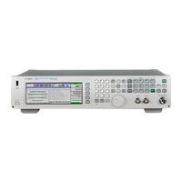
Agilent Technologies E8257D Programming Manual (366 pages)
Signal Generators
Brand:
Agilent Technologies
| Category:
Inverter
| Size: 4.68 MB
Table of Contents
Table of Contents
3
1 Getting Started with Remote Operation
12
Programming and Software/Hardware Layers
12
Interfaces
13
IO Libraries and Programming Languages
15
Agilent IO Libraries Suite
15
Windows NT and Agilent IO Libraries M (and Earlier)
16
Selecting IO Libraries for GPIB
17
Selecting IO Libraries for LAN
18
Programming Languages
19
Using the Web Browser
20
Enabling the Signal Generator Web Server
21
Preferences
26
Configuring the Display for Remote Command Setups (Agilent MXG)
27
Configuring the Display for Remote Command Setups (ESG/PSG/E8663B)
27
Getting Help (Agilent MXG)
28
Getting Help (ESG/PSG/E8663B)
28
Setting the Help Mode (ESG/PSG/E8663B)
28
Error Messages
29
Error Message File
29
Error Message Types
30
2 Using IO Interfaces
32
Using GPIB
32
Installing the GPIB Interface
32
Set up the GPIB Interface
34
Verify GPIB Functionality
35
GPIB Interface Terms
35
GPIB Programming Interface Examples
36
Before Using the GPIB Examples
36
Interface Check Using HP Basic and GPIB
36
Interface Check Using NI-488.2 and C
36
Using LAN
38
Setting up the LAN Interface
39
Setting up Private LAN
44
Verifying LAN Functionality
44
Using VXI-11
47
Using Sockets LAN
49
Using Telnet LAN
49
Using FTP
53
Using RS-232 (ESG, PSG, and E8663B Only)
55
Selecting IO Libraries for RS- 232
55
Setting up the RS-232 Interface
56
Verifying RS-232 Functionality
58
Character Format Parameters
59
If You Have Problems
59
RS-232 Programming Interface Examples
60
Before Using the Examples
60
Interface Check Using HP BASIC
60
Interface Check Using VISA and C
61
Queries Using HP Basic and RS- 232
61
Queries for RS-232 Using VISA and C
62
Using USB (Agilent MXG)
63
Selecting I/O Libraries for USB
64
Setting up the USB Interface
65
3 Programming Examples
67
Using the Programming Interface Examples
68
Programming Examples Development Environment
68
Running C++ Programs
69
Running C# Examples
70
Running Basic Examples
70
Running Java Examples
71
Running MATLAB Examples
71
Running Perl Examples
71
Using GPIB
72
Installing the GPIB Interface Card
72
GPIB Programming Interface Examples
72
Before Using the GPIB Examples
72
GPIB Function Statements (Command Messages)
73
Interface Check Using HP Basic and GPIB
76
Interface Check Using NI-488.2 and C
77
Interface Check for GPIB Using VISA and C
78
Local Lockout Using HP Basic and GPIB
79
Local Lockout Using NI-488.2 and C
81
Queries Using HP Basic and GPIB
82
Queries Using NI-488.2 and Visual C
83
Queries for GPIB Using VISA and C
85
Generating a CW Signal Using VISA and C
87
Generating an Externally Applied AC-Coupled FM Signal Using VISA and C
89
Generating an Internal FM Signal Using VISA and C
91
Generating a Step-Swept Signal Using VISA and C
93
Generating a Swept Signal Using VISA and Visual C
94
Saving and Recalling States Using VISA and C
98
Reading the Data Questionable Status Register Using VISA and C
100
Reading the Service Request Interrupt (SRQ) Using VISA and C
104
Using 8757D Pass-Thru Commands (PSG with Option 007 Only)
108
LAN Programming Interface Examples
111
VXI-11 Programming
111
VXI-11 Programming Using SICL and C
112
VXI-11 Programming Using VISA and C
113
Sockets LAN Programming and C
115
Queries for Lan Using Sockets
117
Sockets LAN Programming Using Java
138
Sockets LAN Programming Using PERL
140
Programming Interface Examples (ESG/PSG/E8663B Only)
141
Before Using the Examples
141
Interface Check Using HP BASIC
141
Interface Check Using VISA and C
142
Queries Using HP Basic and RS- 232
144
Queries for RS-232 Using VISA and C
145
4 Programming the Status Register System
147
Overview
148
Overall Status Byte Register Systems
149
Status Register Bit Values
158
Example: Enable a Register
158
Example: Query a Register
158
Accessing Status Register Information
159
Determining What to Monitor
159
Deciding How to Monitor
159
Status Register SCPI Commands
161
Status Byte Group
164
Status Byte Register
165
Service Request Enable Register
165
Status Groups
166
Standard Event Status Group
167
Standard Operation Status Group
169
Baseband Operation Status Group
172
Data Questionable Status Group
175
Data Questionable Power Status Group
178
Data Questionable Frequency Status Group
181
Data Questionable Modulation Status Group
184
Data Questionable Calibration Status Group
187
Data Questionable BERT Status Group
190
5 Creating and Downloading Waveform Files
193
5 Creating and Downloading Waveform Files
194
Overview of Downloading and Extracting Waveform Files
194
Waveform Data Requirements
195
Understanding Waveform Data
195
Bits and Bytes
195
LSB and MSB (Bit Order)
196
Little Endian and Big Endian (Byte Order)
196
Byte Swapping
198
DAC Input Values
198
2'S Complement Data Format
201
I and Q Interleaving
201
Waveform Structure
203
File Header
203
Marker File
203
I/Q File
204
Waveform
205
Waveform Phase Continuity
205
Phase Discontinuity, Distortion, and Spectral Regrowth
205
Avoiding Phase Discontinuities
206
Waveform Memory
208
Memory Allocation
210
Memory Size
212
Commands for Downloading and Extracting Waveform Data
214
Waveform Data Encryption
214
File Transfer Methods
215
SCPI Command Line Structure
215
Commands and File Paths for Downloading and Extracting Waveform Data
216
FTP Procedures
220
Creating Waveform Data
222
Code Algorithm
223
Downloading Waveform Data
228
Using Simulation Software
229
Using Advanced Programming Languages
231
Loading, Playing, and Verifying a Downloaded Waveform
234
Loading a File from Non-Volatile Memory
234
Playing the Waveform
235
Verifying the Waveform
236
Building and Playing Waveform Sequences
236
Using the Download Utilities
237
Downloading E443Xb Signal Generator Files
238
E443Xb Data Format
238
Storage Locations for E443Xb ARB Files
239
SCPI Commands
241
Programming Examples
241
C++ Programming Examples
242
MATLAB Programming Examples
265
Visual Basic Programming Examples
272
HP Basic Programming Examples
277
Troubleshooting Waveform Files
286
Configuring the Pulse/Rf Blank (Agilent MXG)
287
Configuring the Pulse/Rf Blank (ESG/PSG)
287
6 Creating and Downloading User-Data Files
289
Overview
290
Signal Generator Memory
291
Memory Allocation
293
Memory Size
294
Checking Available Memory
295
User File Data (Bit/Binary) Downloads (E4438C and E8267D)
296
User File Bit Order (LSB and MSB)
298
Bit File Type Data
298
Binary File Type Data
301
User File Size
302
Determining Memory Usage for Custom and TDMA User File Data
303
Downloading User Files
306
Command for Bit File Downloads
309
Commands for Binary File Downloads
310
Selecting a Downloaded User File as the Data Source
311
Modulating and Activating the Carrier
312
Modifying User File Data
312
Understanding Framed Transmission for Real-Time TDMA
314
Real-Time Custom High Data Rates
317
Pattern RAM (PRAM) Data Downloads (E4438C and E8267D)
319
Understanding PRAM Files
320
PRAM File Size
323
SCPI Command for a List Format Download
324
SCPI Command for a Block Data Download
325
Selecting a Downloaded PRAM File as the Data Source
328
Modulating and Activating the Carrier
329
Storing a PRAM File to Non-Volatile Memory and Restoring to Volatile Memory
329
Extracting a PRAM File
329
Modifying PRAM Files
331
FIR Filter Coefficient Downloads (N5182A, E4438C and E8267D)
332
Data Requirements
332
Data Limitations
332
Downloading FIR Filter Coefficient Data
333
Selecting a Downloaded User FIR Filter as the Active Filter
333
Save and Recall Instrument State Files
335
Save and Recall SCPI Commands
335
Save and Recall Programming Example Using VISA and C
336
User Flatness Correction Downloads Using C++ and VISA
346
Data Transfer Troubleshooting (N5182A, E4438C and E8267D Only)
350
User File Download Problems
350
PRAM Download Problems
351
User FIR Filter Coefficient File Download Problems
353
Agilent Technologies E8257D Installation Manual (42 pages)
PSG Signal Generators
Brand:
Agilent Technologies
| Category:
Inverter
| Size: 0.27 MB
Table of Contents
Table of Contents
3
1 Safety Information
5
Instrument Markings
5
Warnings, Cautions, and Notes
6
General Safety Considerations
6
2 Getting Started
7
Checking the Shipment
8
Meeting Electrical and Environmental Requirements
9
Environment
9
Ventilation
9
Line Settings
10
Connecting the AC Power Cord
10
AC Power Cord Localization
11
Configuring the Display
12
Contrast and Brightness
12
Inverse Video
12
Screen Saver
12
Updating the Display During Remote Operation
13
Configuring for Remote Control
14
GPIB Interface Configuration
14
LAN Interface Configuration
14
RS-232 Interface Configuration
16
Ordering Accessories
17
Front Handles and Rack Mount Flanges
17
E8257D/67D PSG Documentation
17
Proper Usage and Cleaning
19
Cleaning Suggestions
19
Contacting Agilent Sales and Service Offices
20
Returning a Signal Generator to Agilent Technologies
21
3 Operation Verification
23
Performing a Self-Test
24
Self-Test Failure
25
Checking the Maximum Leveled Power
26
Maximum Leveled Power Check Failure
26
Checking the Output Power
29
Problems with Output Power
36
4 Regulatory Information
37
Statement of Compliance
38
Assistance
38
Certification
38
Compliance with German Noise Requirements
38
Compliance with Canadian EMC Requirements
39
Advertisement
Agilent Technologies E8257D User's And Service Manual (33 pages)
Brand:
Agilent Technologies
| Category:
Portable Generator
| Size: 1.09 MB
Table of Contents
Table of Contents
6
E8257D Option HAR
8
Description
9
Verifying the Shipment
9
Block Diagram
9
Specifications
10
Phase Noise
10
Maximum Level Output Power
10
Typical Performance
11
Phase Noise
11
Amplitude
11
Modulation
13
Frequency Modulation
13
Phase Modulation
13
Amplitude Modulation
14
Pulse Modulation
14
ALC Performance
14
Ramp Sweep
14
Operation
15
E8257D Option HAR Using the E5500 Phase Noise Measurement Subsystem
15
Service
16
Troubleshooting
16
Replaceable Parts
18
Performance Test
18
Setting up the E5500 Software
19
10 Mhz Phase Noise Test Limits
20
10 Mhz Test Procedure
20
Making the 10 Mhz Measurement
22
100 Mhz Phase Noise Test Limits
23
100 Mhz Test Procedure
23
Making the 100 Mhz Measurement
25
Appendix
26
Modifying Synthesizer Self Test Limits
26
Safety and Regulatory Information
27
Introduction
27
Cleaning the Instrument
27
Connector Care and Cleaning
27
Declaration of Conformity
27
Statement of Compliance
28
Shipping Instructions
28
Compliance with Canadian EMC Requirements
28
Compliance with German FTZ Emissions Requirements
28
Compliance with German Noise Requirements
28
General Safety Considerations
29
Safety Earth Ground
29
Before Applying Power
29
Servicing
30
Electrostatic Discharge Protection
31
Regulatory Information
32
Instrument Markings
32
Contacting Agilent Sales and Service Offices
33
Agilent Technologies E8257D Installation Note (16 pages)
Brand:
Agilent Technologies
| Category:
Signal Processors
| Size: 0.25 MB
Advertisement
Related Products
Agilent Technologies E8257D/67D
Agilent Technologies E8257C PSG
Agilent Technologies E8257D PSG
Agilent Technologies E8257C
Agilent Technologies E8257N
Agilent Technologies E8257Db
Agilent Technologies E8247C PSG CW
Agilent Technologies E8267C PSG
Agilent Technologies E8267CK-602
Agilent Technologies E8267Db
Agilent Technologies Categories
Measuring Instruments
Laboratory Equipment
Test Equipment
Water Pump
Power Supply
More Agilent Technologies Manuals
Login
Sign In
OR
Sign in with Facebook
Sign in with Google
Upload manual
Upload from disk
Upload from URL