Agilent Technologies 83623A Manuals
Manuals and User Guides for Agilent Technologies 83623A. We have 2 Agilent Technologies 83623A manuals available for free PDF download: Service Manual
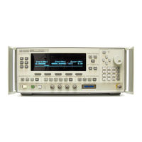
Agilent Technologies 83623A Service Manual (687 pages)
Synthesized Sweepers
Brand: Agilent Technologies
|
Category: Blower
|
Size: 15.08 MB
Table of Contents
Advertisement

Agilent Technologies 83623A Service Manual (687 pages)
Synthesized Sweepers
Brand: Agilent Technologies
|
Category: Laboratory Equipment
|
Size: 5.36 MB