
Related Manuals for Juniper EX4550


Summary of Contents for Juniper EX4550
- Page 1 EX4550 Switch Hardware Guide Modified: 2015-06-29 Copyright © 2015, Juniper Networks, Inc.
- Page 2 END USER LICENSE AGREEMENT The Juniper Networks product that is the subject of this technical documentation consists of (or is intended for use with) Juniper Networks software. Use of such software is subject to the terms and conditions of the End User License Agreement (“EULA”) posted at http://www.juniper.net/support/eula.html.
-
Page 3: Table Of Contents
EX4550 Switches Hardware Overview ........3... - Page 4 AC Power Supply in EX4550 Switches ........
- Page 5 Installing the Switch ..........147 Installing and Connecting an EX4550 Switch ......147 Mounting an EX4550 Switch .
- Page 6 Connecting Earth Ground to an EX Series Switch ..... 162 Connecting AC Power to an EX4550 Switch ......163 Connecting DC Power to an EX4550 Switch .
- Page 7 Packing an EX4550 Switch or Component for Shipping ....240 Packing an EX4550 Switch for Shipping ......240 Packing EX4550 Switch Components for Shipping .
- Page 8 Nonregulatory Environmental Standards ......307 Compliance Statements for Acoustic Noise for EX Series Switches ..308 viii Copyright © 2015, Juniper Networks, Inc.
- Page 9 Figure 3: Rear Panel of an EX4550 Switch ....... .
- Page 10 EX4550 Switch Chassis ........
- Page 11 Figure 79: Location of the Serial Number ID Label on a 10GBASE-T Expansion Module Used in an EX4550 Switch ....... . 237 Figure 80: Location of the Serial Number ID Label on a Virtual Chassis Module Used in an EX4550 Switch .
- Page 12 Electrical Safety Guidelines and Warnings ......285 Figure 81: Placing a Component into an Antistatic Bag ....288 Copyright © 2015, Juniper Networks, Inc.
- Page 13 Cooling System and Airflow ........35 Table 17: Fan Modules in EX4550 Switches ......36 Table 18: Airflow Direction in EX4550 Switches .
- Page 14 Table 49: Optical interface Support and Copper Interface Support for 1-gigabit SFP Transceivers in EX4550 Switches ....... 95 Table 50: Optical interface Support for 10-gigabit SFP+ Transceivers in EX4550 Switches .
- Page 15 Table 70: Virtual Chassis Components to Consider When Planning an EX4200, EX4500, and EX4550 Virtual Chassis ......138 Table 71: Cabling Requirements for a Virtual Chassis .
- Page 16 EX4550 Switch Hardware Guide Copyright © 2015, Juniper Networks, Inc.
-
Page 17: About The Documentation
® To obtain the most current version of all Juniper Networks technical documentation, see the product documentation page on the Juniper Networks website at http://www.juniper.net/techpubs/ If the information in the latest release notes differs from the information in the documentation, follow the product Release Notes. -
Page 18: Table 1: Notice Icons
RFC 1997, BGP Communities Attribute Italic text like this Represents variables (options for which Configure the machine’s domain name: you substitute a value) in commands or [edit] configuration statements. root@# set system domain-name domain-name xviii Copyright © 2015, Juniper Networks, Inc. -
Page 19: Documentation Feedback
We encourage you to provide feedback, comments, and suggestions so that we can improve the documentation. You can provide feedback by using either of the following methods: Online feedback rating system—On any page at the Juniper Networks Technical Documentation site at , simply click the http://www.juniper.net/techpubs/index.html... -
Page 20: Requesting Technical Support
7 days a week, 365 days a year. Self-Help Online Tools and Resources For quick and easy problem resolution, Juniper Networks has designed an online self-service portal called the Customer Support Center (CSC) that provides you with the following features: Find CSC offerings: http://www.juniper.net/customers/support/... - Page 21 About the Documentation For international or direct-dial options in countries without toll-free numbers, see http://www.juniper.net/support/requesting-support.html Copyright © 2015, Juniper Networks, Inc.
- Page 22 EX4550 Switch Hardware Guide xxii Copyright © 2015, Juniper Networks, Inc.
-
Page 23: Overview
PART 1 Overview System Overview on page 3 Chassis Components and Descriptions on page 17 Cooling System and Airflow on page 35 Power Supplies on page 41 Viewing System Information on page 49 Copyright © 2015, Juniper Networks, Inc. - Page 24 EX4550 Switch Hardware Guide Copyright © 2015, Juniper Networks, Inc.
-
Page 25: System Overview
Networks EX4200 Ethernet Switches or Juniper Networks EX4500 Ethernet Switches or both, in a total of up to 10 members. You can expand the number of ports on an EX4550 switch by installing up to two optional expansion modules in the module slots on either side of the chassis. -
Page 26: Software
Layer 3 switching, routing, and security services. The same Junos OS code base that runs on EX Series switches also runs on all Juniper Networks M Series, MX Series, and T Series routers, and SRX Series Services Gateways. For information about installing software... -
Page 27: Optional Modules
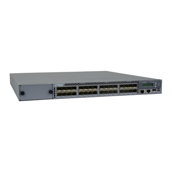
EX4550-32T switch. Figure 2: Front Panel of an EX4550-32T Switch Figure 3 on page 5 shows the rear panel of an EX4550 switch with power supplies and fan modules installed. Figure 3: Rear Panel of an EX4550 Switch... -
Page 28: Virtual Chassis
Virtual Chassis Hardware Configurations” on page 135. You can use the following ports to connect an EX4550 switch in a Virtual Chassis: Dedicated VCPs on the Virtual Chassis module installed in the switch SFP+ network ports and SFP+ expansion module ports configured as VCPs... -
Page 29: Power Supplies
EX4550-32F-S switches are not shipped with pre-installed power supplies; you must order them separately. You can install a second AC or DC power supply in the EX4550 switches. See “AC Power Supply in EX4550 Switches”... -
Page 30: Components On The Ex4550 Switch
EX4550 Switch Hardware Guide All the EX4550 switchmodels, except the EX4550-32F-S switches are shipped with three fan modules pre-installed in the rear panel of the switches. EX4550-32F-S switches are not shipped with pre-installed fan modules; you must order them separately. -
Page 31: Ex4550 Switch Models
Ethernet network ports Figure 6 on page 9 shows the components on the rear panel of an EX4550 switch (with the module slot cover panel, an AC power supply, and three fan modules installed). Figure 6: Components on the Rear Panel of an EX4550 Switch 1—... -
Page 32: Table 4: Ex4550 Switch Model Number, Shipped Components, And Supported
EX4550 Switch Hardware Guide Table 4: EX4550 Switch Model Number, Shipped Components, and Supported Junos OS Release First Junos Number and Model Number Types of Ports Direction of Airflow Fan Modules Power Supply Release EX4550-32F-AFI 32-port 10-Gigabit Back-to-front—air Three fan One AC power 12.2R1... - Page 33 Chapter 1: System Overview Table 4: EX4550 Switch Model Number, Shipped Components, and Supported Junos OS Release (continued) First Junos Number and Model Number Types of Ports Direction of Airflow Fan Modules Power Supply Release EX4550-32T-AFI 32-port 10-Gigabit Back-to-front—air Three fan One AC power 12.2R4...
-
Page 34: Identifying Ex4550 Switch Models
EX4550 Switch Hardware Guide Identifying EX4550 Switch Models Purpose Identify the model number of your EX4550 switch. Action Check the value of the FRU Model Number field in the Routing Engine section in the output of the show chassis hardware extensive CLI command. -
Page 35: Ex4550 Switch Hardware And Cli Terminology Mapping
EX4550 Switch Models on page 9 Documentation EX4550 Switch Hardware and CLI Terminology Mapping This topic describes the hardware terms used in EX4550 switch documentation and the corresponding terms used in the Junos OS CLI. See Table 5 on page... -
Page 36: Table 8: Expansion Modules In Ex4550 Switches
EX4550 Switch Hardware Guide Table 5: CLI Equivalents of Terms Used in the Documentation for EX4550 Switches (continued) Hardware Description Item (CLI) (CLI) Value (CLI) Item in Documentation Additional Information PIC (n) Abbreviated n is a value in the range 0... - Page 37 Chapter 1: System Overview Table 5: CLI Equivalents of Terms Used in the Documentation for EX4550 Switches (continued) Hardware Description Item (CLI) (CLI) Value (CLI) Item in Documentation Additional Information JPSU-650W AC and DC power supplies DC Power Supply in...
- Page 38 EX4550 Switch Hardware Guide Copyright © 2015, Juniper Networks, Inc.
-
Page 39: Chassis Components And Descriptions
Chassis Status LEDs in EX4550 Switches on page 28 Management Port LEDs in EX4550 Switches on page 29 Network Port and Expansion Module Port LEDs in EX4550 Switches on page 30 Chassis Physical Specifications for EX4550 Switches The EX4550 switch chassis is a rigid sheet-metal structure that houses all components of the switch. -
Page 40: Field-Replaceable Units In Ex4550 Switches
EX4550 Switch Hardware Guide You can mount an EX4550 switch on a standard 19-in. two-post rack. You can also mount the switch on a standard 19-in. four-post rack or in a standard 19-in. enclosed cabinet. Related Rack Requirements for EX4550 Switches on page 79... -
Page 41: Lcd Panel In Ex4550 Switches
Chapter 2: Chassis Components and Descriptions LCD Panel in EX4550 Switches The LCD panel of the EX4550 switch shows two lines of text, each that can contain a maximum of 16 characters. The LCD panel displays a variety of information about the switch and also provides a menu to perform basic operations such as initial setup and reboot. -
Page 42: Lcd Panel Menus
EX4550 Switch Hardware Guide In an EX4550 switch that is a member of a Virtual Chassis, the first line of the LCD panel always displays: The slot number (the member ID for the Virtual Chassis member) Role of the switch in the Virtual Chassis (... -
Page 43: Chassis Components And Descriptions
ADM (administrative status) DPX (duplex) SPD (speed) “Network Port and Expansion Module Port LEDs in EX4550 Switches” on page 30 for information about the Status LED modes. Press Menu to exit the Idle menu and go to the Status menu. - Page 44 EX4550 Switch Hardware Guide Table 7: LCD Panel Menu Options in EX4550 Switches (continued) Menu Label Description MAINT The Maintenance menu has the following options to configure and troubleshoot the switch: (Maintenance SYSTEM HALT?—Choose one of the following: Menu) Press Enter to halt the switch. Press Enter again to confirm the halt.
-
Page 45: Expansion Modules In Ex4550 Switches
You must order them separately. You can install up to two expansion modules in an EX4550 switch—one in each of the module slots on the front panel and the rear panel of the switch. By installing an expansion module, you add more ports to your switch, thereby increasing the port density of the switch. -
Page 46: Figure 8: 8-Port Sfp+ Expansion Module
Each expansion module has an LED on the faceplate (labeled ). It indicates the status of the expansion module. Figure 11 on page 25 shows the location of LEDs on the SFP+ expansion module. Copyright © 2015, Juniper Networks, Inc. -
Page 47: Figure 11: Leds On An Sfp+ Expansion Module
Figure 13: LEDs on a QSFP+ Expansion Module Link Status Link Status 1— Status LED of the expansion module 3— Port’s Status LED 2—Port’s Link/Activity LED Table 9 on page 26 describes the Status LED on the expansion modules. Copyright © 2015, Juniper Networks, Inc. -
Page 48: Virtual Chassis Module In Ex4550 Switches
EX4550 switch chassis. The Virtual Chassis module has two dedicated Virtual Chassis ports (VCPs), using which you can interconnect the EX4550 switch to an EX4200, EX4500, or EX4550 switch in a Virtual Chassis configuration. Figure 14 on page 26 shows the Virtual Chassis module. -
Page 49: Figure 15: Virtual Chassis Module Led
EX4500 switches through SFP+ expansion module ports or SFP+ network ports configured as VCPs to form a Virtual Chassis. You can also configure 10GBASE-T network ports, 10GBASE-T expansion module ports, or QSFP+ expansion module ports as VCPs to interconnect EX4550 switches in a Virtual Chassis. NOTE:... -
Page 50: Chassis Status Leds In Ex4550 Switches
EX4550 Switches Hardware Overview on page 3 Chassis Status LEDs in EX4550 Switches The front panel of an EX4550 switch has three chassis status LEDs (labeled ) on the far right side of the panel, next to the Menu and Enter buttons (see Figure 16 on page 28). -
Page 51: Management Port Leds In Ex4550 Switches
EX4550 Switches Hardware Overview on page 3 Management Port LEDs in EX4550 Switches The management port, which is on the front panel of an EX4550 switch, has two LEDs that indicate link activity and status of the management port (see Figure 17 on page 29). -
Page 52: Network Port And Expansion Module Port Leds In Ex4550 Switches
EX4550 Switch Hardware Guide Table 12: Link/Activity LED on the Management Port on an EX4550 Switch Color State and Description Link/Activity Green Blinking—The port and the link are active, and there is link activity. On steadily—The port and the link are active, but there is no link activity. -
Page 53: Figure 19: 10Gbase-T Ethernet Network Port And 10Gbase-T Expansion Module
LED that indicate the link activity of the port. Each LED is shaped to point toward the port for which it displays the link activity. Figure 20 on page 31 shows the LEDs on the QSFP+ expansion module ports of an EX4550 switch. Figure 20: QSFP+ Expansion Module Port LEDs Each QSFP+ expansion module port has two LEDs that indicate link activity and status of the expansion module ports. -
Page 54: Table 15: Status Led On Sfp+ Network Ports And Expansion Module Ports
Status LED on SFP+ network ports and SFP+ expansion module ports in EX4550 switches. From the Idle menu of the LCD panel, use the Enter button on the LCD panel to toggle between the ADM, DPX, and SPD indicators. - Page 55 Chapter 2: Chassis Components and Descriptions Related Expansion Modules in EX4550 Switches on page 23 Documentation EX4550 Switches Hardware Overview on page 3 Copyright © 2015, Juniper Networks, Inc.
- Page 56 EX4550 Switch Hardware Guide Copyright © 2015, Juniper Networks, Inc.
-
Page 57: Cooling System And Airflow
Cooling System and Airflow in an EX4550 Switch on page 35 Cooling System and Airflow in an EX4550 Switch The cooling system in an EX4550 switch consists of three fan modules and a single fan in each power supply. EX4550 switches provide back-to-front airflow (air comes in from the back of the switch) or front-to-back (air exhausts through the back of the switch) airflow depending on the fan modules and power supplies installed in the switch. -
Page 58: Airflow Direction In Ex4550 Switches
EX4550 switches except the EX4550-32F-S switches have the fan modules and power supplies preinstalled on the rear panel of the switches. Power supplies and fan modules for the EX4550-32F-S switch are not shipped by default; you must order them separately. -
Page 59: Back-To-Front Airflow
) with different airflow labels in the same chassis. Back-to-Front Airflow In the EX4550 switches that have back-to-front airflow, the air intake to cool the chassis is through the vents on the rear panel, and hot air exhausts through the vents on the front panel of the switch. -
Page 60: Front-To-Back Airflow
AIR IN (AFI) Front-to-Back Airflow In the EX4550 switches that have front-to-back airflow, the air intake to cool the chassis is through the vents on the front panel of the switch, and hot air exhausts through the vents on the rear panel. See... -
Page 61: Fan Module Status
) for each fan module on the left side of the corresponding fan module slot. It indicates the status of the fan module. Table 19 on page 39 describes the Status LED on a fan module in an EX4550 switch. Table 19: Fan Module LED State... - Page 62 EX4550 Switch Hardware Guide Copyright © 2015, Juniper Networks, Inc.
-
Page 63: Power Supplies
This topic describes the AC power supplies. The AC power supply in EX4550 switches gives an output of 650 W and supports both low line voltage (100–120 VAC) and high line voltage (200–240 VAC). -
Page 64: Figure 25: Label Identifying The Airflow Direction In An Ac Power Supply
To avoid electrical injury while installing or removing AC power supplies, carefully follow instructions in “Installing an AC Power Supply in an EX4550 Switch” on page 203 “Removing an AC Power Supply from an EX4550 Switch” on page 204. -
Page 65: Ac Power Supply Leds In Ex4550 Switches
Installing an AC Power Supply in an EX4550 Switch on page 203 AC Power Supply LEDs in EX4550 Switches Figure 26 on page 43 shows the location of the LEDs on an AC power supply for an EX4550 switch. Figure 26: AC Power Supply LEDs in an EX4550 Switch... -
Page 66: Dc Power Supply In Ex4550 Switches
(FRU): You can install it without powering off the switch or disrupting the switching function. All the EX4550 switches that are powered by DC power supplies, except the EX4550-32F-S switches are shipped with one DC power supply pre-installed in the rear panel of the switches. -
Page 67: Figure 27: Dc Power Supply For An Ex4550 Switch
3— Ejector lever 2—Terminal block The DC power supply in EX4550 switches is a hot-insertable and hot-removable field-replaceable unit (FRU): You can install it without powering off the switch or disrupting the switching function. Two variants of DC power supplies are available, each with a different airflow:... -
Page 68: Dc Power Supply Leds In Ex4550 Switches
Installing a DC Power Supply in an EX4550 Switch on page 206 DC Power Supply LEDs in EX4550 Switches Figure 29 on page 47 shows the location of the LEDs on a DC power supply for an EX4550 switch. Copyright © 2015, Juniper Networks, Inc. -
Page 69: Figure 29: Dc Power Supply Faceplate On An Ex4550 Switch
Chapter 4: Power Supplies Figure 29: DC Power Supply Faceplate on an EX4550 Switch 1— V+ input terminals 5— ESD grounding point 2— V– input terminals 6— ! (Fault) LED 3— Terminal block 7— OUT (Output) LED 4— Ejector lever 8—... - Page 70 EX4550 Switch Hardware Guide Connecting DC Power to an EX4550 Switch on page 165 Copyright © 2015, Juniper Networks, Inc.
-
Page 71: Viewing System Information
NOTE: This topic applies only to the J-Web Application package. When you log in to the J-Web user interface, the dashboard for the Juniper Networks EX Series Ethernet Switches appears. Use the dashboard to view system information. The Update Available window appears if there is a latest update of the J-Web Application package available on the Juniper Networks server. -
Page 72: Graphical Chassis Viewer
It appears as It means the member switch Present Prsnt Has established physical and logical connections with Virtual Chassis member switches. Not present dimmed and Has been disconnected from the existing Virtual Chassis. NotPrsnt Copyright © 2015, Juniper Networks, Inc. -
Page 73: System Information Panel
NOTE: In a Virtual Chassis setup for an EX6210, EX8208, or EX8216 switch, the Device model field displays details of the master Routing Engine. To view details of a member, select it. Copyright © 2015, Juniper Networks, Inc. - Page 74 Virtual Chassis, the value displayed in Inventory details field is always 1 FPC. FPC is a legacy term for a slot in a large Juniper Networks chassis; which simply refers to the standalone switch. For EX2200 and EX2200-C switches configured as a Virtual Chassis, the value displayed in the Inventory details field is 1–4 FPC, with the number corresponding to the number of...
-
Page 75: Health Status Panel
EX2200-C switch. Fan status field is dynamically available for an EX2200 Virtual Chassis switch based on the Fan status model of the member clicked. EX4500 and EX4550 Switches Copyright © 2015, Juniper Networks, Inc. - Page 76 XRE200 External Routing Engine in the backup role to view the memory used in the backup external Routing Engine. CPU load Indicates the average CPU usage over 15 minutes. Flash Indicates the usage and capacity of internal flash memory and any external USB flash drive. XRE200 External Routing Engines Copyright © 2015, Juniper Networks, Inc.
-
Page 77: Capacity Utilization Panel
In an EX8200 Virtual Chassis, the top 5 alarms for the master external Routing Engine are displayed by default. If you select an EX8200 member switch of the Virtual Chassis, the top 5 alarms for that member switch are displayed. Copyright © 2015, Juniper Networks, Inc. -
Page 78: File System Usage
59—Describes the chassis viewer for EX4300 switches. Table 33 on page 60—Describes the chassis viewer for EX4500 switches. Table 34 on page 61—Describes the chassis viewer for EX4550 switches. Table 35 on page 63—Describes the chassis viewer for EX6210 switches. Table 36 on page 63—Describes the chassis viewer for EX8208 switches. -
Page 79: Table 30: Chassis Viewer For Ex2200-C Switches
USB port Indicates the USB port for the switch. NOTE: We recommend that you use USB flash drives purchased from Juniper Networks for your EX Series switch. Fan tray Mouse over the fan tray icon to display name, status, and description information. - Page 80 USB port Indicates the USB port for the switch. NOTE: We recommend that you use USB flash drives purchased from Juniper Networks for your EX Series switch. Fan tray Mouse over the fan tray icon to display name, status, and description information.
-
Page 81: Table 32: Chassis Viewer For Ex4300 Switches
Description USB port Indicates the USB port for the switch. NOTE: We recommend that you use USB flash drives purchased from Juniper Networks for your EX Series switch. Management ( ) port The management port is used to connect the switch to a management device for out-of-band management. -
Page 82: Table 33: Chassis Viewer For Ex4500 Switches
USB port Indicates the USB port for the switch. NOTE: We recommend that you use USB flash drives purchased from Juniper Networks for your EX Series switch. Fan tray Mouse over the fan tray icons to display name, status, and description information. -
Page 83: Table 34: Chassis Viewer For Ex4550 Switches
Use this port for initial switch configuration. USB port Indicates the USB port for the switch. NOTE: We recommend that you use USB flash drives purchased from Juniper Networks for your EX Series switch. Rear View of the EX4500 Switch Fan tray Mouse over the fan tray icon to display status of the fans and airflow direction information. - Page 84 If an expansion module or a Virtual Chassis module is installed in the switch, mouse over the interface (ports) on the module for more information. On an EX4550-32F switch, for SFP and SFP+ ports, the interfaces appear dimmed if no transceiver is inserted. The chassis viewer displays...
-
Page 85: Table 35: Chassis Viewer For Ex6210 Switches
You can view status for the following ports on the SRE module: USB port—Indicates the USB port for the switch. NOTE: We recommend that you use USB flash drives purchased from Juniper Networks for your EX Series switch. Management ( ) port—The management port is used to connect the switch to a management... - Page 86 You can view status for the following ports on the SRE module: USB port—Indicates the USB port for the switch. NOTE: We recommend that you use USB flash drives purchased from Juniper Networks for your EX Series switch. Auxiliary port—This port is unavailable.
-
Page 87: Table 37: Chassis Viewer For Ex8216 Switches
You can view status for the following ports on the RE module: USB port—Indicates the USB port for the switch. NOTE: We recommend that you use USB flash drives purchased from Juniper Networks for your EX Series switch. Auxiliary port—This port is unavailable. - Page 88 USB port Indicates the USB port for the switch. NOTE: We recommend that you use USB flash drives purchased from Juniper Networks for your EX Series switch. PIC1 slot You can install a Virtual Chassis module in the PIC1 slot. Mouse over the Virtual Chassis ports to display the port status details.
- Page 89 EX4300 Switches Hardware Overview EX4500 Switches Hardware Overview EX6210 Switch Hardware Overview EX8208 Switch Hardware Overview EX8216 Switch Hardware Overview Checking Active Alarms with the J-Web Interface on page 246 XRE200 External Routing Engine Documentation Copyright © 2015, Juniper Networks, Inc.
- Page 90 EX4550 Switch Hardware Guide Copyright © 2015, Juniper Networks, Inc.
-
Page 91: Site Planning, Preparation, And Specifications
Site Planning, Preparation, and Specifications Preparation Overview on page 71 Power Specifications and Requirements on page 85 Transceiver and Cable Specifications on page 93 Pinout Specifications on page 123 Planning the Virtual Chassis on page 135 Copyright © 2015, Juniper Networks, Inc. - Page 92 EX4550 Switch Hardware Guide Copyright © 2015, Juniper Networks, Inc.
-
Page 93: Preparation Overview
CHAPTER 6 Preparation Overview Site Preparation Checklist for EX4550 Switches on page 71 Environmental Requirements and Specifications for EX Series Switches on page 72 General Site Guidelines on page 76 Site Electrical Wiring Guidelines on page 77 Chassis Physical Specifications for EX4550 Switches on page 79... -
Page 94: Environmental Requirements And Specifications For Ex Series Switches
General Safety Guidelines and Warnings on page 253 Documentation General Site Guidelines on page 76 Installing and Connecting an EX4550 Switch on page 147 Mounting an EX4550 Switch on page 148 Environmental Requirements and Specifications for EX Series Switches The switch must be installed in a rack or cabinet housed in a dry, clean, well-ventilated, and temperature-controlled environment. -
Page 95: Table 40: Ex Series Switch Environmental Tolerances
32° F through earthquake 10,000 feet (3048 10% through 85% 113° F (0° C through 45° C) requirements as per meters) (noncondensing) GR-63, Issue 4. Copyright © 2015, Juniper Networks, Inc. - Page 96 10,000 feet (3048 5% through 90% 104° F (0° C through 40° C) requirements as per meters) (noncondensing) GR-63. Nonoperating storage temperature in shipping container: –40° F (–40° C) to 158° F (70° C) Copyright © 2015, Juniper Networks, Inc.
- Page 97 Clearance Requirements for Airflow and Hardware Maintenance for an EX Series Redundant Power System Clearance Requirements for Airflow and Hardware Maintenance for EX4500 Switches Clearance Requirements for Airflow and Hardware Maintenance for EX4550 Switches on page 81 Clearance Requirements for Airflow and Hardware Maintenance for an EX6210 Switch Clearance Requirements for Airflow and Hardware Maintenance for an EX8208 Switch Copyright ©...
-
Page 98: General Site Guidelines
Environmental Requirements and Specifications for a QFX3008-I Interconnect Device Environmental Requirements and Specifications for a QFX3500 Device Environmental Requirements and Specifications for QFX3600 and QFX3600-I Devices Environmental Requirements and Specifications for a QFX5100 Device Copyright © 2015, Juniper Networks, Inc. -
Page 99: Site Electrical Wiring Guidelines
Related General Safety Guidelines and Warnings on page 253 Documentation General Electrical Safety Guidelines and Warnings on page 285 Prevention of Electrostatic Discharge Damage on page 287 Power Supply in EX2200 Switches Copyright © 2015, Juniper Networks, Inc. - Page 100 DC Power Supply in EX4300 Switches AC Power Supply in EX4500 Switches DC Power Supply in EX4500 Switches AC Power Supply in EX4550 Switches on page 41 DC Power Supply in EX4550 Switches on page 44 AC Power Supply in an EX4600 Switch...
-
Page 101: Chassis Physical Specifications For Ex4550 Switches
QSFP+ expansion module port: 0.61 lb (0.28 kg) Virtual Chassis module: 0.66 lb (0.3 kg) You can mount an EX4550 switch on a standard 19-in. two-post rack. You can also mount the switch on a standard 19-in. four-post rack or in a standard 19-in. enclosed cabinet. -
Page 102: Cabinet Requirements For Ex4550 Switches
Related Chassis Physical Specifications for EX4550 Switches on page 17 Documentation Clearance Requirements for Airflow and Hardware Maintenance for EX4550 Switches on page 81 Mounting an EX4550 Switch on page 148 Rack-Mounting and Cabinet-Mounting Warnings on page 266 Cabinet Requirements for EX4550 Switches You can mount the switch in a cabinet that contains a 19-in. -
Page 103: Clearance Requirements For Airflow And Hardware Maintenance For Ex4550
Mounting an EX4550 Switch on page 148 Rack-Mounting and Cabinet-Mounting Warnings on page 266 Clearance Requirements for Airflow and Hardware Maintenance for EX4550 Switches When planning the site for installing an EX4550 switch, you must allow sufficient clearance around the switch. Follow these clearance requirements:... -
Page 104: Figure 30: Back-To-Front Airflow
Leave at least 6 in. (15.2 cm) clearance on the left of the chassis for installing the grounding lug. Leave at least 24 in. (61 cm) clearance on front and of the switch for service personnel to remove and install hardware components. See Figure 32 on page Copyright © 2015, Juniper Networks, Inc. -
Page 105: Figure 32: Clearance Requirements For Airflow And Hardware Maintenance For
Chassis Physical Specifications for EX4550 Switches on page 17 Documentation Rack-Mounting and Cabinet-Mounting Warnings on page 266 General Site Guidelines on page 76 Cooling System and Airflow in an EX4550 Switch on page 35 Copyright © 2015, Juniper Networks, Inc. - Page 106 EX4550 Switch Hardware Guide Copyright © 2015, Juniper Networks, Inc.
-
Page 107: Power Specifications And Requirements
Power Specifications and Requirements AC Power Supply Specifications for EX4550 Switches on page 85 AC Power Cord Specifications for an EX4550 Switch on page 86 DC Power Supply Specifications for EX4550 Switches on page 88 Calculating the EX Series Switch Fiber-Optic Cable Power Budget on page 89... -
Page 108: Ac Power Cord Specifications For An Ex4550 Switch
EX4550 Switch Hardware Guide Table 45: AC Power Supply Specifications for an EX4550 Switch (continued) Item Specification System Thermal Output of EX4550-32T switches with two 1375 BTU/Hour EX4550-EM-8XT expansion modules installed = (Maximum System Power Requirement ) * 3.41 NOTE: 1 W = 3.41 BTU/Hour... - Page 109 Chapter 7: Power Specifications and Requirements Table 46: AC Power Cord Specifications for an EX4550 Switch (continued) Country/Region Electrical Specifications Plug Standards Juniper Model number Graphic China 250 VAC, 10 A, 50 Hz GB 1002-1996 Type CBL-EX-PWR-C13-CH PRC/3 Europe 250 VAC, 10 A, 50 Hz...
-
Page 110: Dc Power Supply Specifications For Ex4550 Switches
BS 1363/A Type BS89/13 CBL-EX-PWR-C13-UK Kingdom CAUTION: The AC power cord for the EX4550 switch is intended for use with this switch only. Do not use the cord with any other product. CAUTION: Power cords must not block access to switch components. -
Page 111: Calculating The Ex Series Switch Fiber-Optic Cable Power Budget
DC Power Supply in EX4550 Switches on page 44 Documentation DC Power Supply LEDs in EX4550 Switches on page 46 Calculating the EX Series Switch Fiber-Optic Cable Power Budget Calculate the link's power budget when planning fiber-optic cable layout and distances to ensure that fiber-optic connections have sufficient power for correct operation. -
Page 112: Table 48: Estimated Values For Factors Causing Link Loss
For information about the actual amount of signal loss caused by equipment and other factors, see your vendor documentation for that equipment. Calculate the (P ) by subtracting (LL) from (P – LL = P Copyright © 2015, Juniper Networks, Inc. - Page 113 Calculating the EX Series Switch Fiber-Optic Cable Power Budget on page 89 Documentation Understanding EX Series Switches Fiber-Optic Cable Signal Loss, Attenuation, and Dispersion on page 120 Pluggable Transceivers Supported on EX Series Switches Copyright © 2015, Juniper Networks, Inc.
- Page 114 EX4550 Switch Hardware Guide Copyright © 2015, Juniper Networks, Inc.
-
Page 115: Transceiver And Cable Specifications
Dispersion on page 120 Pluggable Transceivers Supported on EX4550 Switches Uplink module ports on EX4550 switches support SFP, SFP+, and QSFP+ transceivers. This topic describes the optical interfaces supported for those transceivers. It also lists the copper interfaces supported for the SFP transceivers. - Page 116 Table 49 on page 95—Optical interface support and copper interface support for 1-gigabit SFP transceivers. Table 50 on page 102—Optical interface support for 10-gigabit SFP+ transceivers. Table 51 on page 108—Optical interface support for 40-gigabit QSFP+ transceivers. Copyright © 2015, Juniper Networks, Inc.
-
Page 117: Table 49: Optical Interface Support And Copper Interface Support For 1-Gigabit
Support for Virtual Chassis configuration Software required EX4550-32T-AFI, EX4550-32T-AFO, EX4550-32T-DC-AFI, EX4550-32T-DC-AFO, EX4550-32F-AFI, EX4550-32F-AFO, EX4550-32F-DC-AFI, and EX4550-32F-DC-AFO switches—Junos OS for EX Series switches, Release 12.2 or later EX4550-32F-S switches—Junos OS for EX Series switches, Release 12.3R5 or later Copyright © 2015, Juniper Networks, Inc. - Page 118 Support for Virtual Chassis configuration Software required EX4550-32T-AFI, EX4550-32T-AFO, EX4550-32T-DC-AFI, EX4550-32T-DC-AFO, EX4550-32F-AFI, EX4550-32F-AFO, EX4550-32F-DC-AFI, and EX4550-32F-DC-AFO switches—Junos OS for EX Series switches, Release 12.2 or later EX4550-32F-S switches—Junos OS for EX Series switches, Release 12.3R5 or later Copyright © 2015, Juniper Networks, Inc.
- Page 119 Support for Virtual Chassis configuration Software required EX4550-32T-AFI, EX4550-32T-AFO, EX4550-32T-DC-AFI, EX4550-32T-DC-AFO, EX4550-32F-AFI, EX4550-32F-AFO, EX4550-32F-DC-AFI, and EX4550-32F-DC-AFO switches—Junos OS for EX Series switches, Release 12.2 or later EX4550-32F-S switches—Junos OS for EX Series switches, Release 12.3R5 or later Copyright © 2015, Juniper Networks, Inc.
- Page 120 DOM support Available Software required EX4550-32T-AFI, EX4550-32T-AFO, EX4550-32T-DC-AFI, EX4550-32T-DC-AFO, EX4550-32F-AFI, EX4550-32F-AFO, EX4550-32F-DC-AFI, and EX4550-32F-DC-AFO switches—Junos OS for EX Series switches, Release 12.2 or later EX4550-32F-S switches—Junos OS for EX Series switches, Release 12.3R5 or later Copyright © 2015, Juniper Networks, Inc.
- Page 121 DOM support Available Software required EX4550-32T-AFI, EX4550-32T-AFO, EX4550-32T-DC-AFI, EX4550-32T-DC-AFO, EX4550-32F-AFI, EX4550-32F-AFO, EX4550-32F-DC-AFI, and EX4550-32F-DC-AFO switches—Junos OS for EX Series switches, Release 11.2 or later EX4550-32F-S switches—Junos OS for EX Series switches, Release 12.3R5 or later Copyright © 2015, Juniper Networks, Inc.
- Page 122 DOM support Available Software required EX4550-32T-AFI, EX4550-32T-AFO, EX4550-32T-DC-AFI, EX4550-32T-DC-AFO, EX4550-32F-AFI, EX4550-32F-AFO, EX4550-32F-DC-AFI, and EX4550-32F-DC-AFO switches—Junos OS for EX Series switches, Release 11.2 or later EX4550-32F-S switches—Junos OS for EX Series switches, Release 12.3R5 or later Copyright © 2015, Juniper Networks, Inc.
- Page 123 DOM support Available Software required EX4550-32T-AFI, EX4550-32T-AFO, EX4550-32T-DC-AFI, EX4550-32T-DC-AFO, EX4550-32F-AFI, EX4550-32F-AFO, EX4550-32F-DC-AFI, and EX4550-32F-DC-AFO switches—Junos OS for EX Series switches, Release 11.2 or later EX4550-32F-S switches—Junos OS for EX Series switches, Release 12.3R5 or later Copyright © 2015, Juniper Networks, Inc.
-
Page 124: Table 50: Optical Interface Support For 10-Gigabit Sfp+ Transceivers In Ex4550
EX4550 Switch Hardware Guide Table 50: Optical interface Support for 10-gigabit SFP+ Transceivers in EX4550 Switches Ethernet Standard Specification Value 10GBASE-USR Model number EX-SFP-10GE-USR Rate 10 Gbps Connector type Fiber count Dual Transmitter wavelength 850 nm Minimum launch power –7.3 dBm Maximum launch power –1.3 dBm... - Page 125 Chapter 8: Transceiver and Cable Specifications Table 50: Optical interface Support for 10-gigabit SFP+ Transceivers in EX4550 Switches (continued) Ethernet Standard Specification Value 10GBASE-SR Model number EX-SFP-10GE-SR Rate 10 Gbps Connector type Fiber count Dual Transmitter wavelength 850 nm Minimum launch power –7.3 dBm...
- Page 126 EX4550 Switch Hardware Guide Table 50: Optical interface Support for 10-gigabit SFP+ Transceivers in EX4550 Switches (continued) Ethernet Standard Specification Value 10GBASE-LRM Model number EX-SFP-10GE-LRM Rate 10 Gbps Connector type Fiber count Dual Transmitter wavelength 1310 nm Minimum launch power –6.5 dBm...
- Page 127 Chapter 8: Transceiver and Cable Specifications Table 50: Optical interface Support for 10-gigabit SFP+ Transceivers in EX4550 Switches (continued) Ethernet Standard Specification Value 10GBASE-LR Model number EX-SFP-10GE-LR Rate 10 Gbps Connector type Fiber count Dual Transmitter wavelength 1310 nm Minimum launch power –8.2 dBm...
- Page 128 EX4550 Switch Hardware Guide Table 50: Optical interface Support for 10-gigabit SFP+ Transceivers in EX4550 Switches (continued) Ethernet Standard Specification Value 10GBASE-ER Model number EX-SFP-10GE-ER Rate 10 Gbps Connector type Fiber count Dual Transmitter wavelength 1550 nm Minimum launch power –4.7 dBm...
- Page 129 Chapter 8: Transceiver and Cable Specifications Table 50: Optical interface Support for 10-gigabit SFP+ Transceivers in EX4550 Switches (continued) Ethernet Standard Specification Value 10GBASE-ZR Model number EX-SFP-10GE-ZR Rate 10 Gbps Connector type Fiber count Dual Transmitter wavelength 1550 nm Minimum launch power...
-
Page 130: Table 51: Optical Interface Support For 40-Gigabit Qsfp+ Transceivers In Ex4550
EX4550 Switch Hardware Guide Table 51: Optical interface Support for 40-gigabit QSFP+ Transceivers in EX4550 Switches Ethernet Standard Specification Value 40GBASE-SR4 Model number QFX-QSFP-40GE-SR4 Rate 40 Gbps Connector type 12-ribbon multimode fiber crossover cable with female MTP connectors Fiber count... - Page 131 Chapter 8: Transceiver and Cable Specifications Table 51: Optical interface Support for 40-gigabit QSFP+ Transceivers in EX4550 Switches (continued) Ethernet Standard Specification Value 40GBASE-LR4 Model number JNP-QSFP-40GE-LR4 Rate 40 Gbps (10 Gbps per Lane) Connector type Fiber count Dual Lane wavelength Lane 0—1264.5 nm through 1277.5 nm...
-
Page 132: Sfp+ Direct Attach Cables For Ex Series Switches
1 m (3 ft), 3 m (10 ft), 5 m (16 ft), and 7 m (23 ft) EX4300-24T, EX4300-24P, EX4300-48T, Junos OS Release 13.2X50-D10 1 m (3 ft), 3 m (10 ft), 5 m (16 ft), and 7 m EX4300-48T-AFI, EX4300-48P, (23 ft) EX4300-48T-DC, and EX4300-48T-DC-AFI switches Copyright © 2015, Juniper Networks, Inc. - Page 133 CAUTION: If you are having a problem running a Juniper Networks device that is using a third-party optic or cable, the Juniper Networks Technical Assistance Center (JTAC) can help you diagnose the source of the problem. Your JTAC engineer might recommend that you check the third-party optic or cable and potentially replace it with an equivalent Juniper Networks optic or cable that is qualified for the device.
-
Page 134: Table 53: Sfp+ Direct Attach Cable Specifications
Cable type Twinax Wire AWG 30 AWG Minimum cable bend radius 1 in. (2.54 cm) Cable characteristic impedance 100 ohms Crosstalk between pairs 2% maximum Time delay 1.31 nsec/ft Length 3.3 ft (1 m) Copyright © 2015, Juniper Networks, Inc. - Page 135 Cable type Twinax Wire AWG 24 AWG Minimum cable bend radius 1 in. (2.54 cm) Cable characteristic impedance 100 ohms Crosstalk between pairs 2% maximum Time delay 1.31 nsec/ft Length 16.4 ft (5 m) Copyright © 2015, Juniper Networks, Inc.
-
Page 136: Standards Supported By These Cables
QSFP+ ports of EX Series switches. They are suitable for short distances of up to 16.4 ft (5 m), making them ideal for highly cost-effective networking connectivity within a rack and between adjacent racks. See Figure 34 on page 115. Copyright © 2015, Juniper Networks, Inc. -
Page 137: Cable Specifications
CAUTION: If you are having a problem running a Juniper Networks device that is using a third-party optic or cable, the Juniper Networks Technical Assistance Center (JTAC) can help you diagnose the source of the problem. Your JTAC engineer might recommend that you check the third-party optic... -
Page 138: Table 55: Qsfp+ Direct Attach Cable Specifications
EX4550 Switch Hardware Guide or cable and potentially replace it with an equivalent Juniper Networks optic or cable that is qualified for the device. Table 55 on page 116 describes the cable specifications. Table 55: QSFP+ Direct Attach Cable Specifications... - Page 139 Cable type Twinax Wire AWG 30 AWG Minimum cable bend radius 2.54 cm (1 in.) Cable characteristic impedance 100 ohms Crosstalk between pairs 1% maximum Time delay 4.3 nsec/ft Length 3 m (9.84 ft) Copyright © 2015, Juniper Networks, Inc.
-
Page 140: Network Cable Specifications For Ex4550 Switches
Removing a Transceiver from a Switch on page 217 Network Cable Specifications for EX4550 Switches EX4550 switches have interfaces that use various types of network cables. To achieve optimal performance, you must use cables that conform to IEEE 802.3-2012 specifications for connections for 10GBASE-T network ports and 10GBASE-T expansion module ports that operate in 10G mode. -
Page 141: Table 56: Cable Specification For 10Gbase-T Network Ports And 10Gbase-T
Mini-USB Type-B Console Port” on page 173 Related Management Port Connector Pinout Information for an EX4550 Switch on page 126 Documentation Mini-USB Port Specifications for an EX4550 Switch on page 124 Console Port Connector Pinout Information for an EX Series Switch on page 123 EX4550 Switches Hardware Overview on page 3 Copyright ©... -
Page 142: Understanding Ex Series Switches Fiber-Optic Cable Signal Loss, Attenuation
Dispersion is the spreading of the signal over time. The following two types of dispersion can affect signal transmission through an optical data link: Chromatic dispersion, which is the spreading of the signal over time caused by the different speeds of light rays. Copyright © 2015, Juniper Networks, Inc. - Page 143 (including those from dispersion), and a safety margin for unexpected losses. Related Calculating the EX Series Switch Fiber-Optic Cable Power Budget on page 89 Documentation Calculating the EX Series Switch Fiber-Optic Cable Power Margin on page 89 Copyright © 2015, Juniper Networks, Inc.
- Page 144 EX4550 Switch Hardware Guide Copyright © 2015, Juniper Networks, Inc.
-
Page 145: Pinout Specifications
Mini-USB Port Specifications for an EX4550 Switch on page 124 USB Port Specifications for an EX Series Switch on page 125 Management Port Connector Pinout Information for an EX4550 Switch on page 126 Network Port and Expansion Module Port Connector Pinout Information for EX4550... -
Page 146: Mini-Usb Port Specifications For An Ex4550 Switch
Configuring the Console Port Type (CLI Procedure) Mini-USB Port Specifications for an EX4550 Switch The EX4550 switch has two management console ports: an RJ-45 port and a Mini-USB Type-B port. The RJ-45 console port and the Mini-USB Type-B port are on the front panel of the switch. -
Page 147: Usb Port Specifications For An Ex Series Switch
RJ-45 connector pin, you can connect your management host to the Mini-USB Type-B console port of an EX4550 switch using the cable that has a standard Type-A USB connector on one end and a Mini-USB Type-B (5 pin) connector on the other end. -
Page 148: Management Port Connector Pinout Information For An Ex4550 Switch
Booting an EX Series Switch Using a Software Package Stored on a USB Flash Drive Management Port Connector Pinout Information for an EX4550 Switch The management port on an EX4550 switch uses an RJ-45 connector to connect to a management device for out-of-band management. -
Page 149: Ex4550 Switches
EX4550 Switches Hardware Overview on page 3 Documentation Connecting a Switch to a Network for Out-of-Band Management on page 169 Network Port and Expansion Module Port Connector Pinout Information for EX4550 Switches An EX4550 switch supports 10-Gigabit Ethernet SFP+ network ports and expansion module ports, 10GBASE-T Ethernet network ports and expansion module ports, and 40-Gigabit Ethernet QSFP+ expansion module ports. -
Page 150: Table 61: Sfp+ Network Port And Sfp+ Expansion Module Port Connector Pinout
Module transmitter ground Transmitter noninverted data input Transmitter inverted data input VeeT Module transmitter ground Table 62: 10GBASE-T Network Port and 10GBASE-T Expansion Module Port Connector Pinout Information Signal Description TRP1+ Transmit/receive data pair 1 Copyright © 2015, Juniper Networks, Inc. -
Page 151: Table 63: Qsfp+ Expansion Module Port Connector Pinout Information
Transmit/receive data pair 3 TRP2- Transmit/receive data pair 2 TRP4+ Transmit/receive data pair 4 TRP4- Transmit/receive data pair 4 Table 63: QSFP+ Expansion Module Port Connector Pinout Information Signal TX2n TX2p TX4n TX4p ModSelL LPMode_Reset VccRx RX3p Copyright © 2015, Juniper Networks, Inc. - Page 152 EX4550 Switch Hardware Guide Table 63: QSFP+ Expansion Module Port Connector Pinout Information (continued) Signal RX3n RX1p RX1n RX2n RX2p RX4n RX4p ModPrsL IntL VccTx Vcc1 Reserved TX3p TX3n TX1p TX1n Copyright © 2015, Juniper Networks, Inc.
-
Page 153: Rj-45 To Db-9 Serial Port Adapter Pinout Information For A Switch
Connecting and Configuring an EX9200 Switch (CLI Procedure) Connecting and Configuring an OCX1100 Switch (CLI Procedure) Virtual Chassis Port Connector Pinout Information for EX4550 Switches EX4550 switches use a 68-pin connector cable to interconnect switches to form a Virtual Chassis. Table 65 on page 132 provides connector pinout information for the Virtual Chassis ports (VCPs). -
Page 154: Table 65: Virtual Chassis Ports (Vcps) Connector Pinout Information
EX4550 Switch Hardware Guide Table 65: Virtual Chassis Ports (VCPs) Connector Pinout Information Pin Number Pin Name P1TXP0 P1TXN0 P1TXP1 P1TXN1 P1TXP2 P1TXN2 P1TXP3 P1TXN3 P2TXP0 P2TXN0 Copyright © 2015, Juniper Networks, Inc. - Page 155 Chapter 9: Pinout Specifications Table 65: Virtual Chassis Ports (VCPs) Connector Pinout Information (continued) Pin Number Pin Name P2TXP1 P2TXN1 P2TXP2 P2TXN2 P2TXP3 P2TXN3 P1RXP0 P1RXN0 P1RXP1 P1RXN1 P1RXP2 P1RXN2 P1RXP3 P1RXN3 Copyright © 2015, Juniper Networks, Inc.
- Page 156 Planning EX4200, EX4500, and EX4550 Virtual Chassis on page 138 Documentation Understanding EX Series Virtual Chassis Components Understanding EX Series Virtual Chassis Configuration Connecting a Virtual Chassis Cable to an EX4550 Switch on page 229 Copyright © 2015, Juniper Networks, Inc.
-
Page 157: Planning The Virtual Chassis
EX4200 switches. You can interconnect EX4500 switches together to form a Virtual Chassis composed exclusively of EX4500 switches. You can interconnect EX4550 switches together to form a Virtual Chassis composed exclusively of EX4550 switches. You can also interconnect EX4200 switches with EX4500 switches or with EX4550 switches or with both switches to form a mixed Virtual Chassis. -
Page 158: Number Of Switches, Required Software Releases, And Member Roles That You Configure In The Virtual Chassis
The number of switches that you can configure in a Virtual Chassis and the role that can be assigned to each switch in a Virtual Chassis depend on the Juniper Networks Junos operating system (Junos OS) release that is running on the switches. -
Page 159: Virtual Chassis Module
Up to 10 EX4500 switches There must be a master and a backup; the remaining switches must be in the linecard role. Table 68: Number of Switches and Switch Roles for an EX4550 Virtual Chassis, per Junos OS Release Junos OS Release... -
Page 160: Switch Role And Member Id On The Lcd Panel
Planning EX4200, EX4500, and EX4550 Virtual Chassis on page 138 EX Series Virtual Chassis Overview Planning EX4200, EX4500, and EX4550 Virtual Chassis Before interconnecting EX4200, EX4500, and EX4550 switches in a Virtual Chassis configuration: Verify that the rack in which you will install the switches meets the requirements... -
Page 161: Table 71: Cabling Requirements For A Virtual Chassis
0.5 m through 5 m 1 m, 3 m, and 5 m You must order these cables separately for EX4200, EX4500, and EX4550 switches, including EX4500 switches that are shipped with a preinstalled Virtual Chassis module. Copyright © 2015, Juniper Networks, Inc. - Page 162 Virtual Chassis cable connector retainers. Related Understanding EX Series Virtual Chassis Components Documentation Understanding EX4200, EX4500, and EX4550 Virtual Chassis Hardware Configurations on page 135 Virtual Chassis Cabling Configuration Examples for EX4200 Switches Clearance Requirements for Airflow and Hardware Maintenance for EX4200 Switches Clearance Requirements for Airflow and Hardware Maintenance for EX4500 Switches Copyright ©...
-
Page 163: Initial Installation And Configuration
Unpacking the Switch on page 143 Installing the Switch on page 147 Connecting the Switch to Power on page 157 Connecting the Switch to the Network on page 169 Performing Initial Configuration on page 177 Copyright © 2015, Juniper Networks, Inc. - Page 164 EX4550 Switch Hardware Guide Copyright © 2015, Juniper Networks, Inc.
-
Page 165: Unpacking The Switch
The packing list specifies the part number and description of each part in your order. The parts shipped depend on the switch model you order. See EX4500 Switch Models for more information. Copyright © 2015, Juniper Networks, Inc. -
Page 166: Table 72: Inventory Of Components Provided With An Ex4500 Switch
EX4550 Switch Hardware Guide If any part on the packing list is missing, contact your customer service representative or contact Juniper customer care from within the U.S. or Canada by telephone at 1–800–638–8296. For international-dial or direct-dial options in countries without toll-free numbers, see http://www.juniper.net/support/requesting-support.html... -
Page 167: Registering Products-Mandatory For Validating Slas
Documentation EX4500 Switches Hardware Overview Registering Products—Mandatory for Validating SLAs Register all new Juniper Networks hardware products and changes to an existing installed product on the Juniper Networks website. Registration is mandatory for activating your hardware service-level agreements (SLAs). CAUTION:... - Page 168 EX4550 Switch Hardware Guide Copyright © 2015, Juniper Networks, Inc.
-
Page 169: Installing The Switch
Mounting an EX4550 Switch on Four Posts in a Rack or Cabinet on page 151 Mounting an EX4550 Switch in a Recessed Position in a Rack or Cabinet on page 155 Installing and Removing EX4550 Switch Hardware Components on page 155... -
Page 170: Mounting An Ex4550 Switch
Mounting an EX4550 Switch on Two Posts in a Rack or Cabinet You can mount an EX4550 switch on two posts in a 19-in. rack or cabinet (either a two-post or a four-post rack or cabinet) by using the mounting brackets provided with the switch. - Page 171 2-in.-recess front mount brackets if you will mount the switch in a recessed position (brackets are part of the separately orderable four-post rack-mount kit). Cover panels for module slots (provided in the accessory box shipped with the switch) Dust covers for ports (provided in the accessory box shipped with the EX4550-32F switches) NOTE: One person must be available to lift the switch while another secures the switch to the rack.
-
Page 172: Figure 36: Attaching The Mounting Bracket To The Side Panel Of The Switch
Align the bottom hole in both the mounting brackets with a hole in each rack rail, making sure the chassis is level. See Figure 37 on page 150. Figure 37: Mounting the Switch on Two Posts in a Rack Mounting rack Mounting bracket Copyright © 2015, Juniper Networks, Inc. -
Page 173: Mounting An Ex4550 Switch On Four Posts In A Rack Or Cabinet
Mounting an EX4550 Switch on Four Posts in a Rack or Cabinet You can mount an EX4550 switch on four posts in a 19-in. rack or cabinet by using the separately orderable four-post rack-mount kit. (The remainder of this topic uses rack to mean rack or cabinet.) - Page 174 One pair of rear mounting-blades (provided) Screws to secure the chassis and the rear mounting-blades to the rack (not provided) Cover panels for module slots Dust covers for ports (provided in the accessory box shipped with the EX4550-32F switches) NOTE: One person must be available to lift the switch while another secures it to the rack.
-
Page 175: Figure 38: Attaching The Front Mount Bracket To The Side Mounting-Rail
Align the bottom hole in both the front-mounting brackets with a hole in each rack rail, making sure the chassis is level. See Figure 40 on page 154. Copyright © 2015, Juniper Networks, Inc. -
Page 176: Figure 40: Mounting The Switch To The Front Posts In A Rack
Ensure that the switch chassis is level by verifying that all the screws on the front of the rack are aligned with the screws at the back of the rack. NOTE: We recommend that you use cover panels in unused module slots and dust covers in any unused SFP/SFP+ ports. Copyright © 2015, Juniper Networks, Inc. -
Page 177: Mounting An Ex4550 Switch In A Recessed Position In A Rack Or Cabinet
Mounting an EX4550 Switch in a Recessed Position in a Rack or Cabinet You can mount an EX4550 switch in a recessed position on two posts of either a two-post rack or a four-post rack such that the switch is recessed inside the rack from the rack front by 2 inches. - Page 178 You must remove a fan module only for replacement. See these topics for instructions for installing and removing components: Installing an AC Power Supply in an EX4550 Switch on page 203 Removing an AC Power Supply from an EX4550 Switch on page 204...
-
Page 179: Connecting The Switch To Power
Connecting the Switch to Power Connecting Earth Ground to an EX Series Switch on page 157 Connecting AC Power to an EX4550 Switch on page 163 Connecting DC Power to an EX4550 Switch on page 165 Connecting Earth Ground to an EX Series Switch... -
Page 180: Table 73: Parts And Tools Required For Connecting An Ex Series Switch To Earth Ground
Instructions to or as permitted by equivalent— with #10 Follow Before the local code not provided split-lock Connecting Earth washer— Ground to a Switch” not provided on page 160. Two #10 flat washers— not provided Copyright © 2015, Juniper Networks, Inc. - Page 181 #¼” Follow Before the local code —provided split-washer Connecting Earth Left side —provided Ground to a Switch” on page 160. Two #¼” flat chassis washers— Rear provided panel of chassis Copyright © 2015, Juniper Networks, Inc.
-
Page 182: Special Instructions To Follow Before Connecting Earth Ground To A
Special Instructions EX3200 NOTE: Some early variants of EX3200 switches for which the Juniper Networks model number on the label next to the protective earthing terminal is from 750-021xxx through 750-030xxx require 10-24x.25 in. screws. Copyright © 2015, Juniper Networks, Inc. -
Page 183: Figure 42: Connecting The Grounding Lug To A Switch Mounted On Four Posts Of
NOTE: The protective earthing terminal on an EX4550 switch mounted on four posts of a rack is accessible through the slot on the left rear bracket only if the rack is 27.5 in. through 30.5 in. deep for a switch mounted flush with the rack front and 29.5 in. -
Page 184: Connecting Earth Ground To An Ex Series Switch
Connecting DC Power to an EX4200 Switch Connecting AC Power to an EX4300 Switch Connecting DC Power to an EX4300 Switch Connecting AC Power to an EX4500 Switch Connecting DC Power to an EX4500 Switch Copyright © 2015, Juniper Networks, Inc. -
Page 185: Connecting Ac Power To An Ex4550 Switch
Grounded Equipment Warning on page 270 Connecting AC Power to an EX4550 Switch The power supply in an EX4550 switch is a hot-removable and hot-insertable field-replaceable unit (FRU): You can remove and replace it without powering off the switch or disrupting switch functions. -
Page 186: Figure 44: Connecting An Ac Power Cord To An Ac Power Supply In An Ex4550
86). Install the power supply in the chassis. For instructions on installing a power supply in an EX4550 switch, see “Installing an AC Power Supply in an EX4550 Switch” on page 203. NOTE: Each power supply must be connected to a dedicated power source outlet. -
Page 187: Connecting Dc Power To An Ex4550 Switch
AC Power Supply LEDs in EX4550 Switches on page 43 Connecting DC Power to an EX4550 Switch The power supply in an EX4550 switch is a hot-removable and hot-insertable field-replaceable unit (FRU): You can remove and replace it without powering off the switch or disrupting switch functions. - Page 188 157. Install the power supply in the chassis. For instructions on installing a DC power supply in an EX4550 switch, see “Installing a DC Power Supply in an EX4550 Switch” on page 206. Ensure that you have the following parts and tools available: DC power source cables (14–16 AWG) with ring lug (Molex 190700069 or equivalent)
- Page 189 DC power supply. Tighten the screws on the power supply terminals until snug using the screwdriver. Do not overtighten—apply between 5 in-lb (0.56 Nm) and 6 in-lb (0.68 Nm) of torque to the screws. Copyright © 2015, Juniper Networks, Inc.
-
Page 190: Figure 45: Dc Power Supply Faceplate For An Ex4550 Switch
EX4550 Switch Hardware Guide Figure 45: DC Power Supply Faceplate for an EX4550 Switch 1— V+ input terminals 5— ESD grounding point 2— V– input terminals 6— Fault LED 3— Terminal block 7— Output LED 4— Ejector lever 8— Input LED Figure 46: Securing Ring Lugs to the Terminals on the DC Power Supply Replace the terminal block cover. -
Page 191: Connecting The Switch To The Network
Connecting a Switch to a Network for Out-of-Band Management on page 169 Connecting a Switch to a Management Console on page 171 Connecting an EX4550 Switch to a Management Console Using the Mini-USB Type-B Console Port on page 173 Connecting a Fiber-Optic Cable to a Switch on page 174... -
Page 192: Figure 48: Connecting A Switch To A Network For Out-Of-Band Management
Management Port Connector Pinout Information for an EX4200 Switch Management Port Connector Pinout Information for an EX4300 Switch Management Port Connector Pinout Information for an EX4500 Switch Management Port Connector Pinout Information for an EX4550 Switch on page 126 Copyright © 2015, Juniper Networks, Inc. -
Page 193: Connecting A Switch To A Management Console
Connect one end of the Ethernet cable into the console port (labeled CONSOLE ) on the device. CON1 For the location of the port on different devices: CON/CONSOLE See EX2200 Switches Hardware Overview. See Rear Panel of an EX3200 Switch. Copyright © 2015, Juniper Networks, Inc. -
Page 194: Figure 50: Connecting A Switch To A Management Console Through A Console
See EX4300 Switches Hardware Overview See Front Panel of an EX4500 Switch. “EX4550 Switches Hardware Overview” on page 3 See Switch Fabric and Routing Engine (SRE) Module in an EX6200 Switch. See Switch Fabric and Routing Engine (SRE) Module in an EX8208 Switch. -
Page 195: Connecting An Ex4550 Switch To A Management Console Using The Mini-Usb Type-B Console Port
If your laptop or PC does not have a DB-9 male connector pin or RJ-45 connector pin, you can connect your laptop or PC directly to an EX4550 switch by using a mini-USB cable that has a Standard-A USB connector on one end and a Mini-USB Type-B (5 pin) connector on the other end. -
Page 196: Connecting A Fiber-Optic Cable To A Switch
If the fiber-optic cable connector is covered with a rubber safety cap, remove the cap. Save the cap. Remove the rubber safety cap from the optical transceiver. Save the cap. Insert the cable connector into the optical transceiver (see Figure 52 on page 175). Copyright © 2015, Juniper Networks, Inc. -
Page 197: Figure 52: Connecting A Fiber-Optic Cable To An Optical Transceiver Installed In
Installing a Transceiver in an EX Series Switch on page 215 Maintaining Fiber-Optic Cables in Switches on page 223 Pluggable Transceivers Supported on EX Series Switches Installing a Transceiver in an OCX1100 Switch Pluggable Transceivers Supported on OCX1100 Switches Copyright © 2015, Juniper Networks, Inc. - Page 198 EX4550 Switch Hardware Guide Copyright © 2015, Juniper Networks, Inc.
-
Page 199: Performing Initial Configuration
Ethernet switching on all interfaces, enables IGMP snooping, and enables the LLDP and RSTP protocols. The following default configuration file is for an EX4550-32F switch. The default configuration file of an EX4550-32T switch does not include interfaces ge-0/0/0 through ge-0/0/31. - Page 200 { unit 0 { family ethernet-switching; xe-0/0/2 { unit 0 { family ethernet-switching; ge-0/0/3 { unit 0 { family ethernet-switching; xe-0/0/3 { unit 0 { family ethernet-switching; ge-0/0/4 { unit 0 { family ethernet-switching; Copyright © 2015, Juniper Networks, Inc.
- Page 201 { unit 0 { family ethernet-switching; ge-0/0/8 { unit 0 { family ethernet-switching; xe-0/0/8 { unit 0 { family ethernet-switching; ge-0/0/9 { unit 0 { family ethernet-switching; xe-0/0/9 { unit 0 { family ethernet-switching; Copyright © 2015, Juniper Networks, Inc.
- Page 202 0 { family ethernet-switching; xe-0/0/13 { unit 0 { family ethernet-switching; ge-0/0/14 { unit 0 { family ethernet-switching; xe-0/0/14 { unit 0 { family ethernet-switching; ge-0/0/15 { unit 0 { family ethernet-switching; xe-0/0/15 { Copyright © 2015, Juniper Networks, Inc.
- Page 203 { unit 0 { family ethernet-switching; xe-0/0/19 { unit 0 { family ethernet-switching; ge-0/0/20 { unit 0 { family ethernet-switching; xe-0/0/20 { unit 0 { family ethernet-switching; ge-0/0/21 { unit 0 { Copyright © 2015, Juniper Networks, Inc.
- Page 204 { unit 0 { family ethernet-switching; ge-0/0/25 { unit 0 { family ethernet-switching; xe-0/0/25 { unit 0 { family ethernet-switching; ge-0/0/26 { unit 0 { family ethernet-switching; xe-0/0/26 { unit 0 { family ethernet-switching; Copyright © 2015, Juniper Networks, Inc.
- Page 205 { unit 0 { family ethernet-switching; xe-0/0/30 { unit 0 { family ethernet-switching; ge-0/0/31 { unit 0 { family ethernet-switching; xe-0/0/31 { unit 0 { family ethernet-switching; et-0/1/0 { unit 0 { family ethernet-switching; Copyright © 2015, Juniper Networks, Inc.
- Page 206 { unit 0 { family ethernet-switching; ge-0/1/3 { unit 0 { family ethernet-switching; xe-0/1/3 { unit 0 { family ethernet-switching; ge-0/1/4 { unit 0 { family ethernet-switching; xe-0/1/4 { unit 0 { family ethernet-switching; Copyright © 2015, Juniper Networks, Inc.
- Page 207 0 { family ethernet-switching; ge-0/2/0 { unit 0 { family ethernet-switching; xe-0/2/0 { unit 0 { family ethernet-switching; et-0/2/1 { unit 0 { family ethernet-switching; ge-0/2/1 { unit 0 { family ethernet-switching; xe-0/2/1 { Copyright © 2015, Juniper Networks, Inc.
- Page 208 { unit 0 { family ethernet-switching; xe-0/2/5 { unit 0 { family ethernet-switching; ge-0/2/6 { unit 0 { family ethernet-switching; xe-0/2/6 { unit 0 { family ethernet-switching; ge-0/2/7 { unit 0 { Copyright © 2015, Juniper Networks, Inc.
-
Page 209: Connecting And Configuring An Ex Series Switch (Cli Procedure)
If you have configured anything on the switch and want to run ezsetup , revert to the factory default configuration. See Reverting to the Default Factory Configuration for the EX Series Switch. Copyright © 2015, Juniper Networks, Inc. - Page 210 See Routing Engine (RE) Module in an EX8216 Switch. NOTE: In EX2200-C, EX4300, and EX4550 switches, you can also use the Mini-USB Type-B console port to connect to a laptop or PC. For EX2200-C switches, see Connecting an EX2200 Switch to a Management Console Using Mini-USB Type-B Console Port.
- Page 211 IP address. If the connection cannot be made, the J-Web interface displays instructions for starting a J-Web session. Related Connecting and Configuring an EX Series Switch (J-Web Procedure) on page 190 Documentation Installing and Connecting an EX2200 Switch Copyright © 2015, Juniper Networks, Inc.
-
Page 212: Connecting And Configuring An Ex Series Switch (J-Web Procedure)
Installing and Connecting an EX3300 Switch Installing and Connecting an EX4200 Switch Installing and Connecting an EX4300 Switch Installing and Connecting an EX4550 Switch on page 147 Installing and Connecting an EX4500 Switch Installing and Connecting an EX6210 Switch Installing and Connecting an EX8208 Switch... -
Page 213: Figure 53: Lcd Panel In An Ex3200, Ex4200, Ex4500, Ex4550, Or Ex8200
LCD panel (see Menu Enter Figure 53 on page 191 Figure 54 on page 191): Figure 53: LCD Panel in an EX3200, EX4200, EX4500, EX4550, or EX8200 Switch Figure 54: LCD Panel in an EX4300 Switch 1— LCD panel 3—... - Page 214 VLAN ID, member interfaces, management IP address, and default gateway for the new VLAN. Out-of-band Management—Configure management port Select this option to configure only the management interface. Click Next . Specify the IP address and default gateway for the management interface. Click Next Copyright © 2015, Juniper Networks, Inc.
-
Page 215: Configuring The Lcd Panel On Ex Series Switches (Cli Procedure)
Installing and Connecting an EX4200 Switch Installing and Connecting an EX4300 Switch Installing and Connecting an EX4500 Switch Installing and Connecting an EX4550 Switch on page 147 Installing and Connecting an EX6210 Switch Installing and Connecting an EX8208 Switch Installing and Connecting an EX8216 Switch... -
Page 216: Disabling Or Enabling Menus And Menu Options On The Lcd Panel
EX4300 switch, a standalone EX4500 switch, a standalone EX4550 switch, an EX6200 switch, an EX8200 switch, or an XRE200 External Routing Engine: user@switch> set chassis display message message On an EX3300, EX4200, EX4300, EX4500, or EX4550 switch in a Virtual Chassis configuration: Copyright © 2015, Juniper Networks, Inc. - Page 217 EX6200 switch, an EX8200 switch, or an XRE200 External Routing Engine: user@switch> set chassis display message message permanent On an EX3300, EX4200, EX4300, EX4500, or EX4550 switch in a Virtual Chassis configuration: user@switch> set chassis display message message fpc-slot slot-number permanent...
- Page 218 EX4550 Switch Hardware Guide Copyright © 2015, Juniper Networks, Inc.
-
Page 219: Installing, Maintaining, And Replacing Components
Maintaining and Replacing Fiber-Optic Cable on page 221 Replacing Virtual Chassis Module on page 225 Maintaining and Replacing Virtual Chassis Cable on page 229 Contacting Customer Support and Returning the Chassis or Components on page 233 Copyright © 2015, Juniper Networks, Inc. - Page 220 EX4550 Switch Hardware Guide Copyright © 2015, Juniper Networks, Inc.
-
Page 221: Replacing Cooling System Component
CHAPTER 16 Replacing Cooling System Component Installing a Fan Module in an EX4550 Switch on page 199 Removing a Fan Module from an EX4550 Switch on page 200 Installing a Fan Module in an EX4550 Switch Each fan module is a hot-removable and hot-insertable field-replaceable unit (FRU) installed in the rear panel of the switch: You can remove and replace it without powering off the switch or disrupting switch functions. -
Page 222: Removing A Fan Module From An Ex4550 Switch
It does not apply if you replace these components with the same type of component. Related Removing a Fan Module from an EX4550 Switch on page 200 Documentation Cooling System and Airflow in an EX4550 Switch on page 35... -
Page 223: Figure 56: Removing A Fan Module From An Ex4550 Switch
All three fan modules must be installed and operational for optimal functioning of the switch. Related Installing a Fan Module in an EX4550 Switch on page 199 Documentation Installing and Removing EX4550 Switch Hardware Components on page 155 Cooling System and Airflow in an EX4550 Switch on page 35... - Page 224 EX4550 Switch Hardware Guide Copyright © 2015, Juniper Networks, Inc.
-
Page 225: Replacing Power Supply
CHAPTER 17 Replacing Power Supply Installing an AC Power Supply in an EX4550 Switch on page 203 Removing an AC Power Supply from an EX4550 Switch on page 204 Installing a DC Power Supply in an EX4550 Switch on page 206... -
Page 226: Removing An Ac Power Supply From An Ex4550 Switch
It does not apply if you replace these components with the same type of component. Related Removing an AC Power Supply from an EX4550 Switch on page 204 Documentation AC Power Supply in EX4550 Switches on page 41... -
Page 227: Figure 58: Removing An Ac Power Supply From An Ex4550 Switch
Chapter 17: Replacing Power Supply Before you remove a power supply from an EX4550 switch, ensure that you have taken the necessary precautions to prevent electrostatic discharge (ESD) damage (see “Prevention of Electrostatic Discharge Damage” on page 287). Ensure that you have the following parts and tools available to remove a power supply... -
Page 228: Installing A Dc Power Supply In An Ex4550 Switch
EX4550 Switch Hardware Guide Related Installing an AC Power Supply in an EX4550 Switch on page 203 Documentation Installing and Removing EX4550 Switch Hardware Components on page 155 AC Power Supply in EX4550 Switches on page 41 Field-Replaceable Units in EX4550 Switches on page 18... -
Page 229: Removing A Dc Power Supply From An Ex4550 Switch
Related Connecting DC Power to an EX4550 Switch on page 165 Documentation Removing a DC Power Supply from an EX4550 Switch on page 207 DC Power Supply in EX4550 Switches on page 44 EX4550 Switches Hardware Overview on page 3... -
Page 230: Figure 60: Removing A Dc Power Supply From An Ex4550 Switch
If you are not replacing the power supply, install the cover panel over the slot. Figure 60: Removing a DC Power Supply from an EX4550 Switch Related Installing a DC Power Supply in an EX4550 Switch on page 206 Documentation DC Power Supply in EX4550 Switches on page 44 EX4550 Switches Hardware Overview on page 3 Copyright ©... -
Page 231: Replacing Expansion Module
CHAPTER 18 Replacing Expansion Module Installing an Expansion Module in an EX4550 Switch on page 209 Removing an Expansion Module from an EX4550 Switch on page 211 Installing an Expansion Module in an EX4550 Switch The 8-port SFP+ expansion module, the 8-port 10GBASE-T expansion module, and the... -
Page 232: Figure 61: Installing An Sfp+ Expansion Module In An Ex4550-32F Switch
SFP+ expansion module on the front panel of an EX4550-32F switch. Figure 61: Installing an SFP+ Expansion Module in an EX4550-32F Switch Figure 62 on page 211 shows how to install a 10GBASE-T expansion module on the front panel of an EX4550-32T switch. -
Page 233: Removing An Expansion Module From An Ex4550 Switch
Figure 63 on page 211 shows how to install a QSFP+ expansion module on the front panel of an EX4550-32T switch. Figure 63: Installing a QSFP+ Expansion Module in an EX4550-32T Switch NOTE: If you have a Juniper J-Care service contract, register any addition, change, or upgrade of hardware components at https://www.juniper.net/customers/csc/management/updateinstallbase.jsp... -
Page 234: Figure 64: Removing An Sfp+ Expansion Module From An Ex4550-32F
Figure 64 on page 212 shows removing an SFP+ expansion module from the front panel of an EX4550–32F switch. Figure 64: Removing an SFP+ Expansion Module from an EX4550-32F Switch Figure 65 on page 213 shows removing a 10GBASE-T expansion module from the front panel of an EX4550-32T switch. -
Page 235: Figure 65: Removing A 10Gbase-T Expansion Module From An Ex4550-32T
Figure 66: Removing a QSFP+ Expansion Module from an EX4550-32T Switch Related Installing an Expansion Module in an EX4550 Switch on page 209 Documentation Installing and Removing EX4550 Switch Hardware Components on page 155 Field-Replaceable Units in EX4550 Switches on page 18 EX4550 Switches Hardware Overview on page 3 Copyright ©... - Page 236 EX4550 Switch Hardware Guide Copyright © 2015, Juniper Networks, Inc.
-
Page 237: Replacing Transceiver
CAUTION: If you are having a problem running a Juniper Networks device that is using a third-party optic or cable, the Juniper Networks Technical Assistance Center (JTAC) can help you diagnose the source of the problem. Your JTAC engineer might recommend that you check the third-party optic or cable and potentially replace it with an equivalent Juniper Networks optic or cable that is qualified for the device. - Page 238 Remove the rubber safety cap when you are ready to connect the cable to the transceiver. WARNING: Do not look directly into a fiber-optic transceiver or into the ends of fiber-optic cables. Fiber-optic transceivers and fiber-optic cables connected to transceivers emit laser light that can damage your eyes. Copyright © 2015, Juniper Networks, Inc.
-
Page 239: Removing A Transceiver From A Switch
CFP transceivers. To remove a transceiver from a switch: Place the antistatic bag or antistatic mat on a flat, stable surface. Label the cable connected to the transceiver so that you can reconnect it correctly. Copyright © 2015, Juniper Networks, Inc. - Page 240 Remove the cable connected to the transceiver (see “Disconnecting a Fiber-Optic Cable from a Switch” on page 222). Cover the transceiver and the end of each fiber-optic cable connector with a rubber safety cap immediately after disconnecting the fiber-optic cables. Copyright © 2015, Juniper Networks, Inc.
-
Page 241: Figure 68: Removing A Transceiver From A Switch
Place the transceiver in the antistatic bag or on the antistatic mat placed on a flat, stable surface. Place the dust cover over the empty port. Related Installing a Transceiver in an EX Series Switch on page 215 Documentation Pluggable Transceivers Supported on EX Series Switches Copyright © 2015, Juniper Networks, Inc. - Page 242 EX4550 Switch Hardware Guide Installing a Transceiver in an OCX1100 Switch Pluggable Transceivers Supported on OCX1100 Switches Copyright © 2015, Juniper Networks, Inc.
-
Page 243: Maintaining And Replacing Fiber-Optic Cable
If the fiber-optic cable connector is covered with a rubber safety cap, remove the cap. Save the cap. Remove the rubber safety cap from the optical transceiver. Save the cap. Insert the cable connector into the optical transceiver (see Figure 52 on page 175). Copyright © 2015, Juniper Networks, Inc. -
Page 244: Disconnecting A Fiber-Optic Cable From A Switch
“Laser and LED Safety Guidelines and Warnings for Switches” on page 273. Ensure that you have the following parts and tools available: A rubber safety cap to cover the transceiver A rubber safety cap to cover the fiber-optic cable connector Copyright © 2015, Juniper Networks, Inc. -
Page 245: Maintaining Fiber-Optic Cables In Switches
Frequent plugging and unplugging of fiber-optic cables in and out of optical instruments can damage the instruments, which are expensive to repair. Attach a short fiber Copyright © 2015, Juniper Networks, Inc. - Page 246 Connecting a Fiber-Optic Cable to a Switch on page 174 Documentation Laser and LED Safety Guidelines and Warnings for Switches on page 273 Pluggable Transceivers Supported on EX Series Switches Pluggable Transceivers Supported on OCX1100 Switches Copyright © 2015, Juniper Networks, Inc.
-
Page 247: Replacing Virtual Chassis Module
CHAPTER 21 Replacing Virtual Chassis Module Installing a Virtual Chassis Module in an EX4550 Switch on page 225 Removing a Virtual Chassis Module from an EX4550 Switch on page 226 Installing a Virtual Chassis Module in an EX4550 Switch You can install the Virtual Chassis module in either of the two module slots; one each on the front panel and the rear panel of the switch. -
Page 248: Removing A Virtual Chassis Module From An Ex4550 Switch
The Virtual Chassis module is installed in the module slots on the front panel and the rear panel of an EX4550 switch chassis. Use the procedure described in this topic to remove the module from the switch chassis. -
Page 249: Figure 71: Removing The Virtual Chassis Module From An Ex4550 Switch
It does not apply if you replace these components with the same type of component. Related Installing a Virtual Chassis Module in an EX4550 Switch on page 225 Documentation Installing and Removing EX4550 Switch Hardware Components on page 155 EX4550 Switches Hardware Overview on page 3 Copyright ©... - Page 250 EX4550 Switch Hardware Guide Copyright © 2015, Juniper Networks, Inc.
-
Page 251: Maintaining And Replacing Virtual Chassis Cable
EX4550 switch’s shipping configuration. If you want to purchase these, you must order them separately. To connect a Virtual Chassis cable to a dedicated VCP on an EX4550 switch (see Figure 72 on page 230) : Taking care not to touch module components, pins, leads, or solder connections, remove the Virtual Chassis cable from its bag. -
Page 252: Disconnecting A Virtual Chassis Cable From An Ex4550 Switch
Virtual Chassis port (VCP) on a Virtual Chassis module. Ensure that you have the following parts and tools available: Phillips (+) screwdriver, number 2 To disconnect a Virtual Chassis cable from a dedicated VCP on an EX4550 switch (see Figure 73 on page 230): Loosen the screws on the cable connector retainer by using the screwdriver. - Page 253 Virtual Chassis cable connector retainers. Related Connecting a Virtual Chassis Cable to an EX4550 Switch on page 229 Documentation Virtual Chassis Port Connector Pinout Information for EX4550 Switches on page 131...
- Page 254 EX4550 Switch Hardware Guide Copyright © 2015, Juniper Networks, Inc.
-
Page 255: Components
Packing an EX4550 Switch or Component for Shipping on page 240 Returning an EX4550 Switch or Component for Repair or Replacement If you need to return an EX4550 switch or hardware component to Juniper Networks for repair or replacement, follow this procedure: Determine the serial number of the component. -
Page 256: Locating The Serial Number On An Ex4550 Switch Or Component
Listing the Switch and Components Details with the CLI on page 234 Locating the Chassis Serial Number ID Label on an EX4550 Switch on page 235 Locating the Serial Number ID Labels on FRUs in an EX4550 Switch on page 235 Listing the Switch and Components Details with the CLI... -
Page 257: Locating The Chassis Serial Number Id Label On An Ex4550 Switch
Locating the Chassis Serial Number ID Label on an EX4550 Switch The serial number ID label is located on the rear panel of an EX4550 switch. See Figure 74 on page 235. -
Page 258: Figure 75: Location Of The Serial Number Id Label On An Ac Power Supply Used In An Ex4550 Switch
“Removing an AC Power Supply from an EX4550 Switch” on page 204 “Removing a DC Power Supply from an EX4550 Switch” on page 207 Figure 75: Location of the Serial Number ID Label on an AC Power Supply Used in an EX4550 Switch... -
Page 259: Figure 77: Location Of The Serial Number Id Label On A Fan Module Used In An Ex4550 Switch
Virtual Chassis module—The serial number ID label is on the circuit board. Figure 80 on page 238 shows the location of the serial number ID label. See “Removing a Virtual Chassis Module from an EX4550 Switch” on page 226. Copyright © 2015, Juniper Networks, Inc. -
Page 260: Switches
Contacting Customer Support to Obtain Return Materials Authorization for Switches LV02YYWWSSSS 711-039080 If you are returning a switch or hardware component to Juniper Networks for repair or replacement, obtain a Return Materials Authorization (RMA) from Juniper Networks Technical Assistance Center (JTAC). - Page 261 Packing an EX4200 Switch or Component for Shipping Packing an EX4300 Switch or Component for Shipping Packing an EX4500 Switch or Component for Shipping Packing an EX4550 Switch or Component for Shipping on page 240 Packing an EX6200 Switch or Component Packing an EX8200 Switch or Component Packing an EX9200 Switch or Component Copyright ©...
-
Page 262: Packing An Ex4550 Switch Or Component For Shipping
Returning an OCX1100 Switch or Component for Repair or Replacement Packing an EX4550 Switch or Component for Shipping If you are returning an EX4550 switch or component to Juniper Networks for repair or replacement, pack the item as described in this topic. - Page 263 Place the top portion of the packaging foam on top of the switch. If you are returning accessories or field-replaceable units (FRUs) with the switch, pack them as instructed in “Packing EX4550 Switch Components for Shipping” on page 242. Copyright © 2015, Juniper Networks, Inc.
-
Page 264: Packing Ex4550 Switch Components For Shipping
Securely tape the box closed. Write the RMA number on the exterior of the box to ensure proper tracking. Related Returning an EX4550 Switch or Component for Repair or Replacement on page 233 Documentation Unpacking an EX4550 Switch Copyright © 2015, Juniper Networks, Inc. -
Page 265: Troubleshooting
PART 5 Troubleshooting Alarms and Syslog Messages on page 245 Copyright © 2015, Juniper Networks, Inc. - Page 266 EX4550 Switch Hardware Guide Copyright © 2015, Juniper Networks, Inc.
-
Page 267: Alarms And Syslog Messages
This topic applies only to the J-Web Application package. Alarms alert you to conditions that might prevent normal operation of the switch. Before monitoring alarms on a Juniper Networks EX Series Ethernet switch, become familiar with the terms defined in Table 75 on page 245. -
Page 268: Checking Active Alarms With The J-Web Interface
> > in the J-Web interface. Monitor Events and Alarms View Alarms Select an alarm filter based on alarm type, severity, description, and date range. Click All the alarms matching the filter are displayed. Copyright © 2015, Juniper Networks, Inc. -
Page 269: Monitoring System Log Messages
Apply a filter or a combination of filters to view messages. You can use filters to display relevant events. Table 77 on page 248 describes the different filters, their functions, and the associated actions. To view events in the CLI, enter the following command: show log Copyright © 2015, Juniper Networks, Inc. -
Page 270: Table 77: Filtering System Log Messages
To apply the filter and display messages, matching messages. click Search Reset Resets all the fields in the Events Filter box. To reset the field values that are listed in the Events Filter box, click Reset Copyright © 2015, Juniper Networks, Inc. -
Page 271: Table 78: Viewing System Log Messages
Routing Engine than for messages generated on another Routing Engine (on a system with two Routing Engines installed and operational). Messages from the other Routing Engine also include the identifiers to identify the Routing Engine. Copyright © 2015, Juniper Networks, Inc. - Page 272 Displays the time at which the message was logged. Related Checking Active Alarms with the J-Web Interface on page 246 Documentation Understanding Alarm Types and Severity Levels on EX Series Switches on page 245 Copyright © 2015, Juniper Networks, Inc.
-
Page 273: Safety And Compliance Information
Radiation and Laser Safety Guidelines and Warnings on page 273 Maintenance and Operational Safety Warnings on page 279 Electrical Safety Guidelines and Warnings on page 285 Agency Approvals and Compliance Statements on page 303 Copyright © 2015, Juniper Networks, Inc. - Page 274 EX4550 Switch Hardware Guide Copyright © 2015, Juniper Networks, Inc.
-
Page 275: General Safety Guidelines And Warnings
Never attempt to lift an object that is too heavy for one person to handle. Never install or manipulate wiring during electrical storms. Never install electrical jacks in wet locations unless the jacks are specifically designed for wet environments. Copyright © 2015, Juniper Networks, Inc. -
Page 276: Definitions Of Safety Warning Levels
Note. CAUTION: You need to observe the specified guidelines to prevent minor injury or discomfort to you or severe damage to the device. Copyright © 2015, Juniper Networks, Inc. - Page 277 ¡Atención! Este símbolo de aviso significa peligro. Existe riesgo para su integridad física. Antes de manipular cualquier equipo, considerar los riesgos Copyright © 2015, Juniper Networks, Inc.
-
Page 278: Qualified Personnel Warning
Warnung Gerät nur von geschultem, qualifiziertem Personal installieren oder auswechseln lassen. Avvertenza Solo personale addestrato e qualificato deve essere autorizzato ad installare o sostituire questo apparecchio. Advarsel Kun kvalifisert personell med riktig opplæring bør montere eller bytte ut dette utstyret. Copyright © 2015, Juniper Networks, Inc. -
Page 279: Warning Statement For Norway And Sweden
The equipment must be connected to an earthed mains socket-outlet. Advarsel Apparatet skal kobles til en jordet stikkontakt. Varning! Apparaten skall anslutas till jordat nätuttag. Related General Safety Guidelines and Warnings on page 253 Documentation Copyright © 2015, Juniper Networks, Inc. - Page 280 EX4550 Switch Hardware Guide Copyright © 2015, Juniper Networks, Inc.
-
Page 281: Fire Safety Requirements
In addition, you should establish procedures to protect your equipment in the event of a fire emergency. Juniper Networks products should be installed in an environment suitable for electronic equipment. We recommend that fire suppression equipment be available in the event of a fire in the vicinity of the equipment and that all local fire, safety, and electrical codes and ordinances be observed when you install and operate your equipment. - Page 282 To keep warranties effective, do not use a dry chemical fire extinguisher to control a fire at or near a Juniper Networks switch or other network device provided by Juniper. If a dry chemical fire extinguisher is used, the unit is no longer eligible for coverage under a service agreement.
-
Page 283: Installation Safety Guidelines And Warnings
CHAPTER 27 Installation Safety Guidelines and Warnings Installation Instructions Warning on page 261 Chassis Lifting Guidelines for EX4550 Switches on page 263 Restricted Access Warning on page 264 Ramp Warning on page 265 Rack-Mounting and Cabinet-Mounting Warnings on page 266... - Page 284 Connecting AC Power to an EX4200 Switch Connecting AC Power to an EX4300 Switch Connecting AC Power to an EX4500 Switch Connecting AC Power to an EX4550 Switch on page 163 Connecting AC Power to an EX4600 Switch Connecting AC Power to an EX6200 Switch...
-
Page 285: Chassis Lifting Guidelines For Ex4550 Switches
Connecting DC Power to a QFX5100 Device Chassis Lifting Guidelines for EX4550 Switches The weight of an EX4550 switch is approximately 19.4 lb (8.8 kg). Observe the following guidelines for lifting and moving the switch: Before moving the switch to a site, ensure that the site meets the power, environmental, and clearance requirements specified in the “Site Preparation Checklist for EX4550... -
Page 286: Restricted Access Warning
Uma área de acesso restrito é uma área à qual apenas tem acesso o pessoal de serviço autorizado, que possua uma ferramenta, chave e fechadura especial, ou qualquer outra forma de segurança. Esta área é controlada pela autoridade responsável pelo local. Copyright © 2015, Juniper Networks, Inc. -
Page 287: Ramp Warning
Aviso Não utilize uma rampa com uma inclinação superior a 10 graus. ¡Atención! No usar una rampa inclinada más de 10 grados Varning! Använd inte ramp med en lutning på mer än 10 grader. Copyright © 2015, Juniper Networks, Inc. -
Page 288: Rack-Mounting And Cabinet-Mounting Warnings
De onderstaande richtlijnen worden verstrekt om uw veiligheid te verzekeren: De Juniper Networks switch moet in een stellage worden geïnstalleerd die aan een bouwsel is verankerd. Dit toestel dient onderaan in het rek gemonteerd te worden als het toestel het enige in het rek is. - Page 289 Les directives ci-dessous sont destinées à assurer la protection du personnel: Le rack sur lequel est monté le Juniper Networks switch doit être fixé à la structure du bâtiment. Si cette unité constitue la seule unité montée en casier, elle doit être placée dans le bas.
- Page 290 Le seguenti direttive vengono fornite per garantire la sicurezza personale: Il Juniper Networks switch deve essere installato in un telaio, il quale deve essere fissato alla struttura dell'edificio. Questa unità deve venire montata sul fondo del supporto, se si tratta dell'unica unità...
- Page 291 Para garantizar su seguridad, proceda según las siguientes instrucciones: El Juniper Networks switch debe instalarse en un bastidor fijado a la estructura del edificio. Colocar el equipo en la parte inferior del bastidor, cuando sea la única unidad en el mismo.
-
Page 292: Grounded Equipment Warning
Warnung Dieses Gerät muß geerdet werden. Stellen Sie sicher, daß das Host-Gerät während des normalen Betriebs an Erde gelegt ist. Avvertenza Questa apparecchiatura deve essere collegata a massa. Accertarsi che il dispositivo host sia collegato alla massa di terra durante il normale utilizzo. Copyright © 2015, Juniper Networks, Inc. - Page 293 Varning! Denna utrustning är avsedd att jordas. Se till att värdenheten är jordad vid normal användning. Related General Safety Guidelines and Warnings on page 253 Documentation Copyright © 2015, Juniper Networks, Inc.
- Page 294 EX4550 Switch Hardware Guide Copyright © 2015, Juniper Networks, Inc.
-
Page 295: Radiation And Laser Safety Guidelines And Warnings
Unterminated optical connectors can emit invisible laser radiation. The lens in the human eye focuses all the laser power on the retina, so focusing the eye directly on a laser source—even a low-power laser—could permanently damage the eye. Copyright © 2015, Juniper Networks, Inc. -
Page 296: Class 1 Laser Product Warning
Warnung Class 1 LED-Produktwarnung. WARNING: Avvertenza Avvertenza prodotto LED di Classe 1. Advarsel LED-produkt i klasse 1. Aviso Produto de classe 1 com LED. ¡Atención! Aviso sobre producto LED de Clase 1. Varning! Lysdiodprodukt av klass 1. Copyright © 2015, Juniper Networks, Inc. -
Page 297: Laser Beam Warning
ópticos. WARNING: ¡Atención! No mirar fijamente el haz ni observarlo directamente con instrumentos ópticos. WARNING: Varning! Rikta inte blicken in mot strålen och titta inte direkt på den genom optiska instrument. Copyright © 2015, Juniper Networks, Inc. -
Page 298: Radiation From Open Port Apertures Warning
Aviso Dada a possibilidade de emissão de radiação invisível através do orifício da via de acesso, quando esta não tiver nenhum cabo de fibra conectado, deverá evitar a exposição à radiação e não deverá olhar fixamente para orifícios que se encontrarem a descoberto. Copyright © 2015, Juniper Networks, Inc. - Page 299 Laser and LED Safety Guidelines and Warnings for Switches on page 273 Installation Instructions Warning on page 261 Grounded Equipment Warning on page 270 Laser and LED Safety Guidelines and Warnings for the QFX Series Copyright © 2015, Juniper Networks, Inc.
- Page 300 EX4550 Switch Hardware Guide Copyright © 2015, Juniper Networks, Inc.
-
Page 301: Maintenance And Operational Safety Warnings
Gebruikte batterijen dienen overeenkomstig fabrieksvoorschriften weggeworpen te worden. Varoitus Räjähdyksen vaara, jos akku on vaihdettu väärään akkuun. Käytä vaihtamiseen ainoastaan saman- tai vastaavantyyppistä akkua, joka on valmistajan suosittelema. Hävitä käytetyt akut valmistajan ohjeiden mukaan. Copyright © 2015, Juniper Networks, Inc. -
Page 302: Jewelry Removal Warning
Varoitus Ennen kuin työskentelet voimavirtajohtoihin kytkettyjen laitteiden parissa, ota pois kaikki korut (sormukset, kaulakorut ja kellot mukaan lukien). Metalliesineet kuumenevat, kun ne ovat yhteydessä sähkövirran ja maan Copyright © 2015, Juniper Networks, Inc. -
Page 303: Lightning Activity Warning
Lightning Activity Warning WARNING: Do not work on the system or connect or disconnect cables during periods of lightning activity. Copyright © 2015, Juniper Networks, Inc. -
Page 304: Operating Temperature Warning
QFX Series devices, OCX1100 switches, and XRE200 External Routing Engines and 113° F (45° C) for EX2200, EX3300, EX3200, EX4200, EX4300, EX4500, and EX4550 switches. To prevent airflow restriction, allow at least 6 in. (15.2 cm) of clearance around the ventilation openings. -
Page 305: Product Disposal Warning
Chapter 29: Maintenance and Operational Safety Warnings Attention Pour éviter toute surchauffe des routeurs de la gamme Juniper Networks switch, ne l'utilisez pas dans une zone où la température ambiante est supérieure à 40° C. Pour permettre un flot d'air constant, dégagez un espace d'au moins 15,2 cm autour des ouvertures de ventilations. - Page 306 Laser and LED Safety Guidelines and Warnings for Switches on page 273 Laser and LED Safety Guidelines and Warnings for the QFX Series Installation Instructions Warning on page 261 Grounded Equipment Warning on page 270 Copyright © 2015, Juniper Networks, Inc.
-
Page 307: Electrical Safety Guidelines And Warnings
The intrabuilding ports on the device are suitable for connection to intrabuilding or unexposed wiring or cabling only. The addition of primary protectors is not sufficient protection for connecting these interfaces metallically to OSP wiring. Copyright © 2015, Juniper Networks, Inc. -
Page 308: Action To Take After An Electrical Accident
Action to Take After an Electrical Accident This topic applies to hardware devices in the EX Series product family, which includes EX Series switches, the EX Series Redundant Power System (RPS), and the XRE200 External Routing Engine. Copyright © 2015, Juniper Networks, Inc. -
Page 309: Prevention Of Electrostatic Discharge Damage
ESD grounding strap is attached to the ESD point on the chassis. If no grounding strap is available, touch the exposed, bare metal of the device to ground yourself before handling the component. Copyright © 2015, Juniper Networks, Inc. - Page 310 See EX4300 Switches Hardware Overview for the ESD point location. See Front Panel of an EX4500 Switch for the ESD point location. EX4550 Switches Hardware Overview on page 3 for the ESD point location. See Chassis Physical Specifications of an EX6210 Switch for the ESD point location.
-
Page 311: Ac Power Electrical Safety Guidelines
The socket outlet must be near the AC-powered device and be easily accessible. For devices that have more than one power supply connection, you must ensure that all power connections are fully disconnected so that power to the device is completely Copyright © 2015, Juniper Networks, Inc. - Page 312 Connecting AC Power to an EX4200 Switch Connecting AC Power to an EX4300 Switch Connecting AC Power to an EX4500 Switch Connecting AC Power to an EX4550 Switch on page 163 Connecting AC Power to an EX4600 Switch Connecting AC Power to an EX6200 Switch...
-
Page 313: Ac Power Disconnection Warning
¡Atención! Antes de manipular el chasis de un equipo o trabajar cerca de una fuente de alimentación, desenchufar el cable de alimentación en los equipos de corriente alterna (CA). Varning! Innan du arbetar med ett chassi eller nära strömförsörjningsenheter skall du för växelströmsenheter dra ur nätsladden. Copyright © 2015, Juniper Networks, Inc. -
Page 314: Dc Power Electrical Safety Guidelines
Minimum of 7.5 A at –48 VDC for EX2200 and EX3300 switches Minimum of 8 A at –48 VDC for EX3200 and EX4200 switches Minimum of 20 A at –48 VDC for EX4300, EX4500, and EX4550 switches Minimum of 50 A at –48 VDC for EX6210 switches Minimum of 60 A at –48 VDC for EX8208 switches... - Page 315 Connecting DC Power to an EX4200 Switch Connecting DC Power to an EX4300 Switch Connecting DC Power to an EX4500 Switch Connecting DC Power to an EX4550 Switch on page 165 Connecting DC Power to an EX4600 Switch Connecting DC Power to an EX6200 Switch...
-
Page 316: Dc Power Disconnection Warning
Advarsel Før noen av disse prosedyrene utføres, kontroller at strømmen er frakoblet likestrømkretsen. Sørg for at all strøm er slått AV. Dette gjøres ved å lokalisere strømbryteren på brytertavlen som betjener likestrømkretsen, slå strømbryteren AV og teipe bryterhåndtaket på strømbryteren i AV-stilling. Copyright © 2015, Juniper Networks, Inc. -
Page 317: Dc Power Grounding Requirements And Warning
The grounding conductor is a separately derived system at the supply transformer or motor generator set. WARNING: When you install the device, the ground connection must always be made first and disconnected last. Copyright © 2015, Juniper Networks, Inc. -
Page 318: Dc Power Wiring Sequence Warning
Wire the DC power supply using the appropriate lugs. When connecting power, the proper wiring sequence is ground to ground, +RTN to +RTN, then –48 V to –48 V. When disconnecting power, the proper wiring Copyright © 2015, Juniper Networks, Inc. - Page 319 Ao conectar a potência, a seqüência apropriada da fiação é moída para moer, +RTN a +RTN, então –48 V a –48 V. Ao desconectar a potência, a seqüência apropriada da fiação é –48 V a –48 V, Copyright © 2015, Juniper Networks, Inc.
-
Page 320: Dc Power Wiring Terminations Warning
à circuit fermé ou du type à plage ouverte avec cosses rebroussées. Ces douilles terminales doivent être de la taille qui convient aux fils et doivent être refermées sur la gaine isolante et sur le conducteur. Copyright © 2015, Juniper Networks, Inc. - Page 321 General Electrical Safety Guidelines and Warnings on page 285 DC Power Electrical Safety Guidelines on page 292 DC Power Disconnection Warning on page 294 DC Power Grounding Requirements and Warning on page 295 DC Power Wiring Sequence Warning on page 296 Copyright © 2015, Juniper Networks, Inc.
-
Page 322: Multiple Power Supplies Disconnection Warning
Warnung Das Gerät ist für die Verwendung mit TN-Stromsystemen ausgelegt. Avvertenza Il dispositivo è stato progettato per l'uso con sistemi di alimentazione TN. Advarsel Utstyret er utfomet til bruk med TN-strømsystemer. Aviso O dispositivo foi criado para operar com sistemas de corrente TN. Copyright © 2015, Juniper Networks, Inc. - Page 323 TN-typ. Related General Safety Guidelines and Warnings on page 253 Documentation General Electrical Safety Guidelines and Warnings on page 285 Grounded Equipment Warning on page 270 Multiple Power Supplies Disconnection Warning on page 300 Copyright © 2015, Juniper Networks, Inc.
- Page 324 EX4550 Switch Hardware Guide Copyright © 2015, Juniper Networks, Inc.
-
Page 325: Agency Approvals And Compliance Statements
FCC 47CFR Part 15 Class A (USA) EN 55022 Class A Emissions (Europe) ICES-003 Class A VCCI Class A (Japan) AS/NZS CISPR 22 Class A (Australia/New Zealand) CISPR 22 Class A EN 55024 EN 300386 Copyright © 2015, Juniper Networks, Inc. -
Page 326: Compliance Statements For Emc Requirements For Ex Series Switches
The equipment must also be installed using an acceptable method of connection. In some cases, the inside wiring associated with a single line individual service can be extended by means Copyright © 2015, Juniper Networks, Inc. -
Page 327: European Community
Japan The preceding translates as follows: This is a Class A device. In a domestic environment this device might cause radio interference, in which case the user needs to take adequate measures. VCCI-A Copyright © 2015, Juniper Networks, Inc. -
Page 328: Korea
Increase the separation between the equipment and the receiver. Connect the equipment into an outlet on a circuit different from that to which the receiver is connected. Consult the dealer or an experienced radio or TV technician for help. Copyright © 2015, Juniper Networks, Inc. -
Page 329: Nonregulatory Environmental Standards
EX4200-24T, EX4200-24F, EX4200-24F-S, EX4200-48T and EX4200-48T-S EX4300-24T, EX4300-24T-S, EX4300-24P, EX4300-24P-S, EX4300-32F, EX4300-32F-S, EX4300-48T, EX4300-48T-AFI, EX4300-48T-S, EX4300-48P, and EX4300-48P-S All EX4500 switches with AC power supplies EX4550-32T-AFO, EX4550-32T-AFI, EX4550-32F-AFO, EX4550-32F-AFI, and EX4550-32F-S EX4600-40F and EX4600-40F-S All EX6200 switches NOTE: For the EX6200-48P line cards, the intra-building ports must use shielded intra-building cabling or wiring that is grounded at both ends. -
Page 330: Compliance Statements For Acoustic Noise For Ex Series Switches
The emitted sound pressure is below 70 dB(A) per EN ISO 7779. Related Agency Approvals for EX Series Switches on page 303 Documentation Compliance Statements for EMC Requirements for EX Series Switches on page 304 Copyright © 2015, Juniper Networks, Inc.