
Related Manuals for Juniper EX4550


Summary of Contents for Juniper EX4550
- Page 1 EX4550 Switch Hardware Guide Modified: 2017-07-05 Copyright © 2017, Juniper Networks, Inc.
- Page 2 END USER LICENSE AGREEMENT The Juniper Networks product that is the subject of this technical documentation consists of (or is intended for use with) Juniper Networks software. Use of such software is subject to the terms and conditions of the End User License Agreement (“EULA”) posted at http://www.juniper.net/support/eula.html.
-
Page 3: Table Of Contents
EX4550 Switches Hardware Overview ........3... - Page 4 AC Power Supply in EX4550 Switches ........
- Page 5 Connecting Earth Ground to an EX Series Switch ..... 156 Connecting AC Power to an EX4550 Switch ......157 Connecting DC Power to an EX4550 Switch .
- Page 6 Replacing Cooling System Component ......195 Installing a Fan Module in an EX4550 Switch ......195 Removing a Fan Module from an EX4550 Switch .
- Page 7 Packing an EX4550 Switch or Component for Shipping ....237 Packing an EX4550 Switch for Shipping ......237 Packing EX4550 Switch Components for Shipping .
- Page 8 Nonregulatory Environmental Standards ......307 Compliance Statements for Acoustic Noise for EX Series Switches ..308 viii Copyright © 2017, Juniper Networks, Inc.
- Page 9 Figure 3: Rear Panel of an EX4550 Switch ....... .
- Page 10 EX4550 Switch Chassis ........
- Page 11 Replacing Cooling System Component ......195 Figure 64: Installing a Fan Module in an EX4550 Switch ....196 Figure 65: Removing a Fan Module from an EX4550 Switch .
- Page 12 Figure 88: Location of the Serial Number ID Label on a 10GBASE-T Expansion Module Used in an EX4550 Switch ....... . 235 Figure 89: Location of the Serial Number ID Label on a Virtual Chassis Module Used in an EX4550 Switch .
- Page 13 Cooling System and Airflow ........35 Table 17: Fan Modules in EX4550 Switches ......36 Table 18: Airflow Direction in EX4550 Switches .
- Page 14 Table 33: Chassis Viewer for EX4500 Switches ......60 Table 34: Chassis Viewer for EX4550 Switches ......61 Table 35: Chassis Viewer for EX4600 Switches .
- Page 15 Table 68: Virtual Chassis Components to Consider When Planning an EX4200, EX4500, and EX4550 Virtual Chassis ......124 Table 69: Cabling Requirements for a Virtual Chassis .
- Page 16 EX4550 Switch Hardware Guide Copyright © 2017, Juniper Networks, Inc.
-
Page 17: About The Documentation
® To obtain the most current version of all Juniper Networks technical documentation, see the product documentation page on the Juniper Networks website at http://www.juniper.net/techpubs/ If the information in the latest release notes differs from the information in the documentation, follow the product Release Notes. -
Page 18: Table 1: Notice Icons
RFC 1997, BGP Communities Attribute Italic text like this Represents variables (options for which Configure the machine’s domain name: you substitute a value) in commands or [edit] configuration statements. root@# set system domain-name domain-name xviii Copyright © 2017, Juniper Networks, Inc. -
Page 19: Documentation Feedback
We encourage you to provide feedback, comments, and suggestions so that we can improve the documentation. You can provide feedback by using either of the following methods: Online feedback rating system—On any page of the Juniper Networks TechLibrary site , simply click the stars to rate the content, http://www.juniper.net/techpubs/index.html and use the pop-up form to provide us with information about your experience. -
Page 20: Requesting Technical Support
7 days a week, 365 days a year. Self-Help Online Tools and Resources For quick and easy problem resolution, Juniper Networks has designed an online self-service portal called the Customer Support Center (CSC) that provides you with the following features: Find CSC offerings: http://www.juniper.net/customers/support/... - Page 21 About the Documentation For international or direct-dial options in countries without toll-free numbers, see http://www.juniper.net/support/requesting-support.html Copyright © 2017, Juniper Networks, Inc.
- Page 22 EX4550 Switch Hardware Guide xxii Copyright © 2017, Juniper Networks, Inc.
-
Page 23: Overview
PART 1 Overview System Overview on page 3 Chassis Components and Descriptions on page 17 Cooling System and Airflow on page 35 Power Supplies on page 41 Viewing System Information on page 49 Copyright © 2017, Juniper Networks, Inc. - Page 24 EX4550 Switch Hardware Guide Copyright © 2017, Juniper Networks, Inc.
-
Page 25: System Overview
Networks EX4200 Ethernet Switches or Juniper Networks EX4500 Ethernet Switches or both, in a total of up to 10 members. You can expand the number of ports on an EX4550 switch by installing up to two optional expansion modules in the module slots on either side of the chassis. -
Page 26: Software
Layer 3 switching, routing, and security services. The same Junos OS code base that runs on EX Series switches also runs on all Juniper Networks M Series, MX Series, and T Series routers, and SRX Series Services Gateways. For information about installing software... -
Page 27: Optional Modules
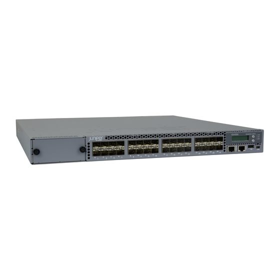
EX4550-32T switch. Figure 2: Front Panel of an EX4550-32T Switch Figure 3 on page 5 shows the rear panel of an EX4550 switch with power supplies and fan modules installed. Figure 3: Rear Panel of an EX4550 Switch... -
Page 28: Virtual Chassis
Virtual Chassis Hardware Configurations” on page 121. You can use the following ports to connect an EX4550 switch in a Virtual Chassis: Dedicated VCPs on the Virtual Chassis module installed in the switch SFP+ network ports and SFP+ expansion module ports configured as VCPs... -
Page 29: Power Supplies
EX4550-32F-S switches are not shipped with pre-installed power supplies; you must order them separately. You can install a second AC or DC power supply in the EX4550 switches. See “AC Power Supply in EX4550 Switches”... -
Page 30: Components On The Ex4550 Switch
EX4550 Switch Hardware Guide All the EX4550 switchmodels, except the EX4550-32F-S switches are shipped with three fan modules pre-installed in the rear panel of the switches. EX4550-32F-S switches are not shipped with pre-installed fan modules; you must order them separately. -
Page 31: Ex4550 Switch Models
Ethernet network ports Figure 6 on page 9 shows the components on the rear panel of an EX4550 switch (with the module slot cover panel, an AC power supply, and three fan modules installed). Figure 6: Components on the Rear Panel of an EX4550 Switch 1—... -
Page 32: Table 4: Ex4550 Switch Model Number, Shipped Components, And Supported
EX4550 Switch Hardware Guide Table 4: EX4550 Switch Model Number, Shipped Components, and Supported Junos OS Release First Junos Number and Model Number Types of Ports Direction of Airflow Fan Modules Power Supply Release EX4550-32F-AFI 32-port 10-Gigabit Back-to-front—air Three fan One AC power 12.2R1... - Page 33 Chapter 1: System Overview Table 4: EX4550 Switch Model Number, Shipped Components, and Supported Junos OS Release (continued) First Junos Number and Model Number Types of Ports Direction of Airflow Fan Modules Power Supply Release EX4550-32T-AFI 32-port 10-Gigabit Back-to-front—air Three fan One AC power 12.2R4...
-
Page 34: Identifying Ex4550 Switch Models
EX4550 Switch Hardware Guide Identifying EX4550 Switch Models Purpose Identify the model number of your EX4550 switch. Action Check the value of the FRU Model Number field in the Routing Engine section in the output of the show chassis hardware extensive CLI command. -
Page 35: Ex4550 Switch Hardware And Cli Terminology Mapping
EX4550 Switch Models on page 9 Documentation EX4550 Switch Hardware and CLI Terminology Mapping This topic describes the hardware terms used in EX4550 switch documentation and the corresponding terms used in the Junos OS CLI. See Table 5 on page... -
Page 36: Table 8: Expansion Modules In Ex4550 Switches
EX4550 Switch Hardware Guide Table 5: CLI Equivalents of Terms Used in the Documentation for EX4550 Switches (continued) Hardware Description Item (CLI) (CLI) Value (CLI) Item in Documentation Additional Information PIC (n) Abbreviated n is a value in the range 0... - Page 37 Chapter 1: System Overview Table 5: CLI Equivalents of Terms Used in the Documentation for EX4550 Switches (continued) Hardware Description Item (CLI) (CLI) Value (CLI) Item in Documentation Additional Information JPSU-650W AC and DC power supplies DC Power Supply in...
- Page 38 EX4550 Switch Hardware Guide Copyright © 2017, Juniper Networks, Inc.
-
Page 39: Chassis Components And Descriptions
Chassis Status LEDs in EX4550 Switches on page 28 Management Port LEDs in EX4550 Switches on page 29 Network Port and Expansion Module Port LEDs in EX4550 Switches on page 30 Chassis Physical Specifications for EX4550 Switches The EX4550 switch chassis is a rigid sheet-metal structure that houses all components of the switch. -
Page 40: Field-Replaceable Units In Ex4550 Switches
EX4550 Switch Hardware Guide You can mount an EX4550 switch on a standard 19-in. two-post rack. You can also mount the switch on a standard 19-in. four-post rack or in a standard 19-in. enclosed cabinet. Related Rack Requirements on page 78... -
Page 41: Lcd Panel In Ex4550 Switches
Chapter 2: Chassis Components and Descriptions LCD Panel in EX4550 Switches The LCD panel of the EX4550 switch shows two lines of text, each that can contain a maximum of 16 characters. The LCD panel displays a variety of information about the switch and also provides a menu to perform basic operations such as initial setup and reboot. -
Page 42: Lcd Panel Menus
EX4550 Switch Hardware Guide In an EX4550 switch that is a member of a Virtual Chassis, the first line of the LCD panel always displays: The slot number (the member ID for the Virtual Chassis member) Role of the switch in the Virtual Chassis (... -
Page 43: Chassis Components And Descriptions
ADM (administrative status) DPX (duplex) SPD (speed) “Network Port and Expansion Module Port LEDs in EX4550 Switches” on page 30 for information about the Status LED modes. Press Menu to exit the Idle menu and go to the Status menu. - Page 44 EX4550 Switch Hardware Guide Table 7: LCD Panel Menu Options in EX4550 Switches (continued) Menu Label Description MAINT The Maintenance menu has the following options to configure and troubleshoot the switch: (Maintenance SYSTEM HALT?—Choose one of the following: Menu) Press Enter to halt the switch. Press Enter again to confirm the halt.
-
Page 45: Expansion Modules In Ex4550 Switches
You must order them separately. You can install up to two expansion modules in an EX4550 switch—one in each of the module slots on the front panel and the rear panel of the switch. By installing an expansion module, you add more ports to your switch, thereby increasing the port density of the switch. -
Page 46: Figure 8: 8-Port Sfp+ Expansion Module
Each expansion module has an LED on the faceplate (labeled ). It indicates the status of the expansion module. Figure 11 on page 25 shows the location of LEDs on the SFP+ expansion module. Copyright © 2017, Juniper Networks, Inc. -
Page 47: Figure 11: Leds On An Sfp+ Expansion Module
Each SFP+ expansion module port and QSFP+ expansion module port has a pair of LEDs that indicate the link activity and status of the port and each 10GBASE-T expansion module port has an LED that indicates the link activity of the port. Copyright © 2017, Juniper Networks, Inc. -
Page 48: Virtual Chassis Module In Ex4550 Switches
EX4550 switch chassis. The Virtual Chassis module has two dedicated Virtual Chassis ports (VCPs), using which you can interconnect the EX4550 switch to an EX4200, EX4500, or EX4550 switch in a Virtual Chassis configuration. Figure 14 on page 26 shows the Virtual Chassis module. -
Page 49: Figure 15: Virtual Chassis Module Led
EX4500 switches through SFP+ expansion module ports or SFP+ network ports configured as VCPs to form a Virtual Chassis. You can also configure 10GBASE-T network ports, 10GBASE-T expansion module ports, or QSFP+ expansion module ports as VCPs to interconnect EX4550 switches in a Virtual Chassis. NOTE:... -
Page 50: Chassis Status Leds In Ex4550 Switches
EX4550 Switches Hardware Overview on page 3 Chassis Status LEDs in EX4550 Switches The front panel of an EX4550 switch has three chassis status LEDs (labeled ) on the far right side of the panel, next to the Menu and Enter buttons (see Figure 16 on page 28). -
Page 51: Management Port Leds In Ex4550 Switches
EX4550 Switches Hardware Overview on page 3 Management Port LEDs in EX4550 Switches The management port, which is on the front panel of an EX4550 switch, has two LEDs that indicate link activity and status of the management port (see Figure 17 on page 29). -
Page 52: Network Port And Expansion Module Port Leds In Ex4550 Switches
EX4550 Switch Hardware Guide Table 12: Link/Activity LED on the Management Port on an EX4550 Switch Color State and Description Link/Activity Green Blinking—The port and the link are active, and there is link activity. On steadily—The port and the link are active, but there is no link activity. -
Page 53: Figure 19: 10Gbase-T Ethernet Network Port And 10Gbase-T Expansion Module
LED that indicate the link activity of the port. Each LED is shaped to point toward the port for which it displays the link activity. Figure 20 on page 31 shows the LEDs on the QSFP+ expansion module ports of an EX4550 switch. Figure 20: QSFP+ Expansion Module Port LEDs Each QSFP+ expansion module port has two LEDs that indicate link activity and status of the expansion module ports. -
Page 54: Table 15: Status Led On Sfp+ Network Ports And Expansion Module Ports
Status LED on SFP+ network ports and SFP+ expansion module ports in EX4550 switches. From the Idle menu of the LCD panel, use the Enter button on the LCD panel to toggle between the ADM, DPX, and SPD indicators. - Page 55 Chapter 2: Chassis Components and Descriptions Related Expansion Modules in EX4550 Switches on page 23 Documentation EX4550 Switches Hardware Overview on page 3 Copyright © 2017, Juniper Networks, Inc.
- Page 56 EX4550 Switch Hardware Guide Copyright © 2017, Juniper Networks, Inc.
-
Page 57: Cooling System And Airflow
Cooling System and Airflow in an EX4550 Switch on page 35 Cooling System and Airflow in an EX4550 Switch The cooling system in an EX4550 switch consists of three fan modules and a single fan in each power supply. EX4550 switches provide back-to-front airflow (air comes in from the back of the switch) or front-to-back (air exhausts through the back of the switch) airflow depending on the fan modules and power supplies installed in the switch. -
Page 58: Airflow Direction In Ex4550 Switches
EX4550 switches except the EX4550-32F-S switches have the fan modules and power supplies preinstalled on the rear panel of the switches. Power supplies and fan modules for the EX4550-32F-S switch are not shipped by default; you must order them separately. -
Page 59: Back-To-Front Airflow
) with different airflow labels in the same chassis. Back-to-Front Airflow In the EX4550 switches that have back-to-front airflow, the air intake to cool the chassis is through the vents on the rear panel, and hot air exhausts through the vents on the front panel of the switch. -
Page 60: Front-To-Back Airflow
AIR IN (AFI) Front-to-Back Airflow In the EX4550 switches that have front-to-back airflow, the air intake to cool the chassis is through the vents on the front panel of the switch, and hot air exhausts through the vents on the rear panel. See... -
Page 61: Fan Module Status
) for each fan module on the left side of the corresponding fan module slot. It indicates the status of the fan module. Table 19 on page 39 describes the Status LED on a fan module in an EX4550 switch. Table 19: Fan Module LED State... - Page 62 EX4550 Switch Hardware Guide Copyright © 2017, Juniper Networks, Inc.
-
Page 63: Power Supplies
This topic describes the AC power supplies. The AC power supply in EX4550 switches gives an output of 650 W and supports both low line voltage (100–120 VAC) and high line voltage (200–240 VAC). -
Page 64: Figure 25: Label Identifying The Airflow Direction In An Ac Power Supply
To avoid electrical injury while installing or removing AC power supplies, carefully follow instructions in “Installing an AC Power Supply in an EX4550 Switch” on page 199 “Removing an AC Power Supply from an EX4550 Switch” on page 201. -
Page 65: Ac Power Supply Leds In Ex4550 Switches
Installing an AC Power Supply in an EX4550 Switch on page 199 AC Power Supply LEDs in EX4550 Switches Figure 26 on page 43 shows the location of the LEDs on an AC power supply for an EX4550 switch. Figure 26: AC Power Supply LEDs in an EX4550 Switch... -
Page 66: Dc Power Supply In Ex4550 Switches
(FRU): You can install it without powering off the switch or disrupting the switching function. All the EX4550 switches that are powered by DC power supplies, except the EX4550-32F-S switches are shipped with one DC power supply pre-installed in the rear panel of the switches. -
Page 67: Figure 27: Dc Power Supply For An Ex4550 Switch
3— Ejector lever 2—Terminal block The DC power supply in EX4550 switches is a hot-insertable and hot-removable field-replaceable unit (FRU): You can install it without powering off the switch or disrupting the switching function. Two variants of DC power supplies are available, each with a different airflow:... -
Page 68: Dc Power Supply Leds In Ex4550 Switches
Installing a DC Power Supply in an EX4550 Switch on page 202 DC Power Supply LEDs in EX4550 Switches Figure 29 on page 47 shows the location of the LEDs on a DC power supply for an EX4550 switch. Copyright © 2017, Juniper Networks, Inc. -
Page 69: Figure 29: Dc Power Supply Faceplate On An Ex4550 Switch
Chapter 4: Power Supplies Figure 29: DC Power Supply Faceplate on an EX4550 Switch 1— V+ input terminals 5— ESD grounding point 2— V– input terminals 6— ! (Fault) LED 3— Terminal block 7— OUT (Output) LED 4— Ejector lever 8—... - Page 70 EX4550 Switch Hardware Guide Connecting DC Power to an EX4550 Switch on page 159 Copyright © 2017, Juniper Networks, Inc.
-
Page 71: Viewing System Information
NOTE: This topic applies only to the J-Web Application package. When you log in to the J-Web user interface, the dashboard for the Juniper Networks EX Series Ethernet Switches appears. Use the dashboard to view system information. The Update Available window appears if there is a latest update of the J-Web Application package available on the Juniper Networks server. -
Page 72: Graphical Chassis Viewer
Virtual Chassis. If the member switch does not appear dimmed, it means the switch is present and is active. Table 25 on page 51 describes the possible status of a member switch. Copyright © 2017, Juniper Networks, Inc. -
Page 73: System Information Panel
NOTE: In a Virtual Chassis setup for an EX6210, EX8208, or EX8216 switch, the Device model field displays details of the master Routing Engine. To view details of a member, select it. Copyright © 2017, Juniper Networks, Inc. - Page 74 Virtual Chassis, the value displayed in Inventory details field is always 1 FPC. FPC is a legacy term for a slot in a large Juniper Networks chassis; which simply refers to the standalone switch. For EX2200 and EX2200-C switches configured as a Virtual Chassis, the value displayed in the Inventory details field is 1–4 FPC, with the number corresponding to the number of...
-
Page 75: Health Status Panel
Indicates the average CPU usage over 15 minutes. In a Virtual Chassis configuration, on loading the master or backup switch, the CPU load for that switch's Routing Engine is displayed by default. To display the CPU load for a specific switch's Routing Engine, click the image of that switch. Copyright © 2017, Juniper Networks, Inc. - Page 76 Routing Engine. CPU load Indicates the average CPU usage over 15 minutes. Flash Indicates the usage and capacity of internal flash memory and any external USB flash drive. EX8216 Switches Copyright © 2017, Juniper Networks, Inc.
-
Page 77: Capacity Utilization Panel
Alarms Panel Displays information about the last five alarms raised in the system. For example, if there are 5 major alarms, then details of all 5 major alarms are displayed. If there are 4 major Copyright © 2017, Juniper Networks, Inc. -
Page 78: File System Usage
59—Describes the chassis viewer for EX4300 switches. Table 33 on page 60—Describes the chassis viewer for EX4500 switches. Table 34 on page 61—Describes the chassis viewer for EX4550 switches. Table 35 on page 63—Describes the chassis viewer for EX4600 switches. Table 36 on page 63—Describes the chassis viewer for EX6210 switches. -
Page 79: Table 30: Chassis Viewer For Ex2200-C Switches
USB port Indicates the USB port for the switch. NOTE: We recommend that you use USB flash drives purchased from Juniper Networks for your EX Series switch. Fan tray Mouse over the fan tray icon to display name, status, and description information. - Page 80 USB port Indicates the USB port for the switch. NOTE: We recommend that you use USB flash drives purchased from Juniper Networks for your EX Series switch. Fan tray Mouse over the fan tray icon to display name, status, and description information.
-
Page 81: Table 32: Chassis Viewer For Ex4300 Switches
Description USB port Indicates the USB port for the switch. NOTE: We recommend that you use USB flash drives purchased from Juniper Networks for your EX Series switch. Management ( ) port The management port is used to connect the switch to a management device for out-of-band management. -
Page 82: Table 33: Chassis Viewer For Ex4500 Switches
USB port Indicates the USB port for the switch. NOTE: We recommend that you use USB flash drives purchased from Juniper Networks for your EX Series switch. Fan tray Mouse over the fan tray icons to display name, status, and description information. -
Page 83: Table 34: Chassis Viewer For Ex4550 Switches
Use this port for initial switch configuration. USB port Indicates the USB port for the switch. NOTE: We recommend that you use USB flash drives purchased from Juniper Networks for your EX Series switch. Rear View of the EX4500 Switch Fan tray Mouse over the fan tray icon to display status of the fans and airflow direction information. - Page 84 If an expansion module or a Virtual Chassis module is installed in the switch, mouse over the interface (ports) on the module for more information. On an EX4550-32F switch, for SFP and SFP+ ports, the interfaces appear dimmed if no transceiver is inserted. The chassis viewer displays...
-
Page 85: Table 35: Chassis Viewer For Ex4600 Switches
USB port Indicates the USB port for the switch. NOTE: We recommend that you use USB flash drives purchased from Juniper Networks for your EX Series switch. Fan tray Mouse over the fan tray icons to display name, status, and description information. -
Page 86: Table 37: Chassis Viewer For Ex8208 Switches
You can view status for the following ports on the SRE module: USB port—Indicates the USB port for the switch. NOTE: We recommend that you use USB flash drives purchased from Juniper Networks for your EX Series switch. Management ( ) port—The management port is used to connect the switch to a management... - Page 87 You can view status for the following ports on the SRE module: USB port—Indicates the USB port for the switch. NOTE: We recommend that you use USB flash drives purchased from Juniper Networks for your EX Series switch. Auxiliary port—This port is unavailable.
-
Page 88: Table 38: Chassis Viewer For Ex8216 Switches
You can view status for the following ports on the RE module: USB port—Indicates the USB port for the switch. NOTE: We recommend that you use USB flash drives purchased from Juniper Networks for your EX Series switch. Auxiliary port—This port is unavailable. - Page 89 USB port Indicates the USB port for the switch. NOTE: We recommend that you use USB flash drives purchased from Juniper Networks for your EX Series switch. PIC1 slot You can install a Virtual Chassis module in the PIC1 slot. Mouse over the Virtual Chassis ports to display the port status details.
- Page 90 EX4300 Switches Hardware Overview EX4500 Switches Hardware Overview EX6210 Switch Hardware Overview EX8208 Switch Hardware Overview EX8216 Switch Hardware Overview Checking Active Alarms with the J-Web Interface on page 250 XRE200 External Routing Engine Hardware Guide Copyright © 2017, Juniper Networks, Inc.
-
Page 91: Site Planning, Preparation, And Specifications
Site Planning, Preparation, and Specifications Preparation Overview on page 71 Power Specifications and Requirements on page 83 Transceiver and Cable Specifications on page 91 Pinout Specifications on page 109 Planning the Virtual Chassis on page 121 Copyright © 2017, Juniper Networks, Inc. - Page 92 EX4550 Switch Hardware Guide Copyright © 2017, Juniper Networks, Inc.
-
Page 93: Preparation Overview
CHAPTER 6 Preparation Overview Site Preparation Checklist for EX4550 Switches on page 71 Environmental Requirements and Specifications for EX Series Switches on page 72 General Site Guidelines on page 76 Site Electrical Wiring Guidelines on page 77 Chassis Physical Specifications for EX4550 Switches on page 77... -
Page 94: Environmental Requirements And Specifications For Ex Series Switches
General Safety Guidelines and Warnings on page 259 Documentation General Site Guidelines on page 76 Installing and Connecting an EX4550 Switch on page 139 Mounting an EX4550 Switch on page 140 Environmental Requirements and Specifications for EX Series Switches The switch must be installed in a rack or cabinet housed in a dry, clean, well-ventilated, and temperature-controlled environment. -
Page 95: Table 41: Ex Series Switch Environmental Tolerances
Complies with Zone 4 degradation up to the relative humidity range temperature range 32° F (0° C) earthquake 10,000 feet 10% through 85% through 113° F (45° C) requirements as per (3048 meters) (noncondensing) GR-63, Issue 4. Copyright © 2017, Juniper Networks, Inc. - Page 96 32° F earthquake 10,000 feet 10% through 85% (0° C) through 104° F (40° C) requirements as per (3048 meters) (noncondensing) GR-63, Issue 4. Copyright © 2017, Juniper Networks, Inc.
- Page 97 GR-63, Issue 4. NOTE: Install EX Series switches only in restricted areas, such as dedicated equipment rooms and equipment closets, in accordance with Articles 110–16, 110–17, and 110–18 of the National Electrical Code, ANSI/NFPA 70. Copyright © 2017, Juniper Networks, Inc.
-
Page 98: General Site Guidelines
Clearance Requirements for Airflow and Hardware Maintenance for an EX Series Redundant Power System Clearance Requirements for Airflow and Hardware Maintenance for EX4500 Switches Clearance Requirements for Airflow and Hardware Maintenance for EX4550 Switches on page 80 Clearance Requirements for Airflow and Hardware Maintenance for an EX6210 Switch... -
Page 99: Site Electrical Wiring Guidelines
General Electrical Safety Guidelines and Warnings on page 287 Prevention of Electrostatic Discharge Damage on page 289 Chassis Physical Specifications for EX4550 Switches The EX4550 switch chassis is a rigid sheet-metal structure that houses all components of the switch. Table 6 on page 17 summarizes the physical specifications of the EX4550 switch chassis. -
Page 100: Rack Requirements
QSFP+ expansion module port: 0.61 lb (0.28 kg) Virtual Chassis module: 0.66 lb (0.3 kg) You can mount an EX4550 switch on a standard 19-in. two-post rack. You can also mount the switch on a standard 19-in. four-post rack or in a standard 19-in. enclosed cabinet. -
Page 101: Cabinet Requirements
You can mount the device in a cabinet that contains a 19-in. rack as defined by the Electronics Industry Association. The minimum cabinet size must be able to accommodate the maximum external dimensions of the device. Copyright © 2017, Juniper Networks, Inc. -
Page 102: Switches
Rack-Mounting and Cabinet-Mounting Warnings on page 270 Documentation Clearance Requirements for Airflow and Hardware Maintenance for EX4550 Switches When planning the site for installing an EX4550 switch, you must allow sufficient clearance around the switch. Follow these clearance requirements: Copyright © 2017, Juniper Networks, Inc. -
Page 103: Figure 30: Back-To-Front Airflow
Leave at least 6 in. (15.2 cm) clearance on the left of the chassis for installing the grounding lug. Leave at least 24 in. (61 cm) clearance on front and of the switch for service personnel to remove and install hardware components. See Figure 32 on page Copyright © 2017, Juniper Networks, Inc. -
Page 104: Figure 32: Clearance Requirements For Airflow And Hardware Maintenance For
Chassis Physical Specifications for EX4550 Switches on page 17 Documentation Rack-Mounting and Cabinet-Mounting Warnings on page 270 General Site Guidelines on page 76 Cooling System and Airflow in an EX4550 Switch on page 35 Copyright © 2017, Juniper Networks, Inc. -
Page 105: Power Specifications And Requirements
Power Specifications and Requirements AC Power Supply Specifications for EX4550 Switches on page 83 AC Power Cord Specifications for an EX4550 Switch on page 84 DC Power Supply Specifications for EX4550 Switches on page 87 Calculating the EX Series Switch Fiber-Optic Cable Power Budget on page 88... -
Page 106: Ac Power Cord Specifications For An Ex4550 Switch
EX4550 Switch Hardware Guide Table 46: AC Power Supply Specifications for an EX4550 Switch (continued) Item Specification System Thermal Output of EX4550-32T switches with two 1375 BTU/Hour EX4550-EM-8XT expansion modules installed = (Maximum System Power Requirement ) * 3.41 NOTE: 1 W = 3.41 BTU/Hour... - Page 107 Chapter 7: Power Specifications and Requirements Table 47: AC Power Cord Specifications for an EX4550 Switch (continued) Country/Region Electrical Specifications Plug Standards Juniper Model number Graphic China 250 VAC, 10 A, 50 Hz GB 1002-1996 Type CBL-EX-PWR-C13-CH PRC/3 Europe 250 VAC, 10 A, 50 Hz...
- Page 108 EX4550 Switch Hardware Guide Table 47: AC Power Cord Specifications for an EX4550 Switch (continued) Country/Region Electrical Specifications Plug Standards Juniper Model number Graphic Israel 250 VAC, 10 A, 50 Hz SI 32/1971 Type IL/3G CBL-EX-PWR-C13-IL Italy 250 VAC, 10 A, 50 Hz...
-
Page 109: Dc Power Supply Specifications For Ex4550 Switches
BS 1363/A Type BS89/13 CBL-EX-PWR-C13-UK Kingdom CAUTION: The AC power cord for the EX4550 switch is intended for use with this switch only. Do not use the cord with any other product. CAUTION: Power cords must not block access to switch components. -
Page 110: Calculating The Ex Series Switch Fiber-Optic Cable Power Budget
DC Power Supply in EX4550 Switches on page 44 Documentation DC Power Supply LEDs in EX4550 Switches on page 46 Calculating the EX Series Switch Fiber-Optic Cable Power Budget Calculate the link's power budget when planning fiber-optic cable layout and distances to ensure that fiber-optic connections have sufficient power for correct operation. -
Page 111: Table 49: Estimated Values For Factors Causing Link Loss
1 dBm NOTE: For information about the actual amount of signal loss caused by equipment and other factors, see your vendor documentation for that equipment. Calculate the (P ) by subtracting (LL) from (P Copyright © 2017, Juniper Networks, Inc. - Page 112 Calculating the EX Series Switch Fiber-Optic Cable Power Budget on page 88 Documentation Understanding EX Series Switches Fiber-Optic Cable Signal Loss, Attenuation, and Dispersion on page 106 Pluggable Transceivers Supported on EX Series Switches on page 92 Copyright © 2017, Juniper Networks, Inc.
-
Page 113: Transceiver And Cable Specifications
Pluggable Transceivers Supported on EX4550 Switches Uplink module ports on EX4550 switches support SFP, SFP+, and QSFP+ transceivers. You can find the list of transceivers supported on EX4550 switches and information about those transceivers at the Hardware Compatibility Tool page for EX4550... -
Page 114: Pluggable Transceivers Supported On Ex Series Switches
For the list and specifications of transceivers supported on EX4500 switches, see Pluggable Transceivers Supported on EX4500 Switches. For the list and specifications of transceivers supported on EX4550 switches, see “Pluggable Transceivers Supported on EX4550 Switches” on page Copyright © 2017, Juniper Networks, Inc. -
Page 115: Sfp+ Direct Attach Copper Cables For Ex Series Switches
3 m, 5 m, and 7 m long SFP+ passive DAC cables. For the full specifications of these cables, see The Hardware Compatibility Tool Table 50 on page 94 describes the support for SFP+ passive DAC cable lengths on EX Series switches for Junos OS releases. Copyright © 2017, Juniper Networks, Inc. -
Page 116: Junos Os Release
3 ft (1 m), 10 ft (3 m), 16 ft (5 m), and 23 ft (7 m) EX4500 switches Junos OS Release 10.2 3 ft (1 m), 10 ft (3 m), and 23 ft (7 m) Junos OS Release 11.2 16 ft (5 m) Copyright © 2017, Juniper Networks, Inc. - Page 117 (JTAC) can help you diagnose the source of the problem. Your JTAC engineer might recommend that you check the third-party optic or cable and potentially replace it with an equivalent Juniper Networks optic or cable that is qualified for the device.
-
Page 118: Table 51: Sfp+ Direct Attach Copper Cable Specifications
30 AWG Minimum cable bend radius 1 in. (2.54 cm) Cable characteristic impedance 100 ohms Crosstalk between pairs 2% maximum Time delay 1.31 nsec/ft Length 3.3 ft (1 m) Support for Virtual Chassis configuration Copyright © 2017, Juniper Networks, Inc. - Page 119 30 AWG Minimum cable bend radius 1 in. (2.54 cm) Cable characteristic impedance 100 ohms Crosstalk between pairs 2% maximum Time delay 1.31 nsec/ft Length 9.9 ft (3 m) Support for Virtual Chassis configuration Copyright © 2017, Juniper Networks, Inc.
- Page 120 24 AWG Minimum cable bend radius 1 in. (2.54 cm) Cable characteristic impedance 100 ohms Crosstalk between pairs 2% maximum Time delay 1.31 nsec/ft Length 16.4 ft (5 m) Support for Virtual Chassis configuration Copyright © 2017, Juniper Networks, Inc.
-
Page 121: Standards Supported By These Cables
Electrical interface standard SFF-8432—see ftp://ftp.seagate.com/sff/SFF-8432.PDF SFP+ Multi-Source Alliance (MSA) standards Related Pluggable Transceivers Supported on EX Series Switches on page 92 Documentation Installing a Transceiver on page 213 Removing a Transceiver on page 215 Copyright © 2017, Juniper Networks, Inc. -
Page 122: Qsfp+ Direct Attach Copper Cables For Ex Series Switches
EX Series switches for Junos OS releases. Table 52: Software Support for QSFP+ Passive Direct Attach Copper Cables for EX Series Switches Switch Software Support Added DAC Model Number EX3400 switches Junos OS Release 15.1X53-D50 EX-QSFP-40GE-DAC-50CM QFX-QSFP-DAC-1M QFX-QSFP-DAC-3M JNP-QSFP-DAC-5M Copyright © 2017, Juniper Networks, Inc. - Page 123 (JTAC) can help you diagnose the source of the problem. Your JTAC engineer might recommend that you check the third-party optic or cable and potentially replace it with an equivalent Juniper Networks optic or cable that is qualified for the device.
-
Page 124: Table 53: Qsfp+ Direct Attach Copper Cable Specifications
30 AWG Minimum cable bend radius 2.54 cm (1 in.) Cable characteristic impedance 100 ohms Crosstalk between pairs 1% maximum Time delay 4.3 nsec/ft Length 1.6 ft (0.5 m) Support for Virtual Chassis configuration Copyright © 2017, Juniper Networks, Inc. - Page 125 30 AWG Minimum cable bend radius 2.54 cm (1 in.) Cable characteristic impedance 100 ohms Crosstalk between pairs 1% maximum Time delay 4.3 nsec/ft Length 3.28 ft (1 m) Support for Virtual Chassis configuration Copyright © 2017, Juniper Networks, Inc.
- Page 126 30 AWG Minimum cable bend radius 2.54 cm (1 in.) Cable characteristic impedance 100 ohms Crosstalk between pairs 1% maximum Time delay 4.3 nsec/ft Length 9.84 ft (3 m) Support for Virtual Chassis configuration Copyright © 2017, Juniper Networks, Inc.
-
Page 127: Management Cable Specifications
Ports Cable Specifications Receptacle Additional Information RJ-45 Console ( CON2 ) port CAT5e UTP (unshielded RJ-45 “Connecting a Device to a twisted pair) cable Management Console by Using an RJ-45 Connector” on page 166 Copyright © 2017, Juniper Networks, Inc. -
Page 128: Understanding Ex Series Switches Fiber-Optic Cable Signal Loss, Attenuation, And Dispersion
An optical data link functions correctly provided that modulated light reaching the receiver has enough power to be demodulated correctly. Attenuation is the reduction in strength of the light signal during transmission. Passive media components such as cables, cable Copyright © 2017, Juniper Networks, Inc. - Page 129 (including those from dispersion), and a safety margin for unexpected losses. Related Calculating the EX Series Switch Fiber-Optic Cable Power Budget on page 88 Documentation Calculating the EX Series Switch Fiber-Optic Cable Power Margin on page 88 Copyright © 2017, Juniper Networks, Inc.
- Page 130 EX4550 Switch Hardware Guide Copyright © 2017, Juniper Networks, Inc.
-
Page 131: Pinout Specifications
Virtual Chassis Port Connector Pinout Information for EX4550 Switches on page 117 Console Port Connector Pinout Information The console port on a Juniper Networks device is an RS-232 serial interface that uses an RJ-45 connector to connect to a console management device. The default baud rate for the console port is 9600 baud. -
Page 132: Mini-Usb Port Pinout Specifications
Management Cable Specifications on page 105 Documentation USB Port Specifications for an EX Series Switch The following Juniper Networks USB flash drives have been tested and are officially supported for the USB port on all EX Series switches: Copyright © 2017, Juniper Networks, Inc. - Page 133 CAUTION: Any USB memory product not listed as supported for EX Series switches has not been tested by Juniper Networks. The use of any unsupported USB memory product could expose your EX Series switch to unpredictable behavior. Juniper Networks Technical Assistance Center (JTAC) can provide only limited support for issues related to unsupported hardware.
-
Page 134: Rj-45 Management Port Connector Pinout Information
EX4550 Switch Hardware Guide RJ-45 Management Port Connector Pinout Information Table 57 on page 112 provides the pinout information for the RJ-45 connector for the management port on Juniper Networks devices. Table 57: RJ-45 Management Port Connector Pinout Information Signal Description... -
Page 135: Table 59: Sfp Network Port Connector Pinout Information
2-wire serial interface data line SCL- 2-wire serial interface clock MOD_ABS Module absent Rate select RX_LOS Receiver loss of signal indication VeeR Module receiver ground VeeR Module receiver ground VeeR Module receiver ground Receiver inverted data output Copyright © 2017, Juniper Networks, Inc. -
Page 136: Table 60: Sfp+ Network Port Connector Pinout Information
Rate select 0, optionally controls SFP+ module receiver RX_LOS Receiver loss of signal indication Rate select 1, optionally controls SFP+ transmitter VeeR Module receiver ground VeeR Module receiver ground Receiver inverted data output Receiver noninverted data output VeeR Module receiver ground Copyright © 2017, Juniper Networks, Inc. -
Page 137: Table 61: Qsfp+ Network Port Connector Pinout Information
VeeT Module transmitter ground Transmitter noninverted data input Transmitter inverted data input VeeT Module transmitter ground Table 61: QSFP+ Network Port Connector Pinout Information Signal TX2n TX2p TX4n TX4p ModSelL LPMode_Reset VccRx RX3p RX3n Copyright © 2017, Juniper Networks, Inc. - Page 138 EX4550 Switch Hardware Guide Table 61: QSFP+ Network Port Connector Pinout Information (continued) Signal RX1p RX1n RX2n RX2p RX4n RX4p ModPrsL IntL VccTx Vcc1 Reserved TX3p TX3n TX1p TX1n Related Installing a Transceiver on page 213 Documentation Copyright © 2017, Juniper Networks, Inc.
-
Page 139: Rj-45 To Db-9 Serial Port Adapter Pinout Information
Connecting a Device to a Management Console by Using an RJ-45 Connector on page 166 Documentation Virtual Chassis Port Connector Pinout Information for EX4550 Switches EX4550 switches use a 68-pin connector cable to interconnect switches to form a Virtual Chassis. Table 63 on page 117 provides connector pinout information for the Virtual Chassis ports (VCPs). - Page 140 EX4550 Switch Hardware Guide Table 63: Virtual Chassis Ports (VCPs) Connector Pinout Information (continued) Pin Number Pin Name P1TXP1 P1TXN1 P1TXP2 P1TXN2 P1TXP3 P1TXN3 P2TXP0 P2TXN0 P2TXP1 P2TXN1 Copyright © 2017, Juniper Networks, Inc.
- Page 141 Chapter 9: Pinout Specifications Table 63: Virtual Chassis Ports (VCPs) Connector Pinout Information (continued) Pin Number Pin Name P2TXP2 P2TXN2 P2TXP3 P2TXN3 P1RXP0 P1RXN0 P1RXP1 P1RXN1 P1RXP2 P1RXN2 P1RXP3 P1RXN3 Copyright © 2017, Juniper Networks, Inc.
- Page 142 Planning EX4200, EX4500, and EX4550 Virtual Chassis on page 124 Documentation Understanding EX Series Virtual Chassis Components Understanding EX Series Virtual Chassis Configuration Connecting a Virtual Chassis Cable to an EX4550 Switch on page 227 Copyright © 2017, Juniper Networks, Inc.
-
Page 143: Planning The Virtual Chassis
EX4200 switches. You can interconnect EX4500 switches together to form a Virtual Chassis composed exclusively of EX4500 switches. You can interconnect EX4550 switches together to form a Virtual Chassis composed exclusively of EX4550 switches. You can also interconnect EX4200 switches with EX4500 switches or with EX4550 switches or with both switches to form a mixed Virtual Chassis. -
Page 144: Number Of Switches, Required Software Releases, And Member Roles That You Configure In The Virtual Chassis
The number of switches that you can configure in a Virtual Chassis and the role that can be assigned to each switch in a Virtual Chassis depend on the Juniper Networks Junos operating system (Junos OS) release that is running on the switches. -
Page 145: Virtual Chassis Module
Up to 10 EX4500 switches There must be a master and a backup; the remaining switches must be in the linecard role. Table 66: Number of Switches and Switch Roles for an EX4550 Virtual Chassis, per Junos OS Release Junos OS Release... -
Page 146: Switch Role And Member Id On The Lcd Panel
Planning EX4200, EX4500, and EX4550 Virtual Chassis on page 124 EX Series Virtual Chassis Overview Planning EX4200, EX4500, and EX4550 Virtual Chassis Before interconnecting EX4200, EX4500, and EX4550 switches in a Virtual Chassis configuration: Verify that the rack in which you will install the switches meets the requirements described in “Rack Requirements”... -
Page 147: Table 69: Cabling Requirements For A Virtual Chassis
0.5 m through 5 m 1 m, 3 m, and 5 m You must order these cables separately for EX4200, EX4500, and EX4550 switches, including EX4500 switches that are shipped with a preinstalled Virtual Chassis module. Copyright © 2017, Juniper Networks, Inc. -
Page 148: Virtual Chassis Cabling Configuration Examples For Ex4550 Switches
Clearance Requirements for Airflow and Hardware Maintenance for EX4500 Switches Virtual Chassis Cabling Configuration Examples for EX4550 Switches You can install EX4550 switches on a single rack or in multiple racks, or in different wiring closets, and interconnect them to form a Virtual Chassis. -
Page 149: Figure 35: Ex4550 Switches Mounted On A Single Rack And Connected In A Ring Topology Using Virtual Chassis Module And Using Short And Long Cables
Virtual Chassis module and using four short Virtual Chassis cables and one long Virtual Chassis cable. Figure 35: EX4550 Switches Mounted on a Single Rack and Connected in a Ring Topology Using Virtual Chassis Module and Using Short and Long Cables: Example 1 Copyright ©... -
Page 150: Figure 36: Ex4550 Switches Mounted On A Single Rack And Connected In A Ring Topology Using Virtual Chassis Module And Using Short And Long Cables
EX4550 Switch Hardware Guide Figure 36: EX4550 Switches Mounted on a Single Rack and Connected in a Ring Topology Using Virtual Chassis Module and Using Short and Long Cables: Example 2 Figure 37 on page 128 shows five EX4550 switches stacked vertically in a rack and interconnected in a ring topology using Virtual Chassis module and using short-length and medium-length Virtual Chassis cables. -
Page 151: Figure 38: Ex4550 Switches Mounted On Adjacent Racks And Connected In A Ring Topology Using Virtual Chassis Module And Using Medium And Long
Ring Topology Using 8-port 10GBASE-T Expansion Module and Using Short and Long Cables: Example 1 Figure 41: EX4550 Switches Mounted on a Single Rack and Connected in a Ring Topology Using 8-port 10GBASE-T Expansion Module and Using Short and Long Cables: Example 2... -
Page 152: Figure 42: Ex4550 Switches Mounted On A Single Rack And Connected In A Ring
8-port 10GBASE-T expansion module and using short-length and medium-length cables. Figure 42: EX4550 Switches Mounted on a Single Rack and Connected in a Ring Topology Using 8-port 10GBASE-T Expansion Module and Using Short and Medium Cables... - Page 153 Chapter 10: Planning the Virtual Chassis Understanding EX Series Virtual Chassis Components Planning EX4200, EX4500, and EX4550 Virtual Chassis on page 124 Copyright © 2017, Juniper Networks, Inc.
- Page 154 EX4550 Switch Hardware Guide Copyright © 2017, Juniper Networks, Inc.
-
Page 155: Initial Installation And Configuration
Unpacking the Switch on page 135 Installing the Switch on page 139 Connecting the Switch to Power on page 151 Connecting the Switch to the Network on page 165 Performing Initial Configuration on page 171 Copyright © 2017, Juniper Networks, Inc. - Page 156 EX4550 Switch Hardware Guide Copyright © 2017, Juniper Networks, Inc.
-
Page 157: Unpacking The Switch
Related Installing and Connecting an EX4500 Switch Documentation Connecting and Configuring an EX Series Switch (CLI Procedure) on page 181 Connecting and Configuring an EX Series Switch (J-Web Procedure) on page 184 Copyright © 2017, Juniper Networks, Inc. -
Page 158: Parts Inventory (Packing List) For An Ex4500 Switch
See EX4500 Switch Models for more information. If any part on the packing list is missing, contact your customer service representative or contact Juniper customer care from within the U.S. or Canada by telephone at 1-888-314-5822. For international-dial or direct-dial options in countries without toll-free numbers, see http://www.juniper.net/support/requesting-support.html... -
Page 159: Registering Products-Mandatory For Validating Slas
Unpacking an EX4500 Switch on page 135 Documentation EX4500 Switches Hardware Overview Registering Products—Mandatory for Validating SLAs Register all new Juniper Networks hardware products and changes to an existing installed product using the Juniper Networks website to activate your hardware replacement service-level agreements (SLAs). CAUTION:... - Page 160 EX4550 Switch Hardware Guide Copyright © 2017, Juniper Networks, Inc.
-
Page 161: Installing The Switch
Mounting an EX4550 Switch on Four Posts in a Rack or Cabinet on page 143 Mounting an EX4550 Switch in a Recessed Position in a Rack or Cabinet on page 147 Installing and Removing EX4550 Switch Hardware Components on page 148... -
Page 162: Mounting An Ex4550 Switch
Mounting an EX4550 Switch on Two Posts in a Rack or Cabinet on page 141 Documentation Mounting an EX4550 Switch in a Recessed Position in a Rack or Cabinet on page 147 Mounting an EX4550 Switch on Four Posts in a Rack or Cabinet on page 143 Connecting Earth Ground to an EX Series Switch on page 151 Copyright ©... -
Page 163: Mounting An Ex4550 Switch On Two Posts In A Rack Or Cabinet
Mounting an EX4550 Switch on Two Posts in a Rack or Cabinet You can mount an EX4550 switch on two posts in a 19-in. rack or cabinet (either a two-post or a four-post rack or cabinet) by using the mounting brackets provided with the switch. -
Page 164: Figure 45: Attaching The Mounting Bracket To The Side Panel Of The Switch
Align the bottom hole in both the mounting brackets with a hole in each rack rail, making sure the chassis is level. See Figure 46 on page 143. Copyright © 2017, Juniper Networks, Inc. -
Page 165: Mounting An Ex4550 Switch On Four Posts In A Rack Or Cabinet
Mounting an EX4550 Switch on Four Posts in a Rack or Cabinet You can mount an EX4550 switch on four posts in a 19-in. rack or cabinet by using the separately orderable four-post rack-mount kit. (The remainder of this topic uses rack to mean rack or cabinet.) - Page 166 259, with particular attention “Chassis Lifting Guidelines” on page 268. Remove the switch from the shipping carton (see Unpacking an EX4550 Switch). Ensure that you have the following parts and tools available: Phillips (+) screwdriver, number 2 6 4-40 flat-head Phillips mounting screws (provided with the four-post rack-mount...
-
Page 167: Figure 47: Attaching The Front Mount Bracket To The Side Mounting-Rail
Chapter 12: Installing the Switch Cover panels for module slots Dust covers for ports (provided in the accessory box shipped with the EX4550-32F switches) NOTE: One person must be available to lift the switch while another secures it to the rack. -
Page 168: Figure 48: Attaching The Side Mounting-Rail To The Switch Chassis
Have a second person secure the front mount brackets to the rack by using the appropriate screws for your rack. Slide the rear mounting-blades into the side mounting-rails. See Figure 50 on page 147. Copyright © 2017, Juniper Networks, Inc. -
Page 169: Mounting An Ex4550 Switch In A Recessed Position In A Rack Or Cabinet
Mounting an EX4550 Switch in a Recessed Position in a Rack or Cabinet You can mount an EX4550 switch in a recessed position on two posts of either a two-post rack or a four-post rack such that the switch is recessed inside the rack from the rack front by 2 inches. -
Page 170: Installing And Removing Ex4550 Switch Hardware Components
To mount the switch in a recessed position on four posts, follow the instructions in “Mounting an EX4550 Switch on Two Posts in a Rack or Cabinet” on page 141 “Mounting an EX4550 Switch on Four Posts in a Rack or Cabinet”... - Page 171 Chapter 12: Installing the Switch Installing a Virtual Chassis Module in an EX4550 Switch on page 223 Removing a Virtual Chassis Module from an EX4550 Switch on page 224 Installing a Transceiver on page 213 Removing a Transceiver on page 215...
- Page 172 EX4550 Switch Hardware Guide Copyright © 2017, Juniper Networks, Inc.
-
Page 173: Connecting The Switch To Power
Connecting the Switch to Power Connecting Earth Ground to an EX Series Switch on page 151 Connecting AC Power to an EX4550 Switch on page 157 Connecting DC Power to an EX4550 Switch on page 159 Connecting Earth Ground to an EX Series Switch... -
Page 174: Table 71: Parts And Tools Required For Connecting An Ex Series Switch To Earth Ground
Phillips (+) of the minimum 90°C LCC10-14BWL or screws with #10 number 2 chassis wire, or as equivalent— split-lock washer— permitted by the not provided not provided local code Two #10 flat washers—not provided Copyright © 2017, Juniper Networks, Inc. -
Page 175: Special Instructions To Follow Before Connecting Earth Ground To A
Two ¼-20 x 0.5 in. Phillips (+) the chassis mm²), minimum LCD2-14A-Q or screws with #¼” number 2 60°C wire, or as equivalent split-washer permitted by the —provided —provided local code Two #¼” flat washers— provided Copyright © 2017, Juniper Networks, Inc. -
Page 176: Switch
Special Instructions EX3200 NOTE: Some early variants of EX3200 switches for which the Juniper Networks model number on the label next to the protective earthing terminal is from 750-021xxx through 750-030xxx require 10-24x.25 in. screws. Copyright © 2017, Juniper Networks, Inc. -
Page 177: Figure 51: Connecting The Grounding Lug To A Switch Mounted On Four Posts Of
NOTE: The protective earthing terminal on an EX4550 switch mounted on four posts of a rack is accessible through the slot on the left rear bracket only if the rack is 27.5 in. (69.85 cm) through 30.5 in. (77.47 cm) deep for a switch mounted flush with the rack front and 29.5 in. -
Page 178: Connecting Earth Ground To An Ex Series Switch
Connecting AC Power to an EX3300 Switch Connecting DC Power to an EX3300 Switch Connecting AC Power to an EX3400 Switch Connecting AC Power to an EX4200 Switch Connecting DC Power to an EX4200 Switch Copyright © 2017, Juniper Networks, Inc. -
Page 179: Connecting Ac Power To An Ex4550 Switch
Grounded Equipment Warning on page 274 Connecting AC Power to an EX4550 Switch The power supply in an EX4550 switch is a hot-removable and hot-insertable field-replaceable unit (FRU): You can remove and replace it without powering off the switch or disrupting switch functions. - Page 180 EX4550 Switch Hardware Guide To meet safety and electromagnetic interference (EMI) requirements and to ensure proper operation, you must connect the EX4550 switch to earth ground before you connect it to power. For installations that require a separate grounding conductor to the chassis, use the protective earthing terminal on the switch chassis to connect to the earth ground.
-
Page 181: Connecting Dc Power To An Ex4550 Switch
AC Power Supply LEDs in EX4550 Switches on page 43 Connecting DC Power to an EX4550 Switch The power supply in an EX4550 switch is a hot-removable and hot-insertable field-replaceable unit (FRU): You can remove and replace it without powering off the switch or disrupting switch functions. - Page 182 EX4550 Switch Hardware Guide Before you begin connecting DC power to an EX4550 switch: Ensure that you have taken the necessary precautions to prevent electrostatic discharge (ESD) damage (see “Prevention of Electrostatic Discharge Damage” on page 289). Ensure that you have connected the switch chassis to earth ground.
- Page 183 Each power supply must be connected to a single source only. Secure the ring lug of the positive (+) DC power source cable to the V+ terminal on the DC power supply. Copyright © 2017, Juniper Networks, Inc.
-
Page 184: Figure 54: Dc Power Supply Faceplate For An Ex4550 Switch
Tighten the screws on the power supply terminals until snug using the screwdriver. Do not overtighten—apply between 5 in-lb (0.56 Nm) and 6 in-lb (0.68 Nm) of torque to the screws. Figure 54: DC Power Supply Faceplate for an EX4550 Switch 1— V+ input terminals 5—... - Page 185 Verify that the LEDs on the power supply are lit green and are on steadily. Related DC Power Supply in EX4550 Switches on page 44 Documentation DC Power Supply LEDs in EX4550 Switches on page 46 Copyright © 2017, Juniper Networks, Inc.
- Page 186 EX4550 Switch Hardware Guide Copyright © 2017, Juniper Networks, Inc.
-
Page 187: Connecting The Switch To The Network
Figure 57 on page 166): Connect one end of the Ethernet cable to the management port (labeled MGMT ) on the device. ETHERNET Connect the other end of the Ethernet cable to the management device. Copyright © 2017, Juniper Networks, Inc. -
Page 188: Connector
PC directly to the device, use a combination of the RJ-45 to DB-9 female adapter supplied with the device and a USB to DB-9 male adapter. You must provide the USB to DB-9 male adapter. Copyright © 2017, Juniper Networks, Inc. -
Page 189: Connecting An Ex Series Switch To A Management Console By Using The Mini-Usb Type-B Console Port
RJ-45 console port or the Mini-USB Type-B console port. However, on EX2200-C and EX4550 switches, only one console port is active at a time and the console input is active only on that port. On EX2300, EX3400, and EX4300 switches, both the RJ-45 console port and the Mini-USB Type-B console port are active at the same time. - Page 190 The host machine connected to the Mini-USB Type-B console port displays log messages and enables you to control switch functionality through it. Related Connecting a Device to a Network for Out-of-Band Management on page 165 Documentation Console Port Connector Pinout Information on page 109 Copyright © 2017, Juniper Networks, Inc.
-
Page 191: Connecting A Fiber-Optic Cable
Do not let fiber-optic cables hang free from the connector. Do not allow fastened loops of cables to dangle, which stresses the cables at the fastening point. Copyright © 2017, Juniper Networks, Inc. - Page 192 EX4550 Switch Hardware Guide Related Disconnecting a Fiber-Optic Cable from a Device on page 220 Documentation Installing a Transceiver on page 213 Maintaining Fiber-Optic Cables on page 221 Copyright © 2017, Juniper Networks, Inc.
-
Page 193: Performing Initial Configuration
Ethernet switching on all interfaces, enables IGMP snooping, and enables the LLDP and RSTP protocols. The following default configuration file is for an EX4550-32F switch. The default configuration file of an EX4550-32T switch does not include interfaces ge-0/0/0 through ge-0/0/31. - Page 194 { unit 0 { family ethernet-switching; xe-0/0/2 { unit 0 { family ethernet-switching; ge-0/0/3 { unit 0 { family ethernet-switching; xe-0/0/3 { unit 0 { family ethernet-switching; ge-0/0/4 { unit 0 { family ethernet-switching; Copyright © 2017, Juniper Networks, Inc.
- Page 195 { unit 0 { family ethernet-switching; ge-0/0/8 { unit 0 { family ethernet-switching; xe-0/0/8 { unit 0 { family ethernet-switching; ge-0/0/9 { unit 0 { family ethernet-switching; xe-0/0/9 { unit 0 { family ethernet-switching; Copyright © 2017, Juniper Networks, Inc.
- Page 196 0 { family ethernet-switching; xe-0/0/13 { unit 0 { family ethernet-switching; ge-0/0/14 { unit 0 { family ethernet-switching; xe-0/0/14 { unit 0 { family ethernet-switching; ge-0/0/15 { unit 0 { family ethernet-switching; xe-0/0/15 { Copyright © 2017, Juniper Networks, Inc.
- Page 197 { unit 0 { family ethernet-switching; xe-0/0/19 { unit 0 { family ethernet-switching; ge-0/0/20 { unit 0 { family ethernet-switching; xe-0/0/20 { unit 0 { family ethernet-switching; ge-0/0/21 { unit 0 { Copyright © 2017, Juniper Networks, Inc.
- Page 198 { unit 0 { family ethernet-switching; ge-0/0/25 { unit 0 { family ethernet-switching; xe-0/0/25 { unit 0 { family ethernet-switching; ge-0/0/26 { unit 0 { family ethernet-switching; xe-0/0/26 { unit 0 { family ethernet-switching; Copyright © 2017, Juniper Networks, Inc.
- Page 199 { unit 0 { family ethernet-switching; xe-0/0/30 { unit 0 { family ethernet-switching; ge-0/0/31 { unit 0 { family ethernet-switching; xe-0/0/31 { unit 0 { family ethernet-switching; et-0/1/0 { unit 0 { family ethernet-switching; Copyright © 2017, Juniper Networks, Inc.
- Page 200 { unit 0 { family ethernet-switching; ge-0/1/3 { unit 0 { family ethernet-switching; xe-0/1/3 { unit 0 { family ethernet-switching; ge-0/1/4 { unit 0 { family ethernet-switching; xe-0/1/4 { unit 0 { family ethernet-switching; Copyright © 2017, Juniper Networks, Inc.
- Page 201 0 { family ethernet-switching; ge-0/2/0 { unit 0 { family ethernet-switching; xe-0/2/0 { unit 0 { family ethernet-switching; et-0/2/1 { unit 0 { family ethernet-switching; ge-0/2/1 { unit 0 { family ethernet-switching; xe-0/2/1 { Copyright © 2017, Juniper Networks, Inc.
- Page 202 { unit 0 { family ethernet-switching; xe-0/2/5 { unit 0 { family ethernet-switching; ge-0/2/6 { unit 0 { family ethernet-switching; xe-0/2/6 { unit 0 { family ethernet-switching; ge-0/2/7 { unit 0 { Copyright © 2017, Juniper Networks, Inc.
-
Page 203: Connecting And Configuring An Ex Series Switch (Cli Procedure)
If you have configured anything on the switch and want to run , revert to the factory-default configuration. ezsetup See Reverting to the Default Factory Configuration for the EX Series Switch. Copyright © 2017, Juniper Networks, Inc. - Page 204 See Switch Fabric and Routing Engine (SRE) Module in an EX8208 Switch. See Routing Engine (RE) Module in an EX8216 Switch. NOTE: In EX2200-C, EX2300, EX3400, EX4300, and EX4550 switches, you can also use the Mini-USB Type-B console port to connect to a laptop or PC. See “Connecting an EX Series Switch to a Management Console by...
- Page 205 The configured parameters are displayed. Enter yes to commit the configuration. The configuration is committed as the active configuration for the switch. (For EX4500 switches only) Enter the operational mode command request chassis pic-mode intraconnect to set the PIC mode to intraconnect. Copyright © 2017, Juniper Networks, Inc.
-
Page 206: Connecting And Configuring An Ex Series Switch (J-Web Procedure)
Installing and Connecting an EX3400 Switch Installing and Connecting an EX4200 Switch Installing and Connecting an EX4300 Switch Installing and Connecting an EX4550 Switch on page 139 Installing and Connecting an EX4500 Switch Installing and Connecting an EX6210 Switch Installing and Connecting an EX8208 Switch... - Page 207 EX2200 and EX2200-C switch—The LEDs on the network ports on the front panel blink when the switch is in the initial setup mode. EX3200, EX3300, EX4200, EX4300, EX4500, EX4550, EX6200, or EX8200 switch—The LCD panel displays a count-down timer when the switch is in initial setup mode.
-
Page 208: Figure 62: Lcd Panel In An Ex3200, Ex4200, Ex4500, Ex4550, Or Ex8200
LCD panel (see Menu Enter Figure 62 on page 186 Figure 63 on page 186): Figure 62: LCD Panel in an EX3200, EX4200, EX4500, EX4550, or EX8200 Switch Figure 63: LCD Panel in an EX4300 Switch 1— LCD panel 3—... - Page 209 In-band Management—Create new VLAN for management Select this option to create a management VLAN. Click . Specify the VLAN Next name, VLAN ID, member interfaces, management IP address, and default gateway for the new VLAN. Out-of-band Management—Configure management port Copyright © 2017, Juniper Networks, Inc.
- Page 210 Installing and Connecting an EX4200 Switch Installing and Connecting an EX4300 Switch Installing and Connecting an EX4500 Switch Installing and Connecting an EX4550 Switch on page 139 Installing and Connecting an EX4600 Switch Installing and Connecting an EX6210 Switch Installing and Connecting an EX8208 Switch Installing and Connecting an EX8216 Switch Copyright ©...
-
Page 211: Configuring The Lcd Panel On Ex Series Switches (Cli Procedure)
To disable a menu: [edit] user@switch# set chassis lcd-menu menu-item menu-name disable To enable a menu: [edit] user@switch# delete chassis lcd-menu menu-item menu-name disable To disable a menu option: [edit] user@switch# set chassis lcd-menu menu-item menu-option disable Copyright © 2017, Juniper Networks, Inc. -
Page 212: Configuring A Custom Display Message
EX6200 switch, an EX8200 switch, or an XRE200 External Routing Engine: user@switch> set chassis display message message On an EX3300, EX4200, EX4300, EX4500, or EX4550 switch in a Virtual Chassis configuration: user@switch> set chassis display message message fpc-slot slot-number... - Page 213 Chapter 15: Performing Initial Configuration LCD Panel in EX4500 Switches LCD Panel in EX4550 Switches on page 19 LCD Panel in an EX6200 Switch LCD Panel in an EX8200 Switch LCD Panel in an XRE200 External Routing Engine Copyright © 2017, Juniper Networks, Inc.
- Page 214 EX4550 Switch Hardware Guide Copyright © 2017, Juniper Networks, Inc.
-
Page 215: Installing, Maintaining, And Replacing Components
Maintaining and Replacing Fiber-Optic Cable on page 219 Replacing Virtual Chassis Module on page 223 Maintaining and Replacing Virtual Chassis Cable on page 227 Contacting Customer Support and Returning the Chassis or Components on page 231 Copyright © 2017, Juniper Networks, Inc. - Page 216 EX4550 Switch Hardware Guide Copyright © 2017, Juniper Networks, Inc.
-
Page 217: Replacing Cooling System Component
CHAPTER 16 Replacing Cooling System Component Installing a Fan Module in an EX4550 Switch on page 195 Removing a Fan Module from an EX4550 Switch on page 196 Installing a Fan Module in an EX4550 Switch Each fan module is a hot-removable and hot-insertable field-replaceable unit (FRU) installed in the rear panel of the switch: You can remove and replace it without powering off the switch or disrupting switch functions. -
Page 218: Removing A Fan Module From An Ex4550 Switch
Related Removing a Fan Module from an EX4550 Switch on page 196 Documentation Cooling System and Airflow in an EX4550 Switch on page 35 Field-Replaceable Units in EX4550 Switches on page 18... -
Page 219: Figure 65: Removing A Fan Module From An Ex4550 Switch
All three fan modules must be installed and operational for optimal functioning of the switch. Related Installing a Fan Module in an EX4550 Switch on page 195 Documentation Installing and Removing EX4550 Switch Hardware Components on page 148 Cooling System and Airflow in an EX4550 Switch on page 35... - Page 220 EX4550 Switch Hardware Guide Copyright © 2017, Juniper Networks, Inc.
-
Page 221: Replacing Power Supply
CHAPTER 17 Replacing Power Supply Installing an AC Power Supply in an EX4550 Switch on page 199 Removing an AC Power Supply from an EX4550 Switch on page 201 Installing a DC Power Supply in an EX4550 Switch on page 202... -
Page 222: Figure 66: Installing An Ac Power Supply In An Ex4550 Switch
Related Removing an AC Power Supply from an EX4550 Switch on page 201 Documentation AC Power Supply in EX4550 Switches on page 41 Connecting AC Power to an EX4550 Switch on page 157... -
Page 223: Removing An Ac Power Supply From An Ex4550 Switch
(FRUs) installed in the rear panel of the switch: You can remove and replace them without powering off the switch or disrupting switch functions. Before you remove a power supply from an EX4550 switch, ensure that you have taken the necessary precautions to prevent electrostatic discharge (ESD) damage (see “Prevention of Electrostatic Discharge Damage”... -
Page 224: Installing A Dc Power Supply In An Ex4550 Switch
If you are not replacing the power supply, install the cover panel over the slot. Figure 67: Removing an AC Power Supply from an EX4550 Switch Related Installing an AC Power Supply in an EX4550 Switch on page 199 Documentation Installing and Removing EX4550 Switch Hardware Components on page 148... -
Page 225: Figure 68: Installing A Dc Power Supply In An Ex4550 Switch
Related Connecting DC Power to an EX4550 Switch on page 159 Documentation Removing a DC Power Supply from an EX4550 Switch on page 204 DC Power Supply in EX4550 Switches on page 44 EX4550 Switches Hardware Overview on page 3... -
Page 226: Removing A Dc Power Supply From An Ex4550 Switch
EX4550 Switch Hardware Guide Removing a DC Power Supply from an EX4550 Switch The power supply in EX4550 switches is a hot-removable and hot-insertable field-replaceable unit (FRU) installed in the rear panel of the switch: You can remove and replace it without powering off the switch or disrupting switch functions. -
Page 227: Figure 69: Removing A Dc Power Supply From An Ex4550 Switch
If you are not replacing the power supply, install the cover panel over the slot. Figure 69: Removing a DC Power Supply from an EX4550 Switch Related Installing a DC Power Supply in an EX4550 Switch on page 202 Documentation DC Power Supply in EX4550 Switches on page 44 EX4550 Switches Hardware Overview on page 3 Copyright ©... - Page 228 EX4550 Switch Hardware Guide Copyright © 2017, Juniper Networks, Inc.
-
Page 229: Replacing Expansion Module
CHAPTER 18 Replacing Expansion Module Installing an Expansion Module in an EX4550 Switch on page 207 Removing an Expansion Module from an EX4550 Switch on page 209 Installing an Expansion Module in an EX4550 Switch The 8-port SFP+ expansion module, the 8-port 10GBASE-T expansion module, and the... -
Page 230: Figure 70: Installing An Sfp+ Expansion Module In An Ex4550-32F Switch
SFP+ expansion module on the front panel of an EX4550-32F switch. Figure 70: Installing an SFP+ Expansion Module in an EX4550-32F Switch Figure 71 on page 209 shows how to install a 10GBASE-T expansion module on the front panel of an EX4550-32T switch. -
Page 231: Removing An Expansion Module From An Ex4550 Switch
Figure 72 on page 209 shows how to install a QSFP+ expansion module on the front panel of an EX4550-32T switch. Figure 72: Installing a QSFP+ Expansion Module in an EX4550-32T Switch NOTE: If you have a Juniper J-Care service contract, register any addition, change, or upgrade of hardware components at . - Page 232 If you do not wait for at least 5 seconds, the interfaces on the expansion module might not come Figure 73 on page 211 shows removing an SFP+ expansion module from the front panel of an EX4550–32F switch. Copyright © 2017, Juniper Networks, Inc.
-
Page 233: Figure 73: Removing An Sfp+ Expansion Module From An Ex4550-32F
Figure 75: Removing a QSFP+ Expansion Module from an EX4550-32T Switch Related Installing an Expansion Module in an EX4550 Switch on page 207 Documentation Installing and Removing EX4550 Switch Hardware Components on page 148 Field-Replaceable Units in EX4550 Switches on page 18 EX4550 Switches Hardware Overview on page 3 Copyright ©... - Page 234 EX4550 Switch Hardware Guide Copyright © 2017, Juniper Networks, Inc.
-
Page 235: Replacing Transceiver
(JTAC) can help you diagnose the source of the problem. Your JTAC engineer might recommend that you check the third-party optic or cable and potentially replace it with an equivalent Juniper Networks optic or cable that is qualified for the device. - Page 236 Slide the transceiver in gently until it is fully seated. If you are installing a CFP transceiver, tighten the captive screws on the transceiver by using your fingers. Remove the rubber safety cap when you are ready to connect the cable to the transceiver. Copyright © 2017, Juniper Networks, Inc.
-
Page 237: Removing A Transceiver
Documentation Connecting a Fiber-Optic Cable on page 169 Removing a Transceiver The transceivers for Juniper Networks devices are hot-removable and hot-insertable field-replaceable units (FRUs): You can remove and replace them without powering off the device or disrupting device functions. NOTE:... - Page 238 Remove the cable connected to the transceiver (see “Disconnecting a Fiber-Optic Cable from a Device” on page 220). Cover the transceiver and the end of each fiber-optic cable connector with a rubber safety cap immediately after disconnecting the fiber-optic cables. Copyright © 2017, Juniper Networks, Inc.
-
Page 239: Figure 77: Removing An Sfp, Sfp+, Xfp, Or A Qsfp+ Transceiver
Figure 77: Removing an SFP, SFP+, XFP, or a QSFP+ Transceiver 1— Ejector lever By using your fingers, grasp the body of the transceiver and pull it straight out of the port. Copyright © 2017, Juniper Networks, Inc. - Page 240 Place the transceiver in the antistatic bag or on the antistatic mat placed on a flat, stable surface. Place the dust cover over the empty port. Related Installing a Transceiver on page 213 Documentation Copyright © 2017, Juniper Networks, Inc.
-
Page 241: Maintaining And Replacing Fiber-Optic Cable
If the fiber-optic cable connector is covered with a rubber safety cap, remove the cap. Save the cap. Remove the rubber safety cap from the optical transceiver. Save the cap. Insert the cable connector into the optical transceiver (see Figure 61 on page 169). Copyright © 2017, Juniper Networks, Inc. -
Page 242: Disconnecting A Fiber-Optic Cable From A Device
Maintaining Fiber-Optic Cables on page 221 Disconnecting a Fiber-Optic Cable from a Device Juniper Networks devices have field-replaceable unit (FRU) optical transceivers to which you can connect fiber-optic cables. Before you begin disconnecting a fiber-optic cable from an optical transceiver, ensure that you have taken the necessary precautions for safe handling of lasers. -
Page 243: Maintaining Fiber-Optic Cables
Removing a Transceiver on page 215 Maintaining Fiber-Optic Cables on page 221 Maintaining Fiber-Optic Cables Fiber-optic cables connect to optical transceivers that are installed in Juniper Networks devices. To maintain fiber-optic cables: When you unplug a fiber-optic cable from a transceiver, place rubber safety caps over the transceiver and on the end of the cable. - Page 244 Opptex Cletop-S Fiber Cleaner. Follow the directions in the cleaning kit you use. Related Connecting a Fiber-Optic Cable on page 169 Documentation Laser and LED Safety Guidelines and Warnings on page 277 Copyright © 2017, Juniper Networks, Inc.
-
Page 245: Replacing Virtual Chassis Module
CHAPTER 21 Replacing Virtual Chassis Module Installing a Virtual Chassis Module in an EX4550 Switch on page 223 Removing a Virtual Chassis Module from an EX4550 Switch on page 224 Installing a Virtual Chassis Module in an EX4550 Switch You can install the Virtual Chassis module in either of the two module slots; one each on the front panel and the rear panel of the switch. -
Page 246: Removing A Virtual Chassis Module From An Ex4550 Switch
The Virtual Chassis module is installed in the module slots on the front panel and the rear panel of an EX4550 switch chassis. Use the procedure described in this topic to remove the module from the switch chassis. -
Page 247: Figure 80: Removing The Virtual Chassis Module From An Ex4550 Switch
If you are not replacing the Virtual Chassis module with an optional module, install the cover panel over the slot. Figure 80: Removing the Virtual Chassis Module from an EX4550 Switch EX4 550- VC1 VCP -1... - Page 248 EX4550 Switch Hardware Guide Related Installing a Virtual Chassis Module in an EX4550 Switch on page 223 Documentation Installing and Removing EX4550 Switch Hardware Components on page 148 EX4550 Switches Hardware Overview on page 3 Copyright © 2017, Juniper Networks, Inc.
-
Page 249: Maintaining And Replacing Virtual Chassis Cable
EX4550 switch’s shipping configuration. If you want to purchase these, you must order them separately. To connect a Virtual Chassis cable to a dedicated VCP on an EX4550 switch (see Figure 81 on page 228) : Taking care not to touch module components, pins, leads, or solder connections, remove the Virtual Chassis cable from its bag. -
Page 250: Disconnecting A Virtual Chassis Cable From An Ex4550 Switch
Virtual Chassis port (VCP) on a Virtual Chassis module. Ensure that you have the following parts and tools available: Phillips (+) screwdriver, number 2 To disconnect a Virtual Chassis cable from a dedicated VCP on an EX4550 switch (see Figure 82 on page 229): Loosen the screws on the cable connector retainer by using the screwdriver. -
Page 251: Figure 82: Disconnecting A Virtual Chassis Cable From A Dedicated Vcp On A Virtual Chassis Module
Virtual Chassis cable connector retainers. Related Connecting a Virtual Chassis Cable to an EX4550 Switch on page 227 Documentation Virtual Chassis Port Connector Pinout Information for EX4550 Switches on page 117... - Page 252 EX4550 Switch Hardware Guide Copyright © 2017, Juniper Networks, Inc.
-
Page 253: Components
Packing an EX4550 Switch or Component for Shipping on page 237 Returning an EX4550 Switch or Component for Repair or Replacement If you need to return an EX4550 switch or hardware component to Juniper Networks for repair or replacement, follow this procedure: Determine the serial number of the component. -
Page 254: Locating The Serial Number On An Ex4550 Switch Or Component
Listing the Switch and Components Details with the CLI on page 232 Locating the Chassis Serial Number ID Label on an EX4550 Switch on page 233 Locating the Serial Number ID Labels on FRUs in an EX4550 Switch on page 233 Listing the Switch and Components Details with the CLI... -
Page 255: Locating The Chassis Serial Number Id Label On An Ex4550 Switch
Locating the Chassis Serial Number ID Label on an EX4550 Switch The serial number ID label is located on the rear panel of an EX4550 switch. See Figure 83 on page 233. -
Page 256: Figure 84: Location Of The Serial Number Id Label On An Ac Power Supply Used In An Ex4550 Switch
“Removing an AC Power Supply from an EX4550 Switch” on page 201 “Removing a DC Power Supply from an EX4550 Switch” on page 204 Figure 84: Location of the Serial Number ID Label on an AC Power Supply Used in an EX4550 Switch... -
Page 257: Figure 86: Location Of The Serial Number Id Label On A Fan Module Used In An Ex4550 Switch
Virtual Chassis module—The serial number ID label is on the circuit board. Figure 89 on page 236 shows the location of the serial number ID label. See “Removing a Virtual Chassis Module from an EX4550 Switch” on page 224. Copyright © 2017, Juniper Networks, Inc. -
Page 258: Contacting Customer Support To Obtain Return Material Authorization
Contacting Customer Support to Obtain Return Material Authorization LV02YYWWSSSS 711-039080 If you are returning a device or hardware component to Juniper Networks for repair or replacement, obtain a Return Material Authorization (RMA) number from Juniper Networks Technical Assistance Center (JTAC). -
Page 259: Packing An Ex4550 Switch Or Component For Shipping
Documentation Packing an EX4550 Switch or Component for Shipping If you are returning an EX4550 switch or component to Juniper Networks for repair or replacement, pack the item as described in this topic. Before you begin packing the switch or component, ensure you have: Followed all the steps listed in “Contacting Customer Support to Obtain Return Material... - Page 260 If you are returning accessories or field-replaceable units (FRUs) with the switch, pack them as instructed in “Packing EX4550 Switch Components for Shipping” on page 239. Place the accessory box vertically by the rear end of the chassis in the shipping carton.
-
Page 261: Packing Ex4550 Switch Components For Shipping
Securely tape the box closed. Write the RMA number on the exterior of the box to ensure proper tracking. Related Returning an EX4550 Switch or Component for Repair or Replacement on page 231 Documentation Unpacking an EX4550 Switch Copyright © 2017, Juniper Networks, Inc. - Page 262 EX4550 Switch Hardware Guide Copyright © 2017, Juniper Networks, Inc.
-
Page 263: Troubleshooting
PART 5 Troubleshooting Alarms and Syslog Messages on page 243 Copyright © 2017, Juniper Networks, Inc. - Page 264 EX4550 Switch Hardware Guide Copyright © 2017, Juniper Networks, Inc.
-
Page 265: Alarms And Syslog Messages
This topic applies only to the J-Web Application package. Alarms alert you to conditions that might prevent normal operation of the switch. Before monitoring alarms on a Juniper Networks EX Series Ethernet switch, become familiar with the terms defined in Table 73 on page 243. -
Page 266: Chassis Component Alarm Conditions On Ex4550 Switches
This topic describes the chassis component alarm conditions on EX4550 switches. Table 74 on page 245 lists the alarms that the chassis components can generate on EX4550 switches, their severity levels, and the actions you can take to respond to them. Copyright © 2017, Juniper Networks, Inc. -
Page 267: Table 74: Chassis Component Alarm Conditions On Ex4550 Switches
Chapter 24: Alarms and Syslog Messages Table 74: Chassis Component Alarm Conditions on EX4550 Switches Chassis Component Alarm Condition Alarm Severity Remedy Power supplies A power supply has Minor (yellow) Install a power supply been removed from into the empty slot. - Page 268 EX4550 Switch Hardware Guide Table 74: Chassis Component Alarm Conditions on EX4550 Switches (continued) Chassis Component Alarm Condition Alarm Severity Remedy Fan module Fan module is not Major (red) Install the fan module. installed. Fan failure–i2c read Major (red) Check the fan.
- Page 269 Chapter 24: Alarms and Syslog Messages Table 74: Chassis Component Alarm Conditions on EX4550 Switches (continued) Chassis Component Alarm Condition Alarm Severity Remedy Mix of fan modules Major (red) Open a support case and power supplies using the Case with different airflow Manager link at directions.
- Page 270 EX4550 Switch Hardware Guide Table 74: Chassis Component Alarm Conditions on EX4550 Switches (continued) Chassis Component Alarm Condition Alarm Severity Remedy Media Device booted from Minor (yellow) Open a support case backup root. using the Case Manager link at h t t p : / / w w w . j u n i p e r . n e t / s u p p o r t /...
- Page 271 Chapter 24: Alarms and Syslog Messages Table 74: Chassis Component Alarm Conditions on EX4550 Switches (continued) Chassis Component Alarm Condition Alarm Severity Remedy Firmware version is Open a support case not the latest. using the Case Manager link at h t t p : / / w w w . j u n i p e r . n e t / s u p p o r t /...
-
Page 272: Checking Active Alarms With The J-Web Interface
Related Field-Replaceable Units in EX4550 Switches on page 18 Documentation Chassis Status LEDs in EX4550 Switches on page 28 Understanding Alarm Types and Severity Levels on EX Series Switches on page 243 Checking Active Alarms with the J-Web Interface Purpose NOTE: This topic applies only to the J-Web Application package. -
Page 273: Monitoring System Log Messages
Understanding Alarm Types and Severity Levels on EX Series Switches on page 243 Monitoring System Log Messages Purpose NOTE: This topic applies only to the J-Web Application package. Use the monitoring functionality to filter and view system log messages for EX Series switches. Copyright © 2017, Juniper Networks, Inc. -
Page 274: Table 76: Filtering System Log Messages
Allows you to type part of the ID and completes the remainder automatically. An event ID, also known as a system log message code, uniquely identifies a system log message. It begins with a prefix that indicates the generating software process or library. Copyright © 2017, Juniper Networks, Inc. - Page 275 Events Detail table. The Generate Raw Report 3. Click button is displayed while event log messages are being loaded. Meaning Table 77 on page 254 describes the Event Summary fields. Copyright © 2017, Juniper Networks, Inc.
-
Page 276: Table 77: Viewing System Log Messages
An event can belong to one of the following type categories: —Indicates an error or failure condition that Error might require corrective action. —Indicates a condition or occurrence that does Event not generally require corrective action. Copyright © 2017, Juniper Networks, Inc. - Page 277 Events Detail table. Related Checking Active Alarms with the J-Web Interface on page 250 Documentation Understanding Alarm Types and Severity Levels on EX Series Switches on page 243 Copyright © 2017, Juniper Networks, Inc.
- Page 278 EX4550 Switch Hardware Guide Copyright © 2017, Juniper Networks, Inc.
-
Page 279: Safety And Compliance Information
Radiation and Laser Safety Guidelines and Warnings on page 277 Maintenance and Operational Safety Warnings on page 281 Electrical Safety Guidelines and Warnings on page 287 Agency Approvals and Compliance Statements on page 303 Copyright © 2017, Juniper Networks, Inc. - Page 280 EX4550 Switch Hardware Guide Copyright © 2017, Juniper Networks, Inc.
-
Page 281: General Safety Guidelines And Warnings
Operate the device only when it is properly grounded. Ensure that the separate protective earthing terminal provided on this device is permanently connected to earth. Replace fuses only with fuses of the same type and rating. Copyright © 2017, Juniper Networks, Inc. -
Page 282: Definitions Of Safety Warning Levels
Before you work on any equipment, be aware of the hazards involved with electrical circuitry and be familiar with standard practices for preventing accidents. Waarschuwing Dit waarschuwingssymbool betekent gevaar. U verkeert in een situatie die lichamelijk letsel kan veroorzaken. Voordat u aan enige Copyright © 2017, Juniper Networks, Inc. - Page 283 Innan du utför arbete på någon utrustning måste du vara medveten om farorna med elkretsar och känna till vanligt förfarande för att förebygga skador. Related General Safety Guidelines and Warnings on page 259 Documentation Copyright © 2017, Juniper Networks, Inc.
-
Page 284: Qualified Personnel Warning
General Safety Guidelines and Warnings on page 259 Documentation General Electrical Safety Guidelines and Warnings on page 287 AC Power Electrical Safety Guidelines on page 290 DC Power Electrical Safety Guidelines for Switches on page 292 Copyright © 2017, Juniper Networks, Inc. -
Page 285: Warning Statement For Norway And Sweden
The equipment must be connected to an earthed mains socket-outlet. Advarsel Apparatet skal kobles til en jordet stikkontakt. Varning! Apparaten skall anslutas till jordat nätuttag. Related General Safety Guidelines and Warnings on page 259 Documentation Copyright © 2017, Juniper Networks, Inc. - Page 286 EX4550 Switch Hardware Guide Copyright © 2017, Juniper Networks, Inc.
-
Page 287: Fire Safety Requirements
In addition, you should establish procedures to protect your equipment in the event of a fire emergency. Juniper Networks products should be installed in an environment suitable for electronic equipment. We recommend that fire suppression equipment be available in the event of a fire in the vicinity of the equipment and that all local fire, safety, and electrical codes and ordinances be observed when you install and operate your equipment. - Page 288 To keep warranties effective, do not use a dry chemical fire extinguisher to control a fire at or near a Juniper Networks device. If a dry chemical fire extinguisher is used, the unit is no longer eligible for coverage under a service agreement.
-
Page 289: Installation Safety Guidelines And Warnings
Advarsel Les installasjonsinstruksjonene før systemet kobles til strømkilden. Aviso Leia as instruções de instalação antes de ligar o sistema à sua fonte de energia. ¡Atención! Ver las instrucciones de instalación antes de conectar el sistema a la red de alimentación. Copyright © 2017, Juniper Networks, Inc. -
Page 290: Chassis Lifting Guidelines
Waarschuwing Dit toestel is bedoeld voor installatie op plaatsen met beperkte toegang. Een plaats met beperkte toegang is een plaats waar toegang slechts door servicepersoneel verkregen kan worden door middel van een speciaal instrument, een slot en sleutel, of een ander veiligheidsmiddel, en welke Copyright © 2017, Juniper Networks, Inc. - Page 291 Varning! Denna enhet är avsedd för installation i områden med begränsat tillträde. Ett område med begränsat tillträde får endast tillträdas av servicepersonal med ett speciellt verktyg, lås och nyckel, eller annan säkerhetsanordning, och kontrolleras av den auktoritet som ansvarar för området. Copyright © 2017, Juniper Networks, Inc.
-
Page 292: Ramp Warning
Uneven mechanical loading could lead to a hazardous condition. WARNING: To prevent bodily injury when mounting or servicing the device in a rack, take the following precautions to ensure that the system remains stable. The following directives help maintain your safety: Copyright © 2017, Juniper Networks, Inc. - Page 293 De onderstaande richtlijnen worden verstrekt om uw veiligheid te verzekeren: De Juniper Networks switch moet in een stellage worden geïnstalleerd die aan een bouwsel is verankerd. Dit toestel dient onderaan in het rek gemonteerd te worden als het toestel het enige in het rek is.
- Page 294 EX4550 Switch Hardware Guide Le rack sur lequel est monté le Juniper Networks switch doit être fixé à la structure du bâtiment. Si cette unité constitue la seule unité montée en casier, elle doit être placée dans le bas. Si cette unité est montée dans un casier partiellement rempli, charger le casier de bas en haut en plaçant l'élément le plus lourd dans le bas.
- Page 295 Chapter 27: Installation Safety Guidelines and Warnings Juniper Networks switch må installeres i et stativ som er forankret til bygningsstrukturen. Denne enheten bør monteres nederst i kabinettet hvis dette er den eneste enheten i kabinettet. Ved montering av denne enheten i et kabinett som er delvis fylt, skal kabinettet lastes fra bunnen og opp med den tyngste komponenten nederst i kabinettet.
-
Page 296: Grounded Equipment Warning
Följande riktlinjer ges för att trygga din säkerhet: Juniper Networks switch måste installeras i en ställning som är förankrad i byggnadens struktur. Om denna enhet är den enda enheten på ställningen skall den installeras längst ned på... - Page 297 Varning! Denna utrustning är avsedd att jordas. Se till att värdenheten är jordad vid normal användning. Related General Safety Guidelines and Warnings on page 259 Documentation AC Power Electrical Safety Guidelines on page 290 DC Power Electrical Safety Guidelines for Switches on page 292 Copyright © 2017, Juniper Networks, Inc.
- Page 298 EX4550 Switch Hardware Guide Copyright © 2017, Juniper Networks, Inc.
-
Page 299: Radiation And Laser Safety Guidelines And Warnings
Radiation from Open Port Apertures Warning on page 279 Laser and LED Safety Guidelines and Warnings Juniper Networks devices are equipped with laser transmitters, which are considered a Class 1 Laser Product by the U.S. Food and Drug Administration and are evaluated as a Class 1 Laser Product per EN 60825-1 requirements. -
Page 300: Class 1 Laser Product Warning
Aviso Produto de classe 1 com LED. ¡Atención! Aviso sobre producto LED de Clase 1. Varning! Lysdiodprodukt av klass 1. Laser Beam Warning WARNING: Do not stare into the laser beam or view it directly with optical instruments. Copyright © 2017, Juniper Networks, Inc. -
Page 301: Radiation From Open Port Apertures Warning
Varoitus Koska portin aukosta voi emittoitua näkymätöntä säteilyä, kun kuitukaapelia ei ole kytkettynä, vältä säteilylle altistumista äläkä katso avoimiin aukkoihin. Copyright © 2017, Juniper Networks, Inc. - Page 302 öppningar. Related General Safety Guidelines and Warnings on page 259 Documentation Laser and LED Safety Guidelines and Warnings on page 277 Installation Instructions Warning on page 267 Grounded Equipment Warning on page 274 Copyright © 2017, Juniper Networks, Inc.
-
Page 303: Maintenance And Operational Safety Warnings
Attention Danger d'explosion si la pile n'est pas remplacée correctement. Ne la remplacer que par une pile de type semblable ou équivalent, recommandée par le fabricant. Jeter les piles usagées conformément aux instructions du fabricant. Copyright © 2017, Juniper Networks, Inc. -
Page 304: Jewelry Removal Warning
Metalliesineet kuumenevat, kun ne ovat yhteydessä sähkövirran ja maan kanssa, ja ne voivat aiheuttaa vakavia palovammoja tai hitsata metalliesineet kiinni liitäntänapoihin. Attention Avant d'accéder à cet équipement connecté aux lignes électriques, ôter tout bijou (anneaux, colliers et montres compris). Lorsqu'ils sont branchés Copyright © 2017, Juniper Networks, Inc. -
Page 305: Lightning Activity Warning
Waarschuwing Tijdens onweer dat gepaard gaat met bliksem, dient u niet aan het systeem te werken of kabels aan te sluiten of te ontkoppelen. Varoitus Älä työskentele järjestelmän parissa äläkä yhdistä tai irrota kaapeleita ukkosilmalla. Copyright © 2017, Juniper Networks, Inc. -
Page 306: Operating Temperature Warning
6 in. (15.2 cm) of clearance around the ventilation openings. Waarschuwing Om te voorkomen dat welke switch van de Juniper Networks router dan ook oververhit raakt, dient u deze niet te bedienen op een plaats waar de maximale aanbevolen omgevingstemperatuur van 40°... -
Page 307: Product Disposal Warning
15,2 cm à volta das aberturas de ventilação. ¡Atención! Para impedir que un encaminador de la serie Juniper Networks switch se recaliente, no lo haga funcionar en un área en la que se supere la temperatura ambiente máxima recomendada de 40°... - Page 308 AC Power Electrical Safety Guidelines on page 290 DC Power Electrical Safety Guidelines for Switches on page 292 Laser and LED Safety Guidelines and Warnings on page 277 Installation Instructions Warning on page 267 Grounded Equipment Warning on page 274 Copyright © 2017, Juniper Networks, Inc.
-
Page 309: Electrical Safety Guidelines And Warnings
(ESD) grounding strap to an ESD point and place the other end of the strap around your bare wrist. Failure to use an ESD grounding strap could result in damage to the device. Copyright © 2017, Juniper Networks, Inc. -
Page 310: Action To Take After An Electrical Accident
Use caution. Be aware of potentially hazardous conditions that could cause further injury. Disconnect power from the device. If possible, send another person to get medical aid. Otherwise, assess the condition of the victim, then call for help. Copyright © 2017, Juniper Networks, Inc. -
Page 311: Prevention Of Electrostatic Discharge Damage
(see Figure 90 on page 290). If you are returning a component, place it in an antistatic bag before packing it. Copyright © 2017, Juniper Networks, Inc. -
Page 312: Ac Power Electrical Safety Guidelines
Do not circumvent this safety feature. Equipment grounding must comply with local and national electrical codes. You must provide an external certified circuit breaker rated minimum 20 A in the building installation. Copyright © 2017, Juniper Networks, Inc. -
Page 313: Ac Power Disconnection Warning
Warnung Bevor Sie an einem Chassis oder in der Nähe von Netzgeräten arbeiten, ziehen Sie bei Wechselstromeinheiten das Netzkabel ab bzw. Avvertenza Prima di lavorare su un telaio o intorno ad alimentatori, scollegare il cavo di alimentazione sulle unità CA. Copyright © 2017, Juniper Networks, Inc. -
Page 314: Dc Power Electrical Safety Guidelines For Switches
This topic applies to hardware devices in the EX Series product family, which includes EX Series switches and the XRE200 External Routing Engine. This topic also applies to hardware devices in the QFX Series and to OCX1100 switches. Copyright © 2017, Juniper Networks, Inc. - Page 315 Minimum of 7.5 A at –48 VDC for EX2200, EX2300, EX3300, and EX3400 switches Minimum of 8 A at –48 VDC for EX3200 and EX4200 switches Minimum of 20 A at –48 VDC for EX4300, EX4500, EX4550, and QFX10002 switches Minimum of 50 A at –48 VDC for EX6210 switches Minimum of 60 A at –48 VDC for EX8208, QFX10008 and QFX10016...
- Page 316 Connecting DC Power to an EX4200 Switch Connecting DC Power to an EX4300 Switch Connecting DC Power to an EX4500 Switch Connecting DC Power to an EX4550 Switch on page 159 Connecting DC Power to an EX4600 Switch Connecting DC Power to an EX6200 Switch...
-
Page 317: Dc Power Disconnection Warning
Aviso Antes de executar um dos seguintes procedimentos, certifique-se que desligou a fonte de alimentação de energia do circuito de corrente contínua. Para se assegurar que toda a corrente foi DESLIGADA, localize o disjuntor no Copyright © 2017, Juniper Networks, Inc. -
Page 318: Dc Power Grounding Requirements And Warning
Varoitus Laitetta asennettaessa on maahan yhdistäminen aina tehtävä ensiksi ja maadoituksen irti kytkeminen viimeiseksi. Attention Lors de l'installation de l'appareil, la mise à la terre doit toujours être connectée en premier et déconnectée en dernier. Copyright © 2017, Juniper Networks, Inc. -
Page 319: Dc Power Wiring Sequence Warning
–48 V varten – 48 V, +RTN varten +RTN, maajohto maajohtoon. Attention Câblez l'approvisionnement d'alimentation CC En utilisant les crochets appropriés à l'extrémité de câblage. En reliant la puissance, l'ordre approprié de câblage est rectifié pour rectifier, +RTN à +RTN, puis –48 V à Copyright © 2017, Juniper Networks, Inc. - Page 320 –48 V. Korrekt kopplas kopplingssekvens ar –48 V till –48 V, +RTN till +RTN, jord till jord. Related General Safety Guidelines and Warnings on page 259 Documentation General Electrical Safety Guidelines and Warnings on page 287 DC Power Electrical Safety Guidelines for Switches on page 292 Copyright © 2017, Juniper Networks, Inc.
-
Page 321: Dc Power Wiring Terminations Warning
Aviso Quando forem requeridas montagens de instalação eléctrica de cabo torcido, use terminações de cabo aprovadas, tais como, terminações de cabo em circuito fechado e planas com terminais de orelha voltados para cima. Copyright © 2017, Juniper Networks, Inc. -
Page 322: Multiple Power Supplies Disconnection Warning
DC Power Electrical Safety Guidelines for Switches on page 292 TN Power Warning WARNING: The device is designed to work with a TN power system. Waarschuwing Het apparaat is ontworpen om te functioneren met TN energiesystemen. Copyright © 2017, Juniper Networks, Inc. - Page 323 TN-typ. Related General Safety Guidelines and Warnings on page 259 Documentation General Electrical Safety Guidelines and Warnings on page 287 Grounded Equipment Warning on page 274 Multiple Power Supplies Disconnection Warning on page 300 Copyright © 2017, Juniper Networks, Inc.
- Page 324 EX4550 Switch Hardware Guide Copyright © 2017, Juniper Networks, Inc.
-
Page 325: Agency Approvals And Compliance Statements
FCC 47CFR Part 15 Class A (USA) EN 55022 Class A Emissions (Europe) ICES-003 Class A VCCI Class A (Japan) AS/NZS CISPR 22 Class A (Australia/New Zealand) CISPR 22 Class A EN 55024 EN 300386 Copyright © 2017, Juniper Networks, Inc. -
Page 326: Compliance Statements For Emc Requirements For Ex Series Switches
Before installing this equipment, users should ensure that it is permissible to connect the equipment to the facilities of the local telecommunications company. The equipment must also be installed using an acceptable method of connection. In some cases, the Copyright © 2017, Juniper Networks, Inc. -
Page 327: European Community
Japan The preceding translates as follows: This is a Class A device. In a domestic environment this device might cause radio interference, in which case the user needs to take adequate measures. VCCI-A Copyright © 2017, Juniper Networks, Inc. -
Page 328: Korea
Increase the separation between the equipment and the receiver. Connect the equipment into an outlet on a circuit different from that to which the receiver is connected. Consult the dealer or an experienced radio or TV technician for help. Copyright © 2017, Juniper Networks, Inc. -
Page 329: Nonregulatory Environmental Standards
EX4200-24T, EX4200-24F, EX4200-24F-S, EX4200-48T and EX4200-48T-S EX4300-24T, EX4300-24T-S, EX4300-24P, EX4300-24P-S, EX4300-32F, EX4300-32F-S, EX4300-48T, EX4300-48T-AFI, EX4300-48T-S, EX4300-48P, and EX4300-48P-S All EX4500 switches with AC power supplies EX4550-32T-AFO, EX4550-32T-AFI, EX4550-32F-AFO, EX4550-32F-AFI, and EX4550-32F-S EX4600-40F and EX4600-40F-S All EX6200 switches NOTE: For the EX6200-48P line cards, the intrabuilding ports must use shielded intrabuilding cabling or wiring that is grounded at both ends. -
Page 330: Compliance Statements For Acoustic Noise For Ex Series Switches
The emitted sound pressure is below 70 dB(A) per EN ISO 7779. Related Agency Approvals for EX Series Switches on page 303 Documentation Compliance Statements for EMC Requirements for EX Series Switches on page 304 Copyright © 2017, Juniper Networks, Inc.