Advertisement
Quick Links
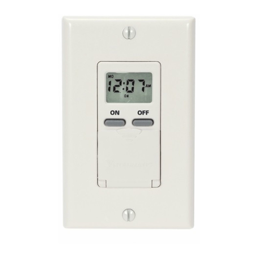
MODEL EI500 Series
Installation and User Instructions
Features
• 7-Day Control Schedule
• Up to 7 ON and 7 OFF Events per day
• Works with multiple load types including: incandescent,
compact fluorescent, HID, motors, and heaters
• Available in White, Ivory, and Light Almond
Ratings
• All Ratings 125 VAC, 60 Hz
• 15A / 1875W Resistive / Heater
• 15A, General Purpose
• 8A / 1000W Tungsten
• 8A / 1000VA Inductive / STD Ballast
• 500 VA Electronic Ballast
• 1/4 HP Motor
Leads
• Black = Line
• White = Neutral
• Red = Load
• Green = Ground
WARNING
• Turn off power at circuit breaker and test that power is off before
wiring.
• Follow local electrical codes during installation.
• Connect to copper conductors only.
NOTICE
• No user-serviceable parts.
• The internal battery requires up to 30 minutes to charge. If the
battery is not charged and power is lost, schedule information
may have to be re-configured.
Installation Instructions
1. Remove wall plate and disconnect
existing light switch.
2. Make sure both "hot" and neutral
wires are present in the junction
box. If both wires are not present,
additional wiring will be necessary
before installation can be com-
pleted.
3. Connect red timer wire to wire from
fixture using wire connector.
4. Connect black timer
wire to the "hot" (usu-
ally black or red) wire in
junction box using wire
connector.
5. Cut white
wire in
junction
box (or open splice) and
strip ½" of insulation on
both wires.
Risk of Fire or Electric Shock
Electronic
7-Day
In-Wall
Time Switch
6. Connect white timer wire to white wires in junction box
using wire connector.
7. If the wall switch you are replacing had separate grounding
conductors connected to the GREEN screw on the switch,
make sure to connect these to the green wire from the
timer with a wire connector.
8. Check that all wire connections are secure.
9. Place all wires inside junction box.
10. Fit timer into junction box and install using two (2) mount-
ing screws (furnished).
11. Reconnect the electrical power.
Setting the Clock
1. Press and HOLD the CLK (Clock) button.
2. Press the DAY button until the display shows the current
day.
3. Press the HOUR button until the display shows the current
hour.
4. Press the MIN (Minute) button until the display shows the
current minute.
Setting Programs
1. Press the PROG (Program) button once. The
display will look as shown at the right.
You will now set up the time in which you
want your device turned ON.
The number 1 in the lower left hand corner
indicates that you are now programming
EVENT 1.
2. Press the DAY button repeatedly until the display shows the
day(s) when you want the timer to turn on. The options are:
- All days of the week (MO TU WE TH FR SA SU)
- Individual days of the week (MO etc.)
- Weekdays only (MO TU WE TH FR)
- Weekends only (SA SU)
3. Press the HOUR and MIN (Minute) buttons
to set the time when you want the timer to
turn on.
4. Press the PROG (Program) button again. The
display reads as shown at the right.
Advertisement

Related Manuals for Intermatic EI500 Series


Summary of Contents for Intermatic EI500 Series
- Page 1 MODEL EI500 Series Electronic Installation and User Instructions 7-Day Features In-Wall • 7-Day Control Schedule Time Switch • Up to 7 ON and 7 OFF Events per day • Works with multiple load types including: incandescent, compact fluorescent, HID, motors, and heaters •...
- Page 2 LIMITED ONE-YEAR WARRANTY If within the warranty period specified, this product fails due to a defect in material or workmanship, Intermatic Incorporated will repair or replace it, at its sole option, free of charge. This warranty is extended to the original household purchaser only and is not transferable. This warranty does not apply to: (a) damage to units caused by accident, dropping or abuse in handling, acts of God or any negligent use;...