Table of Contents
Advertisement
Available languages
Available languages
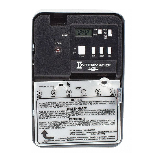
ELECTRONIC 7-DAY WATER -
HEATER TIME SWITCHES
MODELS EH10 AND EH40
WITH BATTERY CARRYOVER
RESET
ON
OFF
LOAD
Fig.1
OWNER/INSTALLER INSTRUCTION MANUAL
ATTENTION: READ CAREFULLY BEFORE ATTEMPTING
TO INSTALL YOUR INTERMATIC TIME SWITCH. FAIL-
URE TO COMPLY WITH INSTRUCTIONS COULD
RESULT IN PERSONAL INJURY AND/OR PROPERTY
DAMAGE!
RETAIN
FOR
MANUAL (MAN) - AUTOMATIC (AUTO)
(See Fig. 1)
• MANUAL: Bypasses your program completely; timer
will not resume program until you return switch to
AUTO mode position.
• AUTOMATIC: For automatically switching at ON/OFF
times; accurate to-the-minute.
PROGRAM (PROG) - RUN - TIME SET
• PROGRAM: Use this position when programming.
• RUN: Use this position for normal operation. Be sure to
return to RUN after setting time and program.
• TIME SET: Use this position to set day and time of day.
ON/OFF - EVENT (the large push button) - Serves a dual
purpose
• EVENT: Used for programming (active only when switch
is set at PROG)
• ON/OFF: Override (active only when switch is set at
RUN); turns load ON if already off or OFF if already on.
Timer automatically resumes program cycle only when
slide switch is in AUTO. Note that this button is also
accessible without opening the enclosure.
SPECIFICATIONS:
Clock Voltage - Model EH40 - 240V. A.C., 50/60 Hz
EH10 - 120V. A.C., 50/60 Hz
Power Consumption - EH10 - 1.0 W. Max. EH40 - 3.0
W. Max..
Contact Configuration - EH10 (SPST) Single pole-single
throw model- EH40(DPST) Double pole-single throw model
Switch Rating (Per Pole) -
• 30 amp inductive/resistive - 120-240V. A.C., 60 Hz
• 1 H.P. 120V. A.C., 60 Hz.
• 1-1/2 H.P. 240V. A.C., 60 Hz.
• 5 amp tungsten, 120-240V. A.C., 60 Hz.
®
MAN
PROG
RUN
AUTO
TIME
SET
EVENT
DAY HOUR MIN
®
BATTERY
FUTURE
REFERENCE.
Set Points (Events) - 12 total (6 ON/6 OFF) - Can be
assigned in any combination to weekdays, weekend days,
daily or weekly operation providing up to a maximum of 84
weekly operations (42 ON/42 OFF).
Battery Powered Clock Operation - 3 years minimum,
AA industrial grade alkaline supplied with time switch.
Minimum ON/OFF Time - 1 Minute
Maximum ON/OFF Time - 6 days 23 hours 59 minutes
Shipping Weight - 2.37 Lbs. (1.05 Kg)
Case - Drawn steel, 7-3/4" (19.7 cm) high, 5" (12.7cm)
wide, 3" (7.6 cm) deep; gray finish with lockable spring
hasp, clear see-through viewing window and external over-
ride.
Knockouts - Combination of 1/2 - 3/4" (one on back and
each side, two on bottom)
Wire Size - AWG #10 through #18
GENERAL SAFETY INFORMATION:
WARNING: DISCONNECT THE POWER TO THE TIME
SWITCH AND THE LOADS BEFORE INSTALLING THIS
TIME SWITCH.
1. Mount the time switch in the desired location using the
three mounting holes which are provided. Mount the
time switch at eye level, if possible, providing
sufficient room to the left of the enclosure for the
cover to swing open fully. (See Fig. #2). The time switch
mechanism does not need to be removed from the
enclosure to mount the time switch since the top mount-
ing hole is a slotted type mounting hole. Secure a screw
or other fastener at eye level. The head of the screw
of fastener should be slightly larger than the narrow
portion of the slotted hole to ensure that the time switch
is securely held in place. The remaining two mounting
holes provide a means to secure the time switch.
2. If you do remove the mechanism, refer to Figure #3 and
remove the mechanism from the case by depressing
the catch at the top of the case and pulling out.
CAUTION:
DO
NOT
BOARD COMPONENTS SINCE STATIC DISCHARGE
COULD DAMAGE THE MICROPROCESSOR.
Mounting Holes
Ground
Terminal
Fig.2
Knockouts
3. Replace the mechanism in the case if it has been
removed, making sure to engage ribs at sides of
mechanism between ears at sides of case before
snapping in place.
4. Lift the left side of the insulator off of the retaining post
and pivot it up and away to expose the terminal
screws.
5. Strip the supply and load wires by removing 1/2 inch of
insulation. DO NOT USE ALUMINUM WIRE. Insert
the wire ends under the proper terminal plates and
tighten the screws firmly. Use any size wire,
AWG #10 through #18. Connect ground wire to
grounding terminal at bottom of case.
6. Replace the plastic insulator.
7. Follow instructions for battery installation. Be sure that
the battery is functioning properly. This can be checked
by seeing that the display is visible. If the display
has scrambled information, check to be sure that
the polarity orientation of the battery is as shown on
the cover label, then press the RESET switch and hold
for at least two seconds. Note that the battery can
easily be replaced without removing the time
switch mechanism or field wiring. Simply press in and
downward (in the direction of the arrow) on the
battery cover which is identified with the word "Battery".
It is recommended that the battery be replaced with a
"AA" industrial grade alkaline cell at two to three
TOUCH
THE
CIRCUIT
Tilt Top Forward
Snap Out Catch
Lift Up
To
Remove
Fig. 3
Advertisement
Table of Contents

Related Manuals for Intermatic EH10


Summary of Contents for Intermatic EH10
- Page 1 SPECIFICATIONS: Clock Voltage - Model EH40 - 240V. A.C., 50/60 Hz EH10 - 120V. A.C., 50/60 Hz Power Consumption - EH10 - 1.0 W. Max. EH40 - 3.0 W. Max.. Contact Configuration - EH10 (SPST) Single pole-single throw model- EH40(DPST) Double pole-single throw model Switch Rating (Per Pole) - •...
- Page 2 • MAINTENANCE: With the exception of battery replace- ment at 2-3 year intervals, your Intermatic timer is maintenance-free. • AFTER THE INSTALLATION IS COMPLETED, THE LOCKABLE HASP SHOULD BE MOVED TO THE UP POSITION TO ENGAGE THE COVER WHEN IT IS CLOSED.
- Page 3 Tension de l’Horloge EH10 - 120 VCA, 50/60 Hz EH40 - 240 VCA, 50/60 Hz Consommation d’electricite EH10 - 1.0 Watts max. EH40 - 3.0 Watts max. Configuration des contacts Model EH10 Unipolaire/Unidirectionnel Model EH40 Bipolaire/Unidirectionnel Valeurs Nominales des Contacts (par pole) •...
- Page 4 Si ce produit s’avère défectueux en matériaux ou en fabrication dans un délai de un (1) an à compter de sa date d’achat, Intermatic Incorporated le réparera ou le remplacera gratuitement. La garantie est nulle si (a) les dommages sont attribuables aux accidents, à...
- Page 5 El temporizador reaunda el próximo ciclo automàticamente. ESPECIFICACIONES ALIMENTATION DEL TEMPORIZADOR EH10 - 1.0 Vatios Max.,120 VAC, 50/60 Hz. EH40 - 3.0 Vatios Max., 240 VAC, 50/60 Hz. CONFIGURATION DE INTERRUPTOR Model EH10 (SPST) Model EH40 (DPST) CAPACIDAD DE CARGA DEL INTERRUPTOR (POR POLO) - 30 A.
- Page 6 Si en el transcurso de UN (1) años a partir de la fecha de adquisición, este producto pre- senta algún defecto debido al material o a su fabricación, Intermatic Incorporated lo reparará o sustituirá sin coste adicional.La garantia no se aplica a: (a) daños causados por accidente, abuso, utilización incorrecta, caidas;...
- Page 7 NOTE: Jumpers can be added to supply load power for 120 V loads, see Fig. 4. For 240 V loads See Fig. 5. CAUTION: Do not use jumpers if load(s) are not 120 or 240 VAC, because the load can be damaged. Supply separate power of the correct voltage.
- Page 8 INTERMATIC INCORPORATED SPRING GROVE, ILLINOIS 60081-9698 158ET8899 - 8 -...