Table of Contents
Advertisement
Installation Date ______________________
Battery
Replacement
Recommended _______________________
(8 years after installation)
http://www.intermatic.com
Intermatic Plaza, Spring Grove, Illinois 60081-9698
Printed in U.S.A.
© Copyright 2001 Intermatic Inc.
158ET10491
Next Generation
Models ET70815CR, ET70815CR24,
ET71615CR, ET71615CR24
INSTRUCTIONS
Pg.
CHARTS
REFERENCE
Pg.
• ASTRO and Time Zones
• Typ. Wiring Configurations 31-32
Vol. 4
2
3
3
3
4
4
5-9
9
10-14
14-16
16
Pg.
17-20
21
26-27
28-30
33-36
36-38
Advertisement
Table of Contents

Related Manuals for Intermatic ET70815CR


Summary of Contents for Intermatic ET70815CR
-
Page 1: Table Of Contents
Installation Date ______________________ Battery Replacement Recommended _______________________ (8 years after installation) http://www.intermatic.com Intermatic Plaza, Spring Grove, Illinois 60081-9698 Printed in U.S.A. © Copyright 2001 Intermatic Inc. 158ET10491 Next Generation Models ET70815CR, ET70815CR24, ET71615CR, ET71615CR24 Vol. 4 INSTRUCTIONS • INTRODUCTION • LED Display •... -
Page 2: Introduction
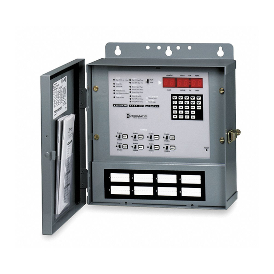
INTRODUCTION This easy to program microprocessor-based time switch provides flexible 24-hour, 7 day or full year load control. Its unique “self-prompting” feature simplifies programming by leading you through with flashing prompts. The 2 rows of LEDs on the left side flash and indicators in the digital display light while you are programming to identify information that needs to be entered. -
Page 3: Set Up
S E T U P SET UP is performed once during installation to set the internal CLOCK, ASTRO (sunrise/sunset) times and HOLIDAY references. After entering and okaying the ASTRO Zone, the timer will display calculated “center of time zone” times when prompting for sunrise and sunset entries. You may OK these, enter actual sunrise/sunset times or enter offset times for early or late ASTRO operation. - Page 4 and time, as is normal INTVL. To initiate an override interval, set the RUN/SET switch to RUN, set the switch for the desired load to Enable, press the INTVL key and hold, and press the ON/OFF button for the load you wish to override. The green load indicator flashes during the interval to show override selection.
-
Page 5: Load Controls
Holiday schedules and dates will remain in timer memory until deliberately cleared. For those Holidays whose dates vary from year to year, you must manually revise the start and stop dates (in SET UP review) annually. Holidays may not be programmed to end before their start date and must end by Dec. -
Page 6: Reviewing/Revising Data
If a soft start other than the factory setting of 15 seconds is desired press SET UP; and the date will be displayed. Then press PULSE: SS (for Soft Start) appears in the left two displays with 3 dashes in the rightmost displays. Enter the soft start desired by keying in a number from 1 to 127 seconds, and then press OK. -
Page 7: Review Special Holiday Switching Activities
REVIEW INDIVIDUAL DAY, DAY GROUP, OR COPIED ACTIVITIES • Press PROG, then press the day key (SUN/1 through SAT/7) or the day group key (wkDY/8, wkND/9 or ALL/0) to select the day or day group to review. NOTE: If you have entered data as a day group and attempt to review any of the days individually, the message “End of Review”... -
Page 8: Programming Example
• During automatic review, the OK key must be used to pause the display before the displayed data can be deleted. • After any program data is cleared, review is terminated. The timer is now in the program mode for the selected day, anticipating a new entry. -
Page 9: Battery Backup
Load slide switches to Enable Load 1and Disable 2 Press SAT/7, OK (selects Saturday only); 7, 5, 0, AM, OK (load On time); 1, 2, 0, 0, PM, OK (load Off time) Scheduled PROGRAM is now complete. Assume A 30 min. INTERVAL override duration is desired for Load 1. - Page 10 SWITCHING TIMES Day/Day CIRCUITS SWITCH ON SWITCH OFF PULSE INTVL Group 5 6 7 8 SWITCHING TIMES ASTRO Day/Day Override Group CIRCUITS SWITCH ON SWITCH OFF PULSE INTVL 9 10 11 12 ASTRO Override Next Generation...
-
Page 11: Holiday Reference
SWITCHING TIMES Day/Day CIRCUITS SWITCH ON SWITCH OFF PULSE INTVL Group 13 14 15 16 HOLIDAY REFERENCE # HOLIDAY ASTRO Override (Up to 99 holidays or holiday durations can be programmed) START Month/Date Month/Date Next Generation... -
Page 12: Holiday Switching Times
HOLIDAY SWITCHING TIMES HOLIDAY CIRCUITS SWITCH ON SWITCH OFF PULSE INTVL Ref # 1 2 3 4 NOTE: Holidays not programmed for switching times will automatically skip all load activities normally associated with the day(s) that the holiday(s) occur. HOLIDAY SWITCHING TIMES ASTRO HOLIDAY CIRCUITS SWITCH ON SWITCH OFF PULSE INTVL Override... - Page 13 HOLIDAY SWITCHING TIMES HOLIDAY CIRCUITS SWITCH ON SWITCH OFF PULSE INTVL Ref # 9 10 11 12 HOLIDAY SWITCHING TIMES ASTRO HOLIDAY CIRCUITS SWITCH ON SWITCH OFF PULSE INTVL Override Ref # 13 14 15 16 ASTRO Override Next Generation...
- Page 14 TIME ZONES After the astro zone is entered the approximate sunrise and sunset times Albuquerque for the center of the time zone will be Atlanta displayed. Depending on your location Baltimore relative to the center, you may want to Bangor, ME change (offset) this time.
-
Page 15: Special Instructions
STOP: Disconnect cable from rear of logic module by pulling straight back on the connector pull tab. Changing Power Input Voltage–Multi-volt Models ET70815CR and ET71615CR These models can be powered by any industry standard 50–60Hz AC voltage, 120 to 277 V. - Page 16 (typically into the conduit). NOTE: If your application requires more than 4 circuits of remote override, order Intermatic accessory #156ET9402A for 8 circuits of override or #156ET9403A for 16 circuits of override. Re-installing Logic Module Carefully plug the cable connector straight into the connector on the rear of the logic module.
-
Page 17: Troubleshooting
TYPICAL WIRING CONFIGURATION 24 Volt Models (ET70815CR24 shown) WARNING: Connect 24 VAC 60 Hz only to 24V timer power terminals. NOTE: To enable switching loads of a voltage different than the timer power voltage, the outputs from this timer are isolated relay contacts. You need to connect a source of power to the common (COM) terminals as shown above. - Page 18 Problem Solution(s) Load Switches • Using the REV function, check program times at Incorrect against the times you entered in the chart. Time • Review SETUP to see if the timer is following a holiday schedule. Holiday dates and sched- ules from the prior year do not automatically clear or adjust.
-
Page 19: Error Messages
Problem Solution(s) Events programmed via Day Group or Copy Day methods will not show when reviewing individual days or vice versa. Difficulty in • When using pulsed output for switching a Programming/ latching relay or contactor without “self- Reviewing On/ clearing”... - Page 20 ERR 0E Invalid or incomplete entry ERR 0F Unrecognized key ERR 1A No AM or PM selection ERR 1b Review entry not applicable ERR 1C One or more of the selected circuits has a program conflict ERR 1d The day of the week entry does not agree with the previously entered date–the date has been cleared and you must re-enter both ERR I E Out of memory...