Table of Contents
Advertisement
Quick Links
Advertisement
Table of Contents

Related Manuals for Sennheiser AC 3200-II


Summary of Contents for Sennheiser AC 3200-II
- Page 1 Active Transmitter Combiner 8:1 AC 3200-II Instruction manual...
-
Page 2: Table Of Contents
Contents Contents Important safety instructions ..................2 The AC 3200-II active transmitter combiner 8:1 ............4 Delivery includes ........................ 4 Connection diagram ......................5 Product overview ....................... 6 Putting the AC 3200-II into operation ................7 Preparing the AC 3200-II for use ..................7 Connecting devices ....................... -
Page 3: Important Safety Instructions
10. Protect the mains cable from being walked on or pinched, particularly at plugs, convenience receptacles, and the point where it exits from the device. 11. Only use attachments/accessories specified by Sennheiser. 12. Use only with the cart, stand, tripod, bracket, or table specified by the manufacturer, or sold with the device. - Page 4 “Improper use” means using the device other than as described in this instruction manual, or under operating conditions which differ from those described herein. This instruction manual is also available on the Internet at www.sennheiser.com. Manual AC 3200-II...
-
Page 5: The Ac 3200-Ii Active Transmitter Combiner 8:1
The AC 3200-II active transmitter combiner 8:1 The AC 3200-II active transmitter combiner 8:1 With the AC 3200-II active transmitter combiner, the signals of up to eight Sennheiser wireless monitoring transmitters can be combined onto a single antenna, e.g. the A 2003 UHF directional antenna, the A 1031 U omni-directional antenna or the A 5000 CP circularly polarized UHF antenna. -
Page 6: Connection Diagram
Connection diagram Connection diagram The below connection diagram shows the connections for an 8-channel system with a single antenna. AC 3200-II RF OUTPUT Rack-mount transmitters RF INPUTS RF OUTPUTS AC 3200-II... -
Page 7: Product Overview
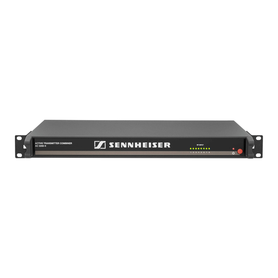
Product overview Product overview 4 5 2 ACTIVE TRANSMITTER COMBINER AC 3200-II Rack mount “ears” Air vents (on the sides) 8 LEDs: operation indicators of the RF inputs On/off switch DC input socket for connecting the NT 12-125D mains unit... -
Page 8: Putting The Ac 3200-Ii Into Operation
Never stack more than two devices directly one above the other. Never place several NT 12-125D mains units directly next to one another. To ensure that the AC 3200-II cannot slip on the surface on which it is placed, four self- adhesive soft rubber feet are supplied. - Page 9 In order to avoid heat accumulation, make sure to install the AC 3200-II as the uppermost device in the rack. Provide for a duct or vent space of 1 U above the AC 3200-II to ensure that the heated air can dissipate.
-
Page 10: Connecting Devices
Never connect the AC 3200-II to other active combiners. Only connect suitable antennas to the output of the AC 3200-II. The AC 3200-II active transmitter combiner can be used with either the A 2003 UHF directional antenna, the A 1031 U omni-directional antenna or the A 5000 CP circularly polarized UHF antenna. -
Page 11: Connecting A Transmitter To The Ac 3200-Ii
Putting the AC 3200-II into operation Connecting a transmitter to the AC 3200-II To connect a transmitter: Connect the BNC cable of the transmitter to one of the eight RF inputs RF IN 1 RF IN 8 Connecting the mains unit Connect the mains cable (EU, UK or US version, depending on your location) to the input socket on the NT 12-125D mains unit. -
Page 12: Switching The Ac 3200-Ii On And Off
The AC 3200-II switches off and the LED goes off. After switch-off, the AC 3200-II is in standby mode. To disconnect the device and the NT 12-125D mains unit from the mains power supply, pull out the mains connector from the wall socket. -
Page 13: Cleaning And Maintaining The Ac 3200-Ii
Possible cause Solution The LED does The AC 3200-II doesn’t Check if the AC 3200-II is connected not light up consume current. to the NT 12-125D mains unit, if the mains unit is connected to the mains power supply and if the on/ off switch is pressed. - Page 14 If a problem occurs that is not listed in the above table or if the problem cannot be solved with the proposed solutions, please contact your local Sennheiser partner for assistance. To find a Sennheiser partner in your country, search at www.sennheiser.com under “Service &...
-
Page 15: Specifications
Specifications Specifications AC 3200-II Frequency range 500 to 870 MHz Distribution attenuation 0 dB (±1 dB) RF input power Nominal value up to 100 mW per input Inputs protected up to max. 250 mW 50 Ω Impedance Power supply 12 V Current consumption max. -
Page 16: Manufacturer Declarations
698 MHz Manufacturer Declarations Warranty Sennheiser electronic GmbH & Co. KG gives a warranty of 24 months on this product. For the current warranty conditions, please visit our website at www.sennheiser.com or contact your Sennheiser partner. CE Declaration of Conformity 0682 •... - Page 17 • Consult the dealer or an experienced radio/TV technician for help. Changes or modifications made to this equipment not expressly approved by Sennheiser electronic Corp. may void the FCC authorization to operate this equipment. Before putting the device into operation, please observe the respective country-...
- Page 18 Sennheiser electronic GmbH & Co. KG Am Labor 1, 30900 Wedemark, Germany www.sennheiser.com Publ. 06/11, 538976/A01...