Table of Contents
Advertisement
FOR YOUR SAFETY - This product must be installed and serviced by authorized personnel, qualified inpool/spa
heater installation. Improper installation and/or operation can create carbon monoxide gas and flue gases which can
cause serious injury, property damage, or death. For indoor installations, as an additional measure of safety, Pentair
Aquatic Systems strongly recommends installation of suitable Carbon Monoxide detectors in the vicinity of this
appliance and in any adjacent occupied spaces. Improper installation and/or operation will void the warranty.
120/240 VAC NATURAL GAS/LP GAS
Models
175K BTU/HR
200K BTU/HR (A SME)
200K BTU/HR
250K BTU/HR
250K BTU/HR (HD)
250K BTU/HR (A SME)
250K BTU/HR (HD ASME)
300K BTU/HR
400K BTU/HR
400K BTU/HR (HD)
400K BTU/HR (A SME)
400K BTU/HR (HD ASME)
Rev. H 9-5-12
Natural
Propane
46 0792
460793
46 1000
461001
46 0730
460731
46 0732
460733
46 0806
–
46 0771
460772
46 1020
–
46 0734
460735
46 0736
460737
46 0805
–
46 0775
460776
46 1021
–
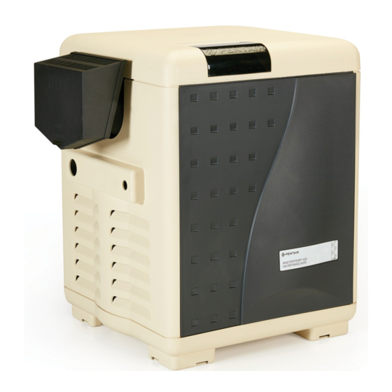
MASTERTEMP
®
Pool and Spa Heater Installation and User's Guide
Advertisement
Table of Contents
Troubleshooting

Related Manuals for Pentair Mastertemp 175K BTU/HR


Summary of Contents for Pentair Mastertemp 175K BTU/HR
- Page 1 Improper installation and/or operation can create carbon monoxide gas and flue gases which can cause serious injury, property damage, or death. For indoor installations, as an additional measure of safety, Pentair Aquatic Systems strongly recommends installation of suitable Carbon Monoxide detectors in the vicinity of this appliance and in any adjacent occupied spaces.
- Page 2 Customer Service and Tecnincal Support If you have questions about ordering Pentair Aquatic Systems replacement parts, and pool products, please call: Phone: (800) 831-7133 Fax: (800) 284-4151 (8 A.M. to 4:30 PM Eastern Time/Pacific Time) Web sites: www.pentairpool.com - www.staritepool.com MASTERTEMP ®...
-
Page 3: Table Of Contents
Contents Important Notices ....................................Warranty Information .................................... Code Requirements ....................................C onsumerInformation and Safety Information ............................6 - 9 General Specifications ..................................Heater Description ....................................Putting the H eaterinto Service ................................Specifications ...................................... Plumbing Connections ..................................Valves ........................................Manual By-Pass ....................................WaterConnections .................................... - Page 4 Fuel Type Construction HEATER IDENTIFICATION INFORMATION — (HIN) H. I. N. HEATER IDENTIFICATION NUMBER ® ID DESIGNATOR FOR PENTAIR AQUATIC SYSTEMS MASTERTEMP HEATERS Example: ASME = STANDARD MODEL CONSTRUCTION = ASME = ASME CERTIFIED MODEL HD ASME = HEAVY DUTY ASME MODEL...
-
Page 5: Important Notices
Section 2: Warning and Safety Instructions IMPORTANT SAFETY INSTRUCTIONS SAVE THESE INSTRUCTIONS ® MASTERTEMP Pool and Spa Heater IMPORTANT NOTICES WARRANTY INFORMATION CAUTION OPERATING THIS HEATER CONTINUOUSLY AT WATER TEMPERATURE BELOW 68° F. WILL CAUSE HARMFUL CONDENSATION AND WILL DAMAGE THE HEATER AND VOID THE WARRANTY. Do not use the heater to protect pools or spas from freezing if the final maintenance temperature desired is below 68°... -
Page 6: Code Requirements
CODE REQUIREMENTS DANGER CARBON MONOXIDE GAS IS DEADLY – Exhaust from this pool heater contains toxic levels of carbon monoxide, a dangerous, poisonous gas you cannot see or smell. CONSUMER INFORMATION AND SAFETY WARNING The U.S. Consumer Product Safety Commission warns that elevated water temperature can be hazardous. See below for water temperature guidelines before setting temperature. -
Page 7: Safety Information
If used outdoors, instal l far from open windows, doors, vents and other openings. Pentair strongly recommends that all vents, pipes and exhaust systems be initially and periodically testedfor proper operation. This testi n g can be accomplished by using a hand-held carbonmonoxide meter and/or by consulting with a gas professional. - Page 8 Do not attempt to alter the rated input or type of gas by changing the orifice. If it is necessary to convert to a different type of gas, consult your Pentair dealer.
-
Page 9: General Specifications
CONSUMER INFORMATION AND SAFETY WARNING The U.S. Consumer Product Safety Commission warns that carbon monoxide is an "invisible killer". Carbon monoxide is a colorless and odorless gas. GENERAL SPECIFICATIONS NOTICE: • Combustion ai r contaminated by corrosive chemical fumes can damage the heater and will void the warranty. •... -
Page 10: Heater Description
HEATER DESCRIPTION Blowe r Mixer Inlet (Cold Water) SEQUENCE OF OPERATION Outlet Bu rner (Mixed He ati ng C oils Wate r) Figure 1. PUTTINGTHE HEATER INTO SERVICE MASTERTEMP ® Pool and Spa Heater Installation and User’s Guide Rev. H 9-5-12... -
Page 11: Specifications
SPECIFICATIONS DIMENSIONS IN INCHES FRONT ELECTRICAL CONDUIT PORT EXHAUST SIDE PLUMBING SIDE Figure 2. Rev. H 9-5-12 MASTERTEMP ® Pool and Spa Heater Installation and User’s Guide... -
Page 12: Plumbing Connections
PLUMBING CONNECTIONS CAUTION PUMP POOL POOL H EATER FILTER Before operating the heater on a new installation, turn M ANUAL BY-PASS on the circulation pump and bleed all the air from the GATE VAL VE filter using the air relief valve on top of the filter. Water Figure 3. -
Page 13: Below Pool Installation
VALVES CAUTION Exercise care when installing chemical feeders so as to not allow back siphoning of chemical into the heater, filters or pump. When chemical feeders are installed in the circulation of the piping system, make sure the feeder outlet line is down stream of the heater, and is equipped with a positive seal noncorrosive “Check Valve”, (P/N R172288), between the feeder and heater. -
Page 14: Gas Connections
GAS CONNECTIONS NOTE A manual main shut-off valve must be installed externally to the heater. WARNING DO NOT INSTALL THE GAS LINE UNION INSIDE THE HEATER CABINET. THIS WILL VOID YOUR WARRANTY. 18–24" of 3/4" M anual Gas line from Sh ut-of f Valve Valve... -
Page 15: Gas Pipe Sizing
GAS PIPE SIZING Table 2. l a r c i b c i b ” 2 ” 4 ” 1 / 1 - ” 4 / 1 - ” 2 ” 2 / 1 - ” 2 ’ 0 2 ’... -
Page 16: Testing Gas Pressure/Gas Pressure Requirements
TESTING GAS PRESSURE WARNING Risk of fire and explosion. Improper installation, incorrect adjustment, alteration, service, or maintenance of the Combination Gas Control Valve can lead to fire or explosi o n, causing loss of life, personal injury, and/or property damage. If it is necessary to adjust the gas valve, this must be done by only by a qualified service agency. -
Page 17: Outdoor Installation
OUTDOOR INSTALLATION (U.S. and Canada) WARNING Risk of explosion if a unit burning propane gas is installed in a pit or other low spot. Propane is heavier than air. Do not install the heater using propane in pits or other locations where gas might coll e ct. Consult your local bui l ding code official s to determine installation requirements and specific installation restrictions of the heater relative to propane storage tanks and filling equipment. -
Page 18: Outdoor Installation Venting Guidelines
OUTDOOR INSTALLATION VENTING GUIDELINES From window or door SIDE VIEW Property Line 6 in From building wall Fo rce Ai r In le t Exhaus t Grill (Vent) Build in g Vent Termination: Must be at least 3 ft. above any forced air inlet located within a 10 ft. -
Page 19: Indoor Venting-General Requirements (C Ategory I & Category Iii - Clarification)
INDOORVENTING — General Requirements Vertical only Vertical or Horizontal HEATER CLEARANCES — General Requirements TOP ......6 in. (15 cm) EXHAUST SIDE ..6 in. (15 cm) 6 in. HEADER SIDE ....6 in. (15 cm) DOOR PANELS† ..6 in. (15 cm) 6 in.* 6 in.* 6 in. -
Page 20: Combustion Air Supply
COMBUSTION AIR SUPPLY d l i i s t d l i g n i o i t . n i . n i . n i . n i . n i . n i . n i . n i . -
Page 21: Vent Installation (Indoor Installation For U.s. Or Outdoorshelterfor Canada)
N OT E *: Vent must be at least eight (8) feet away from nearest vertical surface. Vents extending five (5) feet or more above the roof must be braced orguyed. Consult yourlocal code officialsfor detailed information. - NEGATIVE PRESSURE (See Figures 11, 12 and Cl ean th e In terio r Surface... - Page 22 Listed Termination Min. 10 Ft. Storm Collar Flashing 6" Minimum Clearance to Combustible Materials Class B Double Wall Firestop Metal Vent Pipe Metal Flue Collar Vent Support Vertical Body Vent Pipe so adapter does not take weight of pipe. WARNING Typical Metal Vent Pipe Installation - U.S.
- Page 23 WARNING Fire Hazard. Do not vent the heater directly into a masonry chimney. Installation into a masonry chimney must use a chimney liner and must meet the National Fuel Gas Code, ANSI Z223.1/NFPA 54 and/or CSAB149.1, Natural Gas and Propane Installati o n Codes requirements and all local code requirements.
-
Page 24: H Orizontal Or Vertical Venting - Positive Pressure
- POSITIVE PRESSURE (See Figures 14, 15, and NOTE Each 90-degree elbow reduces the maximum horizontal vent run by 12 feet and each 45-degree elbow in the vent run reduces the maximum vent run by 6 feet. See the table below for the maximum vent lengths using 90-degree and 45-degree elbows. - Page 25 WARNING Risk of carbon monoxide poisoning if adapter is improperly attached. Mechanical connections (such as screws) can cause cracking and leaks in the adapter. Do NOT dri l l holes or use screws to connect the appliance adapter to the heater vent body.
- Page 26 Ma x. 12" 4' Min. 4' Min. Mi n. 3" Vent Ve nt Ter min atio n Termination Ven t 4' Min. Te rminatio n 1 ' Min. 4' Min. At le ast 7 ' above gra de adjacent 1' Min imum Gas Meter to pu blic above snow or...
-
Page 27: Outdoorshelter Vent Installation
OUTDOOR SHELTER INSTALLATION WARNING Risk of asphyxiation if exhaust is not correctly vented. Follow venting instructions exactly when installi n g heater. Do not use a draft hood with this heater, as the exhaust is under pressure from the burner blower and a draft hood will allow exhaust fumes to blow i n to the room housing the heater. -
Page 28: Control Panel Indexing
To p P an el D oor A ccess P an el Doo r AccessP ane l Figure 19. For Heater mounting bolts and clamps, purchase separately Bolt Down Bracket Kit, Part No. 460738. L ead An ch or MASTERTEMP ®... -
Page 29: Electrical Connections
ELECTRICAL CONNECTIONS CAUTION This heater is designed to operate at 120 or 240 VAC. It is not recommended to be connected to OR operate on a 208 VAC. NOTE • Before making any electrical connections to the power supply, remove the access door panel s , open the control box and pl u g in the correct plug (120 volt or 240 volt). -
Page 30: Fireman'sswitch Connection/Remote Controlconnections
CONNECTION OF FIREMAN’S SWITCH OR REMOTE CONTACT CAUTION If, while there is line voltage connected to the heater, you touch either line voltage terminal with any 24VAC wire that is connected to the control board (including the Fireman’s Switch jumper), you will immediately destroy the control board and void the warranty. -
Page 31: Mastertemp Heaterwiring Diagram
MASTERTEMP HEATERWIRING DIAGRAM CONNECTION DIAGRAM AGS Switch Air Flow Swi tch Stack Flu e Sensor Extra Switch 1 Gas Valve Hi -L imi t Switch Pressure Switch NA/LP Models Only E S1 OPER ATING CONTROL External C ontrol Interface Circuit Disabled, Heater Membrane Pad Enabled Spa Line CommonLine... -
Page 32: Electrical Schematic Ladderd Iagram
MASTERTEMP HEATER ELECTRICAL SCHEMATIC LADDER DIA- GRAM LADDER DIAGRAM 12 0/24 0 IGN ITER BLOWER 12 0/240 CL ASS II TRANSFORMER 2 4 VAC OP ERATING CONTROL 2 4 VAC 24 VAC GN D FLOW LOGIC 2 4V SWITCH WATER PRESS URE LIMIT SWITCH... -
Page 33: Basic System Operation
Operation Instructions BASIC SYSTEM OPERATION MASTERTEMP HEATER HSI ELECTRONIC IGNITION LIGHTING/OPERATION WARNING START-UP AND SHUTDOWN INSTRUCTIONS ARE ON THE LABEL ATTACHED TO THE COVER OF THE APPLIANCE CONTROL BOX. Rev. H 9-5-12 MASTERTEMP ® Pool and Spa Heater Installation and User’s Guide... -
Page 34: Operating
OPERATING INSTRUCTIONS Water Pressure Swit ch Figure 25. Gas control is shown OFF. Push toggle switch away from you to switch ON. here. Figure 26. TOTURN OFF GAS TO APPLIANCE MASTERTEMP ® Pool and Spa Heater Installation and User’s Guide Rev. -
Page 35: Safety Controls
SAFETY CONTROLS Figure 27. Air F low Sw itch WARNING Hazardous pressure. Do not bypass the Water Pressure Switch or render Figure 28. it inoperable. Water Pressure Switch Tu rn star w he el clock wis e to ra is e p re ssu re se t p oi nt if pr ess ure swi tc h is m ore th an 4 fe e t (1 .2M) b el ow wa ter le vel Star Wheel... - Page 36 SAFETY CONTROLS, (cont’d.) Diagnostic LED Flame Current 1 Flash - Air Flow Fault Check Point 2 Flashes - Flame No Call for Heat 3 Flashes - Ignition Lockout OPERATINGTHE CONTROL PANEL Figure 30. POOL ON Temperature Digi tal Temperature Up and Down Disp lay SPA ON HEATER OFF...
- Page 37 TEMPERATURE SETTING MAXIMUM TEMPERATURE SET POINT Top Panel Door Access Panel Max. Temp. Set Point POOL ON TEMP TEMP D oor POOL ON Access Panel SPA ON Figure 32. Max.Temp. Set Point TEMP TEMP SPA ON Max.Temp. Set Point Figure 33. Rev.
-
Page 38: Initial Troubleshooting And Troubleshooting Chart
Initial Troubleshooting Only qualified, trained service technicians with appropriate test equipment should service the heater. Remember that all parts of the system affect heater operation. Before starting this troubleshooting procedure, make sure that the pump is running correctly, that there are no blockages in the system, that the valves are correctly set and that the time clock is corre ctly set and is running. -
Page 39: Heater Will Not Fire Troubleshooting
Heater Will Not Fire - A Start De press “POO L” or “S PA” ON Heater shou ld fir e on de ma nd Y ES Is g reen “S PA ” o r butto n on Membra ne Pa d. for hea t. - Page 40 Heater Will Not Fire - B Start Increase POOL/SPA tempera- Is red “SERVICE Is red “SERVICE SYSTEM” ture setting on Membrane HEATER” LED “on” LED on? Pad above actual water tem- perature. Heater should fire on demand for heat. If not, Verify that pump is on, filter is and no other red LED’s light, not blocked, and the water...
- Page 41 Heater Will Not Fire - C Start Is “SERVICE HEATER” LED Go to “INITIAL “on”? TROUBLESHOOTING” Turn off power to heater for 5 seconds, Continue to observe heater and turn back on. for several minutes. Cycle Make sure tempera- heater on and off several ture setting is above times.
- Page 42 Heater Will Not Fire - D IMPORTANT! READ ME FIRST! IMPORTANT! READ ME FIRST!! If your heater is correctly connected to 240 Volts AC, the meter will read either 0 VAC or 240 VAC. If your ICM is good, your meter will read some voltage between 0 and Ignition Control Module (ICM) will convert the 240VAC to an intermittent pulse to the ignitor.
-
Page 43: Led Diagnostics
Diagnostic LED's: AGS, AFS, HLS, PS, THERMISTOR Verify th at wate r flow rate is Se rvice pump and filter to AGS or HLS "on" above minimum requ ired fo r re store proper flow. After ser- heater. vicing, verify prop er operation Repl ace High Limit of Pressu re Switch (PS). - Page 44 Diagnostic LED's: SFS SFS "on" Ch eck Hea t Exchan ger Co il fo r leaks, limin g, soot, or low flow. He ater starts a nd run s O K, but temperature of e xh aust climbs to 45 0˚–5 00˚ in 3–5 Ch eck Thermal minutes.
-
Page 45: Burner / Heat Exchanger Troubleshooting
Burner Troubleshooting SYMPTOM CAUSE REMEDY Loud, high-pitched whine Flame is too rich. Verify pressure tap between gas valve and blower inlet. See page 16 and verify that t he gas regulator setting is –0.2" (–0.5cm) wc. Contact a qualified technician or service agency to replace the gas orifice. -
Page 46: Care And Maintenance
CARE AND MAINTENANCE WARNING Risk of fire or explosion from flammable vapors. Do not store gasoline, cleaning fluids, varnishes, paints, or other vol a tile flammabl e liquids near heater or in the same room wi t h heater. PRESSURE RELIEF VALVE (NOTFACTORY INSTALLED) REMOVE PLUG;... -
Page 47: After Start-Up
AFTER START-UP WARNING Fire or flooding hazard. If the unit overheats and the burner fail s to shut off, foll o w instructions under “To Turn Off Gas to the Appliance”, page 34, and call a qualified service technici a n to repair unit. CAUTION •... -
Page 48: Maintaining Pool Temperature
CHEMICAL BALANCE CAUTION Heat exchanger damage resulting from chemical imbalance is not covered by the warranty. WHAT A DISINFECTANT DOES WHAT IS A DISINFECTANT RESIDUAL? MASTERTEMP ® Pool and Spa Heater Installation and User’s Guide Rev. H 9-5-12... -
Page 49: Energy Saving Tips
CHEMICAL BALANCE, (cont’d.) If pH becomes too high (over alkaline), it has these effects: If pH is too low (over acid) the following conditions may occur: ALKALINITY High or Low: WATER CHEMISTRY PARAMETERS Table 12. Disinfectant levels Minimum Ideal Maximum Free Chlorine, ppm 2.0-4.0 Combined Chlorine, ppm... -
Page 50: Replacement Parts
Water System parts breakdown (Key Nos. 8 through 9), see Page 52 Repair Parts are available from your Pentair dealer. If your dealer cannot supply you, call Customer Support at 1-800-831-7133. MASTERTEMP ® Pool and Spa Heater Installation and User’s Guide... - Page 51 MASTERTEMP HEATER REPLACEMENT PARTS Rev. H 9-5-12 MASTERTEMP ® Pool and Spa Heater Installation and User’s Guide...
- Page 52 MASTERTEMP HEATER REPLACEMENT PARTS REPAIR PARTS – BURNER SYSTEM Model Part 175NA 200NA 250NA 300NA 400NA Qty. Description 175LP 200LP 250LP 300LP 400LP Combination Gas Control Valve Kit 42001-0051S 42001-0051S 42001-0051S 42001-0051S 42001-0051S 3/4" Union 38404-4097S 38404-4097S 38404-4097S 38404-4097S 38404-4097S Gas Orifice Gas Orifice O-Ring •...
- Page 53 MASTERTEMP HEATER REPLACEMENT PARTS (NA , LP Ser ie s) Kit (NA - H D Ser ies) ub e She et Coi l / C omb ustio n Ch amb er Ki t (A SME SERIES) Bro nze H ea de r - Ke y Nos. 3-1 2, 15 , 20 -22 , 4 60 94 1 4 60 94 0 4 72 73 2Z...
- Page 54 MASTERTEMP HEATER REPLACEMENT PARTS REPAIR PARTS – ELECTRICAL SYSTEM M ode l K ey Par t 1 75 NA - 200 NA 25 0N A 300 NA 4 00 NA D es cr ipt ion Qty. 17 5LP - 20 0LP 2 50 LP 3 00LP 40 0LP...
- Page 55 NOTES Rev. H 9-5-12 MASTERTEMP ® Pool and Spa Heater Installation and User’s Guide...
- Page 56 MASTERTEMP ® Pool and Spa Heater Installation and User’s Guide Rev. H 9-5-12...