Table of Contents
Advertisement
Quick Links
SPEAKER SYSTEM
[Side]
245
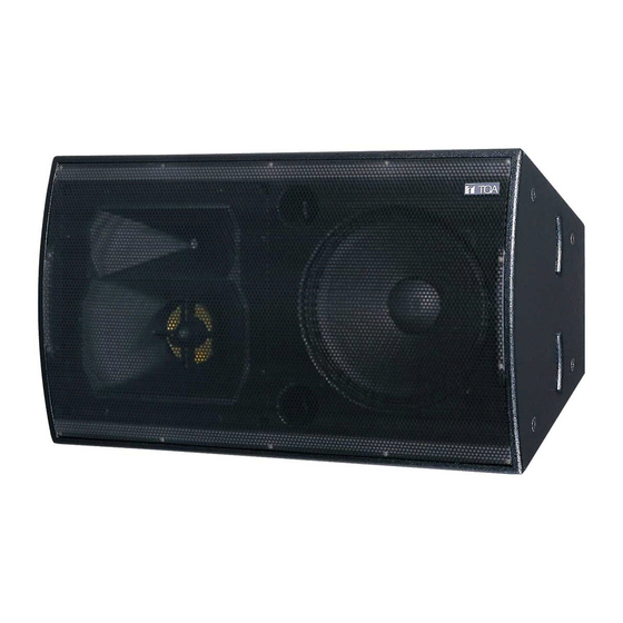
This figure is for the ES-5071-95. Note that the ES-5071-65 differs in horn size.
Please follow the instructions in this manual to obtain the optimum results from this unit.
We also recommend that you keep this manual handy for future reference.
[Rear]
[Top]
16-M12 nuts
[Front]
Gravity position
17.5°
OPERATING INSTRUCTIONS
83.5
186
480
942
ES-5071-95
ES-5071-65
Gravity position
Unit: mm
Advertisement
Table of Contents

Related Manuals for Toa ES-5071-95


Summary of Contents for Toa ES-5071-95
-
Page 1: Operating Instructions
17.5° Unit: mm This figure is for the ES-5071-95. Note that the ES-5071-65 differs in horn size. Please follow the instructions in this manual to obtain the optimum results from this unit. We also recommend that you keep this manual handy for future reference. -
Page 2: Table Of Contents
TABLE OF CONTENTS 1. SAFETY PRECAUTIONS ................3 2. GENERAL DESCRIPTION ................4 3. FEATURES ......................4 4. INSTALLATION ....................5 5. INPUT CONNECTORS ..................6 6. WIRING DIAGRAM ................... 6 7. CONNECTIONS 7.1. Single-Amplification System ................7 7.2. Dual-Amplification System ................7 7.3. -
Page 3: Safety Precautions
TOA dealer. Make no further attempt to operate the unit in this condition as this may cause fire or electric shock. -
Page 4: General Description
• The speaker's new horn pattern control corrects the inherent tendency of conventional constant directivity horns to narrow oblique radiation patterns. • The horn's directivity angle is set for 90° horizontal x 50° vertical (ES-5071-95) over short distances, and 60° horizontal x 50° vertical (ES-5071-65) over long distances. -
Page 5: Installation
4. INSTALLATION Refer all installation work to the dealer from whom the speaker was purchased. Installation requires extensive technical knowledge and WARNING experience. The speaker may fall off if incorrectly installed, resulting in possible personal injury. When installing, mounting brackets of the type suited to the conditions of the installation place must be prepared. -
Page 6: Input Connectors
5. INPUT CONNECTORS • Input connectors are located on the rear panel as shown below: Neutrik NL4MP connector Screw terminal • For connections of the NL4MP and screw terminals in each amplification system, refer to the table below: Single amplification Dual amplification Triple amplification Neutrik NL4MP... -
Page 7: Connections
7. CONNECTIONS 7.1. Single-Amplification System ES-5071-95, ES-5071-65 Power amplifier INPUT 1 INPUT 7.2. Dual-Amplification System ES-5071-95, ES-5071-65 DP-0204 (SR) Power amplifier INPUT 1 INPUT MID & HIGH INPUT 2 7.3. Triple-Amplification System DP-0204 (SR) Power amplifier ES-5071-95, ES-5071-65 INPUT 1... -
Page 8: Selection Of Multi-Amplification Drive System
8. SELECTION OF MULTI-AMPLIFICATION DRIVE SYSTEM Use the three rear panel mode switches to select the desired drive mode. Loosen the switch panel mounting screws to operate the mode switches. Set the switches as shown below depending on the drive system used, then retighten the mounting screws to secure the switch panel. -
Page 9: Multi-Amplification Processor Settings
9. MULTI-AMPLIFICATION PROCESSOR SETTINGS When using TOA's digital signal processor in conjunction with multiple amplifiers to drive the speaker, perform the following settings for the processor. 9.1. Dual-Amplification System Horizontal Installation Vertical Installation Channel Gain Polarity Filter Delay Gain Polarity... -
Page 10: Changing Horn Directivity Angle
10. CHANGING HORN DIRECTIVITY ANGLE Mid-range and high-range horns can be rotated in 90 ° steps. Use this function when switching from horizontal to vertical installation or when lining up two speakers symmetrically. Follow the procedures below to rotate the horns. -
Page 11: Speaker Unit Replacement
11. SPEAKER UNIT REPLACEMENT Follow the procedures below to replace the speaker unit: 1. Remove all 17 screws (M5x40) holding the rear cover in place, and detach the rear cover. 2. Detach the speaker cable from each speaker unit. Speaker unit 3. -
Page 12: Specifications
12. SPECIFICATIONS • ES-5071-95 Enclosure Bass-reflex type Permissive Input Continuous program, Full range: 600 W, Mid-/high-range: 360 W, Low-range: 600 W, Mid-range: 450 W, High-range: 120 W Rated Impedance Full range: 8Ω, Mid-/high-range: 8Ω, Low-range: 8Ω, Mid-range: 8Ω, High-range: 8Ω...