Table of Contents
Advertisement
• Important operating and
maintenance instructions
included.
WARNING: If the information in these
instructions is not followed exactly, a fire
or explosion may result causing property
damage, personal injury, or death.
• Do not store or use gasoline or other flammable
vapors and liquids in the vicinity of this or any
other appliance.
• What to do if you smell gas
- D o n o t t r y t o l i g h t a n y a p p l i a n c e .
Do not touch any electrical switch. Do not
use any phone in your building.
- Immediately call your gas supplier from a
neighbor's phone. Follow the gas supplier's
instructions.
- If you cannot reach your gas supplier, call the
fire department.
• Installation and service must be performed by
a qualified installer, service agency, or the gas
supplier.
Installation and service of this appliance should be
performed by qualified personnel. Hearth & Home
Technologies suggests NFI certified or factory-trained
professionals, or technicians supervised by an NFI
certified professional.
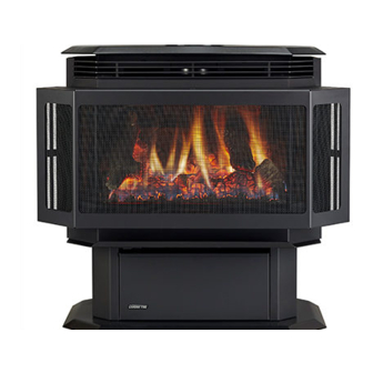
HUDSON BAY
DIRECT VENT GAS APPLIANCE
Owner's Manual
Installation and Operation
Model:
HUDBAY-FS
CAUTION
DO NOT DISCARD THIS MANUAL
• Read, understand and
follow these instructions
for safe installation and
operation.
Quadra-Fire • Hudson Bay • 7003-121_R19 • 7/14
• Leave this manual with
party responsible for use
and operation.
!
HOT SURFACES!
Glass and other surfaces are hot during
operation AND cool down.
Hot glass will cause burns.
• Do not touch glass until it is cooled
• NEVER allow children to touch glass
• Keep children away
• CAREFULLY SUPERVISE children in same room as
fireplace.
• Alert children and adults to hazards of high temperatures.
High temperatures may ignite clothing or other flammable
materials.
• Keep clothing, furniture, draperies and other flammable
materials away.
In the Commonwealth of Massachusetts:
• installation must be performed by a licensed plumber or gas
fitter.
See Table of Contents for additional Commonwealth of
Massachusetts requirements.
This appliance may be installed as an OEM installation in
manufactured home (USA only) or mobile home and must be
installed in accordance with the manufacturer's instructions and
the manufactured home construction and safety standard, Title
24 CFR, Part 3280 or Standard for Installation in Mobile Homes,
CAN/CSA Z240MH.
This appliance is only for use with the type(s) of gas indicated
on the rating plate.
R
O-T L
Tested and
Portland
Listed by
Oregon USA
C
US
OMNI-Test Laboratories, Inc.
WARNING
Advertisement
Table of Contents

Related Manuals for Quadra-Fire HUDSON BAY HUDBAY-FS


Summary of Contents for Quadra-Fire HUDSON BAY HUDBAY-FS
-
Page 1: Installation And Operation
Installation and service of this appliance should be 24 CFR, Part 3280 or Standard for Installation in Mobile Homes, performed by qualified personnel. Hearth & Home CAN/CSA Z240MH. Technologies suggests NFI certified or factory-trained professionals, or technicians supervised by an NFI This appliance is only for use with the type(s) of gas indicated certified professional. on the rating plate. Quadra-Fire • Hudson Bay • 7003-121_R19 • 7/14... - Page 2 Welcome to the Quadra-Fire Family Hearth & Home Technologies welcomes you to our tradition Each appliance is meticulously fabricated and gold and of excellence! In choosing a Quadra-Fire appliance, you nickel surfaces are hand-finished for lasting beauty and have our assurance of commitment to quality, durability, and enjoyment. Our pledge to quality is completed as each performance.
-
Page 3: Table Of Contents
B. Vent Components Diagram .......42 Section 6: Gas Information C. Vent Components List ........44 A. Fuel Conversions ..........22 D. Service Parts List ..........45 B. Gas Pressures ...........24 E. Warranty ............48 C. Gas Connection.. ..........25 F. Contact Information ...........50 = Contains updated information. Page 3 Quadra-Fire • Hudson Bay • 7003-121_R20 • 11/14... -
Page 4: Section 1: Listing And Code Approvals
Do NOT use this appliance if any part has been under water. of local codes, with National Electric Code ANSI/NFPA Immediately call a qualified service technician to inspect the 70-latest edition or the Canadian Electric Code CSA unit and to replace any part of the control system and any C22.1. gas control which has been under water. • A 110-120 VAC circuit for this product must be protected with ground-fault circuit-interrupter protection, in compliance with the applicable electrical codes, when it is installed in locations such as in bathrooms or near sinks. Page 4 Quadra-Fire • Hudson Bay • 7003-121_R20 • 11/14... -
Page 5: H. Requirements For The ......................................... Commonwealth Of Massachusetts . ...........5
Connection section additional less than one-half (1/2) inch in size, “GAS VENT DIRECTLY Commonwealth of Massachusetts requirements. BELOW. KEEP CLEAR OF ALL OBSTRUCTIONS.” Page 5 Quadra-Fire • Hudson Bay • 7003-121_R20 • 11/14... -
Page 6: Section 2: Getting Started
Getting Started A. Design & Installation Considerations C. Inspect Appliance & Components Quadra-Fire direct vent gas appliances are designed to WARNING operate with all combustion air siphoned from outside of the building and all exhaust gases expelled to the outside. No additional air source is required. Inspect appliance and components for damage. Damaged parts may impair safe operation. CAUTION • Do NOT install damaged components. • Do NOT install incomplete components. Check building codes prior to installation. -
Page 7: Selecting Appliance Location
Some carpet materials may be sensitive to radiant heat from Odor Risk. the appliance causing discoloration or odor. Tipping Risk • Install appliance on a stable, level platform/ NOTE: Flooring beneath appliance may reach 90 degrees floor strong enough to support appliance plus room ambient temperature. Check with flooring without tipping. manufacturer for maximum temperature allowed on flooring • USE wood flooring, ceramic tile, brick hearth surfaces. or high pressure laminate flooring applied directly over the sub-flooring material. Page 7 Quadra-Fire • Hudson Bay • 7003-121_R20 • 11/14... -
Page 8: Vent Termination Minimum Clearances
In a staggered installation with both gas and wood or fuel oil terminations, the wood or fuel oil termination cap must be higher than the gas termination cap. Figure 4.2 Multiple Vertical Termination Page 8 Quadra-Fire • Hudson Bay • 7003-121_R20 • 11/14... - Page 9 2. All mechanical air intakes within 10 feet of a termination cap must be a minimum of 3 feet below the Quadra-Fire assumes no responsibility for the improper perfor- termination cap. 3. All gravity air intakes within 3 feet of a termination cap mance of the appliance when the venting system does not meet must be a minimum of 1 foot below the termination cap.
-
Page 10: Section 5: Vent Information
Explosion Risk. • Pipe measurements are from center line to center line. Asphyxiation Risk. • Horizontal terminations are measured to the outside of Do NOT connect this gas appliance to a chimney the mounting surface (flange of termination cap). See flue serving a separate solid-fuel or gas burning Figure 4.1 on page 8. appliance. • Vent this appliance directly outside. • Vertical terminations are measured to the top of the last pipe before termination cap. • Use separate vent system for this appliance. May impair safe operation of this appliance or • Horizontal pipe installed level with 1/4 in. rise. other appliances connected to the flue. Page 10 Quadra-Fire • Hudson Bay • 7003-121_R20 • 11/14... -
Page 11: How To Use The Vent Graph
EX. 2 VERTICAL DISTANCE FROM APPLIANCE TO TO THE 90° ELBOW EX. 1 11" 2' 14' 15' (MIN) (MAX) Figure 5.2 TOTAL HORIZONTAL RUN TO OUTSIDE OF ExTERIOR WALL (INCLUDING ELBOWS) Page 11 Quadra-Fire • Hudson Bay • 7003-121_R20 • 11/14... -
Page 12: Horizontal Termination
Remember to include wall thickness in minimum clearances when figuring the measurements for your installation needs. Note: Direct vent pipe is designed to slide straight onto the male ends of adjacent pipes and fittings by orienting the pipe indentations so they match and slide into the entry slots on the male ends, see Figure 5.4. Push the pipe sections completely together, then twist-lock one section clockwise approximately one-quarter turn, until the two sections are fully locked. The female locking lugs may not be visible from the outside, on the pipe or fittings. They may be located by examining the inside of the female ends. Page 12 Quadra-Fire • Hudson Bay • 7003-121_R20 • 11/14... - Page 13 HHW2 of non-hardening mastic around its outside edges, so as to on a building with vinyl siding, a vinyl siding standoff make a seal between it and the wall, attach termination cap should be installed between the vent cap and the exterior to the exterior wall with the four wood screws provided. The wall (Figure 5.8, on the next page). Attach the vinyl siding arrow on the vent cap should be pointing up (Figure 5.6). standoff to the horizontal termination cap. The vinyl siding standoff prevents excessive heat from possibly melting the vinyl siding material. The vent termination cap shall not be recessed into a wall or siding. Remove siding from the area where the standoff will be located. Page 13 Quadra-Fire • Hudson Bay • 7003-121_R20 • 11/14...
- Page 14 SHEET METAL SCREW WALL WALL THIMBLE COVER/CEILING THIMBLE FIRESTOP AS REQUIRED BY LOCAL JURISDICTION STRAP Figure 5.9 Note: The attachment from the vent pipe to the vent termination cap must be sealed with silicone. Termination caps shall not be recessed into a wall or siding. Page 14 Quadra-Fire • Hudson Bay • 7003-121_R20 • 11/14...
-
Page 15: Vertical Termination
(as WALL STRAP specified by vent graph, on page 11). WARNING WALL STRAP TWO 45 DEGREE Fire Risk. ELBOWS Explosion Risk. Maintain vent clearance to combustibles as specified. • Do not pack air space with insulation or other materials. Figure 5.12 Failure to keep insulation or other materials away from vent pipe may cause fire. Page 15 Quadra-Fire • Hudson Bay • 7003-121_R20 • 11/14... - Page 16 Slip the flashing over the pipe section(s) protruding through the roof. Secure the base of the flashing to the roof with roofing nails. Ensure the roofing material overlaps the top Figure 5.15 edge of the flashing as shown in Figure 5.14. Verify that the chimney is the required height above the roof. See roof pitch table, Figure 4.3 on page 8. Page 16 Quadra-Fire • Hudson Bay • 7003-121_R20 • 11/14...
- Page 17 • Any occupied areas above the first floor, including closets and storage spaces, which the vertical vent passed through must be enclosed. The enclosure may be framed and sheet rocked with standard construction materials; however, refer to these installation instructions for the minimum allowable clearance between the outside of the vent pipe and the combustible surfaces of the enclosure. Do not fill any of the required air space with insulation. Page 17 Quadra-Fire • Hudson Bay • 7003-121_R20 • 11/14...
- Page 18 Using tin snips, cut the support box from the top corners down to the roof line, and fold the resulting flaps over the roof sheathing (Figure 5.18). Before nailing it to the roof, TRIM COLLAR run a bead of non-hardening mastic around the top edges of the support box to make a seal between it and the roof. Clean out any combustible material from inside the support box. Step 5. Assemble the desired lengths of pipe and elbows necessary to reach from the appliance up through the round support box. Ensure that all pipe and elbow connections are in their CATHEDRAL fully twist-locked position. Assemble as instructed. CEILING SUPPORT SCREWS Figure 5.19 Page 18 Quadra-Fire • Hudson Bay • 7003-121_R20 • 11/14...
- Page 19 Push the flex pipe back up into the ceiling support box, Flex center the retro connector, and attach it to the support box Pipe with sheet metal screws. Sheet Metal Screws Step 7. The connection between the appliance and the retro connector may be completed with sections of direct vent pipe. Figure 5.21 Page 19 Quadra-Fire • Hudson Bay • 7003-121_R20 • 11/14...
-
Page 20: Existing Masonry Chimney
If the hole is framed a wall thimble is Step 6. Feed the flex liner through the flashing into the chimney. required. This allows the retro connector to mount directly on the masonry and provide the correct clearances to Carefully feed the flex liner down the chimney to the bottom combustibles (Figure 5.25). and out the opening in the masonry wall, forming an angle to line up the flex liner with the vent opening on the appliance. Page 20 Quadra-Fire • Hudson Bay • 7003-121_R20 • 11/14... - Page 21 FOUR MASONRY BOLTS (NOT INCLUDED) Figure 5.30 Step 11. The connection between the appliance and the retro connector may be completed with sections of direct vent pipe. FLASHING Figure 5.28 Page 21 Quadra-Fire • Hudson Bay • 7003-121_R20 • 11/14...
-
Page 22: Section 6: Gas Information
Remove the 2 nuts that secure the burner pan to the burner support with the ratchet and socket. Burner support screws locations - Slide the burner support to the left to access the Figure 6.4 orifice. Page 22 Quadra-Fire • Hudson Bay • 7003-121_R20 • 11/14... -
Page 23: Valve Regulator Replacement
Ensure that the rubber gasket (D) is properly Figure 6.9 - positioned and install the new HI/LO pressure regulator assembly to the valve using the new screws (E) supplied with the kit. Tighten screws securely. (Reference torque = 25 in./lb.) Install the enclosed identification label (F) to the valve body where it can be seen. Fill out the conversion label and attach it to the valve cover. Page 23 Quadra-Fire • Hudson Bay • 7003-121_R20 • 11/14... -
Page 24: Gas Pressures
Pressure requirements for appliance are shown in the table below. PRESSURE Minimum Inlet Pressure 4.5 inches w.c. 11.0 inches w.c. Maximum Inlet Pressure 7.0 inches w.c. 14.0 inches w.c. Manifold Pressure on “HI” 3.5 inches w.c. 10.0 inches w.c. If the pressure is not sufficient, ensure: 1. The piping used is large enough. 2. The supply regulator is adequately adjusted. 3. That the total gas load for the residence does not exceed the amount supplied. The supply regulator (the regulator that attaches directly to the residence inlet or to the propane tank) should supply gas at the suggested input pressure listed above. Contact the local gas supplier if the regulator is at an improper pressure. Page 24 Quadra-Fire • Hudson Bay • 7003-121_R20 • 11/14... -
Page 25: Gas Connection
If flex gas lines are not approved in your area, you must changing the existing burner orifice to a smaller size. Input connect a hard pipe to the gas hookup. rate should be reduced by 4% for each 1000 feet above a You must supply a manual shut-off valve in a visible location 2000 foot elevation in the U.S.A. If the heating value of the within 3 feet (914mm) of the appliance. gas has been reduced, these rules do not apply. To identify the proper orifice size, check with the local gas utility. WARNING If installing this appliance at an elevation above 4500 feet (in Canada), check with local authorities. Fire or Explosion Hazard • Gas build-up during line purge may ignite. • Purge should be performed by qualified technician. • Ensure adequate ventilation. • Ensure there are no ignition sources such as sparks or open flame. Page 25 Quadra-Fire • Hudson Bay • 7003-121_R20 • 11/14... -
Page 26: Section 7: Electrical Information
4. Use low resistance thermostat wire for wiring from ignition system to the wall switch and thermostat. 5. Use the following chart for wire sizing. Wire Size Max. Length 16 gauge 65 feet 18 gauge 40 feet 20 gauge 25 feet 22 gauge 18 feet 6. Keep wire lengths as short as possible by removing any excess wire length. 7. Low voltage and 110 VAC voltage cannot be shared within the same wall box. Page 26 Quadra-Fire • Hudson Bay • 7003-121_R20 • 11/14... - Page 27 (711 MM) ON/OFF SWITCH RED 28 IN. VALVE (711 MM) Figure 7.1 CAUTION CAUTION Label all wires prior to disconnection when servicing controls. Shock hazard. Wiring errors can cause improper and dangerous operation. • Replace damaged wire with type 105 rated wire. Verify proper operation after servicing. • Wire must have high temperature insulation. Page 27 Quadra-Fire • Hudson Bay • 7003-121_R20 • 11/14...
-
Page 28: Remove Shipping Materials
Rotate the door forward approximately 1-1/2 in. (38mm). it into place on the right hand side. Reinsert and tighten the Holding the ashlip, lift the door up off of the stationary screws previously removed. latches and away from the appliance. Use a soft cloth and a window cleaning solution to clean all fingerprint oils from the gold or nickel surface of crown PRIOR to lighting the appliance. Page 28 Quadra-Fire • Hudson Bay • 7003-121_R20 • 11/14... -
Page 29: Grille Installation
E. Brick Set Installation Pilot Shield Pilot Bracket Keeping the baffle elevated with your hand, put Figure 8.8 - the right side brick into position. Rest the baffle on the rights side brick. The pilot shield has to be removed to install or Figure 8.6 - remove the brick refractory. Removal of the bracket requires removing two screws. Still holding the baffle in place, install the left Figure 8.9 - brick into position. Page 29 Quadra-Fire • Hudson Bay • 7003-121_R20 • 11/14... -
Page 30: Positioning The Logs
Figure 8.14 - Rear brick retainers are part of the burner pan and are numbered for reference only. NOTE: For the Hudson Bay Free Standing the Figure 8.12 - upper rear brick retainer is used. Reinstall the pilot shield with the screws removed in Figure 8.6. The pilot shield must be in place before operation of Install the left rear log (#3) over the locator pins Figure 8.15 - appliance. in the burner pan. Page 30 Quadra-Fire • Hudson Bay • 7003-121_R20 • 11/14... -
Page 31: Mineral Wool
Install the right rear log (#4) over the locator Figure 8.16 - pins in the burner pan. Place individual pieces of embers in front of and Figure 8.19 - around the gas logs where they can be seen. Space them so that gas can contact them on all sides. Avoid stacking the embers on top of each other. NOTE: Do not block gas ports. Install the right twig (#5) over the locator pins in Figure 8.17 - the right rear log and the right front log. Install the left twig (#6) over the locator pins in Figure 8.18 - the right rear log and the left front log. Page 31 Quadra-Fire • Hudson Bay • 7003-121_R20 • 11/14... -
Page 32: Blower Installation
Install the new blower by slipping grommets Figure 8.22 - over studs on the blower bracket. Reinstall the blower and bracket. Connect the wires. Install screws. Restore power to the appliance. Thermal Disk Fan Speed Control F = Female spade connector M = Male spade connector Power Cord (110 VAC) Ground Strain Relief Bushing Fan Assembly Figure 8.23 Blower Wiring Diagram Page 32 Quadra-Fire • Hudson Bay • 7003-121_R20 • 11/14... -
Page 33: Damper Adjustment
Figure 8.25 - appliance, on the right side. To adjust the shutter, loosen the wingnut. Retighten the wingnut after adjustment. Moving the shutter bolt to the right closes the shutter. Moving the shutter bolt to the left, will open the shutter. Opening the shutter causes flames to become shorter and blue. Closing the shutter creates taller orange/yellow flames. NOTE: Do not close so much as to cause a sooty flame. Improper adjustment can cause sooting in the firebox and/ or on the outside of a house with a horizontal termination. After adjustment, tighten nut to lock in place. Page 33 Quadra-Fire • Hudson Bay • 7003-121_R20 • 11/14... -
Page 34: Section 9: Operating Instructions
• Keep children away • CAREFULLY SUPERVISE children in same room as fireplace. • Alert children and adults to hazards of high temperatures. High temperatures may ignite clothing or other flammable materials. • Keep clothing, furniture, draperies and other flammable materials away. Page 34 Quadra-Fire • Hudson Bay • 7003-121_R20 • 11/14... -
Page 35: Lighting Appliance
1. Set the thermostat to lowest setting. 2. Turn off all electric power to the appliance if service is to be performed. 3. Push in gas control knob slightly and turn clockwise to "OFF" position. Page 35 Quadra-Fire • Hudson Bay • 7003-121_R20 • 11/14... -
Page 36: After Appliance Is Lit
Blue flames This is a result of normal operation and the flames will begin to yellow as the appliance is allowed to burn for 20 to 40 minutes. Odor from appliance When first operated, this appliance may release an odor for the first several hours. This is caused by the curing of the paint and the burning off of any oils remaining from manufacturing. If appliance has not been used for some time, dust can build up and cause an odor. Film on the glass This is a normal result of the curing process of the paint and logs. Glass should be cleaned within 3 to 4 hours of initial burning to remove deposits left by oils from the manufacturing process. A non-abrasive cleaner such as gas appliance cleaner may be necessary. See your dealer. Metallic noise Noise is caused by metal expanding and contracting as it heats up and cools down, similar to the sound produced by a furnace or heating duct. This noise does not affect the operation or longevity of the appliance. Page 36 Quadra-Fire • Hudson Bay • 7003-121_R20 • 11/14... -
Page 37: Section 10: Troubleshooting
TH-TP&TP terminals of the gas valve. The meter should read 325 millivolts minimum, while holding the valve knob depressed in the pilot position, with the pilot lit, and the ON/OFF switch in the OFF position. Replace the faulty thermopile if the reading is below the specified minimum. With the pilot in the ON position, disconnect the thermopile leads from the valve. Take a reading at the thermopile leads. The reading should be 325 millivolts minimum. Replace the thermopile if the reading is below the minimum. Page 37 Quadra-Fire • Hudson Bay • 7003-121_R20 • 11/14... - Page 38 Replace if necessary. thermocouple. e. Improper vent cap Check for proper installation and freedom from debris or blockage. installation. 6. Glass soots. a. Flame Adjust the log set so that the flame does not excessively impinge on it. impingement. Check that logs are placed according to installation instructions. b. Improper shutter Adjust the air shutter at the base of the burner. setting. c. Debris around Inspect the opening at the base of the burner. NO MATERIAL SHOULD opening at base of BE PLACED IN THIS OPENING. burner. 7. Flame burns blue and a. Insufficient oxygen Ensure that the vent cap is installed properly and free of debris. Ensure lifts off burner. being supplied. that the vent system joints are tight and have no leaks. Ensure that no debris has been placed at the base of, or in the area of the air holes in the center of the base pan beneath the burner. Ensure that the glass is tightened properly on the appliance, particularly on top corners. Page 38 Quadra-Fire • Hudson Bay • 7003-121_R20 • 11/14...
- Page 39 • Burner, burner ports. USE CAUTION WHEN CLEANING/ HANDLING CERAMIC BURNER. Risk of: • Fire • Delayed ignition or explosion • Exposure to combustion fumes • Odors WARNING Inspect external vent cap regularly. • Ensure no debris blocks cap. • Combustible materials blocking cap may ignite. • Restricted air flow affects burner operation. Page 39 Quadra-Fire • Hudson Bay • 7003-121_R20 • 11/14...
-
Page 40: Maintenance Tasks
Burner Ignition and 1. Verify burner is properly secured and aligned with pilot or igniter. Operation 2. Clean off burner top, inspect for plugged ports, corrosion or deterioration. Replace burner if necessary. USE CAUTION WHEN CLEANING/HANDLING CERAMIC BURNER. 3. Replace ember material with new dime-size and shape pieces. Do not block ports or obstruct lighting paths. 4. Check for smooth lighting and ignition carryover to all ports. Verify there is no ignition delay. 5. Inspect for lifting and other flame problems. 6. Inspect orifice for soot, dirt or corrosion. 7. Verify manifold and inlet pressures. Adjust regulator as required. 8. Inspect pilot flame strength. Clean or replace orifice as necessary. 9. Inspect thermocouple/thermopile sensor rod for soot, corrosion and deterioration. Clean with emery cloth or replace as required. 10. Verify millivolt output. Replace as necessary. Venting 1. Inspect venting for blockage or obstruction such as bird nests, leaves, etc. 2. Confirm that termination cap remains clear and unobstructed by plants, etc. 3. Verify that termination cap clearance to subsequent construction (building additions, decks, fences or sheds) has been maintained. 4. Inspect for corrosion or separation. 5. Verify weather stripping, sealing and flashing remains intact. Remote Controls 1. Verify operation of remote. 2. Replace batteries in remote transmitters and battery-powered receivers. Page 40 Quadra-Fire • Hudson Bay • 7003-121_R20 • 11/14... -
Page 41: Section 12: Reference Materials
Reference Materials A. Appliance Dimension Diagram Dimensions are actual appliance dimensions. Use for reference only. For clearances refer to Section 3. Location Inches Millimeter 22-3/8 9-3/4 28-1/2 Figure 12.1 Appliance Dimensions Page 41 Quadra-Fire • Hudson Bay • 7003-121_R20 • 11/14... -
Page 42: Vent Components Diagram
6-9/16 in. 167 mm 167 mm 167 mm 167 mm SLP48 SLP12 SLP36 SLP24 Note: Pipes overlap 1-3/8 inches (34.93 mm) at each joint. Figure 12.2 SLP Series Vent Components Page 42 Quadra-Fire • Hudson Bay • 7003-121_R20 • 11/14... - Page 43 B. Vent Components Diagrams (continued) 7-3/8 IN. 187 mm 17-7/8 IN. 454 mm 14 IN. 356 mm 12 IN. 305 mm Figure 12.3 SLP Series Vent Components Page 43 Quadra-Fire • Hudson Bay • 7003-121_R20 • 11/14...
-
Page 44: Vent Components List
SLP6A 3-6 in. Adjustable Pipe Extension 46DVA-IS Attic Insulation Shield SLP12A 3-12 in. Adjustable Pipe Extension 46DVA-GK Chimney Liner Termination Kit SLP-RF6 0/12 - 6/12 Roof Flashing 46DVA-GCL Co-axial / Co-lineal Appliance Connector SLP-RF12 7/12 - 12/12 Roof Flashing 46DVA-KMC Retrofit Adj. Chimney Connector Retrofit Chimney Connector Plate SL-SCD Storm Collar SLP-FS Ceiling Firestop SLP-WS Wall Firestop SLP-HVS Pipe Support Hanger Vinyl Protector Kit - SL Pipe DRC-RADIUS Decorative Radius Cover RF4-8 Roof Flashing Page 44 Quadra-Fire • Hudson Bay • 7003-121_R20 • 11/14... -
Page 45: Service Parts List
Burner Assembly SRV7008-004 Burner Neck Support Assembly 7008-005 Side Curtain Mount 479-0110 SRV7003-119 Pre SN 0021621084 Valve Cover 7003-119 Post SN 0021621084 Additional service part numbers appear on following page. 7/14 Page 45 Quadra-Fire • Hudson Bay • 7003-121_R20 • 11/14... - Page 46 13.3 Piezo Ignitor 291-513 13.4 571-534 Knob On/Off 13.5 Knob Hi/Lo 571-533 Valve NG 842-0240 13.6 Valve LP 842-0230 Valve Bracket 7003-118 Additional service part numbers appear on following page. Page 46 Quadra-Fire • Hudson Bay • 7003-121_R20 • 11/14...
- Page 47 Touch Up Paint TUP-GBK-12 Post SN 0021621084 Conversion Kit NG Conversion Kit LP LPK-7008 Pilot Orifi ce NG 842-4440 Pilot Orifi ce LP 200-2630 Regulator NG 230-1570 Regulator LP 230-1520 Page 47 Quadra-Fire • Hudson Bay • 7003-121_R20 • 11/14...
-
Page 48: Warranty
Limited 3 years Firebox and heat exchanger Lifetime All replacement parts 90 Days beyond warranty period See conditions, exclusions, and limitations on next page. 4021-645F 02-18-13 Page 1 of 2 Page 48 Quadra-Fire • Hudson Bay • 7003-121_R20 • 11/14... - Page 49 THE EXTENT PROVIDED BY LAW, HHT MAKES NO EXPRESS WARRANTIES OTHER THAN THE WARRANTY SPECIFIED HEREIN. THE DURATION OF ANY IMPLIED WARRANTY IS LIMITED TO DURATION OF THE EXPRESSED WARRANTY SPECIFIED ABOVE. 4021-645F 02-18-13 Page 2 of 2 Page 49 Quadra-Fire • Hudson Bay • 7003-121_R20 • 11/14...
-
Page 50: Contact Information
Quadra-Fire, a brand of Hearth & Home Technologies 7571 215th Street West, Lakeville, MN 55044 www.quadrafire.com Please contact your Quadra-Fire dealer with any questions or concerns. For the number of your nearest Quadra-Fire dealer, please visit our web site www.quadrafire.com CAUTION Do NOT discard this manual.