Table of Contents
Advertisement
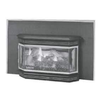
CONGRATULATIONS!
You are now the proud
owner of one of the finest
gas inserts on the market -
the QUADRA-FIRE
GB40I
INSTALLATION
FOR YOUR SAFETY:
• Extinguish any open flame.
• Open windows.
• Do not try to light any appliance.
• Do not touch any electric switch.
• Do not use any telephone in your building.
Improper installation, adjustment, alteration, service or maintenance can cause injury or
property damage. Refer to this manual for correct installation and operational procedures. for
assistance or additional information consult a qualified installer, service agency, or the gas
401 N. Wynne Street
Colville, WA 99114
North America's Best
GRAND BAY 40 GAS INSERT
This Manual contains instructions for
OPERATION, VENTING AND MAINTENANCE
,
If the information in this manual is not followed exactly, a
fire or explosion may result causing property damage,
personal injury, or death.
DO NOT store or use gasolive or other flammable vapors and
liquids in the vicinity of this or any other appliance.
WHAT TO DO IF YOU SMELL GAS
SAVE THESE INSTRUCTIONS
(Revised March 2000) Part #250-2641 #842-1270
WARNING
• Immediately call your gas supplier from a
neighbor's phone.
• Follow the gas supplier's instructions.
• If you cannot reach your gas supplier,
call the fire department.
WARNING
supplier.
www.aladdinhearth.com
aladdin@aladdinhearth.com
Advertisement
Table of Contents

Related Manuals for Quadra-Fire GB40I


Summary of Contents for Quadra-Fire GB40I
- Page 1 North America’s Best GRAND BAY 40 GAS INSERT CONGRATULATIONS! You are now the proud owner of one of the finest gas inserts on the market - the QUADRA-FIRE GB40I This Manual contains instructions for INSTALLATION OPERATION, VENTING AND MAINTENANCE WARNING...
-
Page 2: Welcome
Ask your Quadra-Fire Dealer for information on these options. From design, to fabri- cation, to shipping: Our guarantee of quality is more than a word, it’s Quadra-Fire tradition, and we proudly back this tradition with a Lifetime Warranty. -
Page 3: Notes
GB 40 I - FIREPLACE INSERT NOTES GB40-I MODEL PURCHASED SERIAL NUMBER DATE PURCHASED DEALERSHIP WHERE PURCHASED: DEALER PHONE NUMBER ADDITIONAL INFORMATION : ________________________________________________________________ ________________________________________________________________ ________________________________________________________________ ________________________________________________________________ ________________________________________________________________ ________________________________________________________________ ________________________________________________________________ ________________________________________________________________ ATTACH YOUR SALES RECEIPT AND WARRANTY STUB HERE: March 2000 Page 3... -
Page 4: Table Of Contents
GB 40 I - FIREPLACE INSERT TABLE OF CONTENTS Welcome ..............................2 Notes ................................. 3 Safety Label .............................. 5 Safety Notices ............................6 Specifications ............................7 Gas Line Connection ..........................7 Pressure Testing ............................7 Safety Listings ............................7 Dimensions ..............................8 Minimum Fireplace Clearances ........................ -
Page 5: Safety Label
GB 40 I - FIREPLACE INSERT SAFETY LABEL (As found on chain in lower front grill.) MANUFACTURED BY: GB40 -I NG GB40-I LP GAS-FIRED VENTED ROOM HEATER SERIAL NO. 401 N. Wynne CAN 1-2.1-M86 / ANSI 21.11.1a-1993 Colville, WA 99114 Report #061-S-07-4 GB40-I (NG) GB40-I (NG) -
Page 6: Safety Notices
GB 40 I - FIREPLACE INSERT SAFETY NOTICES This appliance should only be installed by a qualified installer. It is approved for installation in a bedroom. Bedroom installation in Canada requires that the stove be connected to a thermostat. The appliance must be electrically grounded in accordance with local codes, or the latest edition of the National Electric Code. -
Page 7: Specifications
(as seen below). Turn clockwise for a higher flame and counterclockwise for a lower flame INPUT SIDE TEST VALVE OUTPUT SIDE TEST VALVE LISTINGS The Quadra-Fire GB40-I is listed to ANSI Z21.11.1 and CAN1-2.1 by OMNI-Test Laboratories, Inc. March 2000 Page 7... -
Page 8: Dimensions
GB 40 I - FIREPLACE INSERT DIMENSIONS 11 7/8” (302mm) 7 1/2” (190mm) 20 1/4” (514mm) 20” (507mm) 19 1/8” (485mm) 9” (229mm) 21” (533mm) 26 1/4” (668mm) 15 1/4” (387mm) 11 3/8” (289mm) 8/3/4” (223mm) 4” flue 5 3/8” (136mm) 29 7/8”... -
Page 9: Minimum Fireplace Clearances
GB 40 I - FIREPLACE INSERT MINIMUM FIREPLACE CLEARANCES The following diagrams show the minimum fireplace dimensions that are required for installation of the Quadra-Fire GB40-I gas fireplace insert. March 2000 Page 9... -
Page 10: Clearances To Combustibles
GB 40 I - FIREPLACE INSERT CLEARANCES TO COMBUSTIBLES Minimum clearances to combustible materials From HEATER TO: SIDEWALL 10” (255mm) From HEATER TO: MANTEL 12.5” (320mm) * From PANEL TOP TO: MANTEL LEG 1” (25mm) MANTEL WIDTH 1” (25mm) * NOTE: For every 1” (25mm) of MANTEL WIDTH, ADD 1” (25mm) to Clearance “C”. Example: Mantel Width is 6”... -
Page 11: High Altitude Operation
GB 40 I - FIREPLACE INSERT HIGH ALTITUDE OPERATION For installations in the United States and at altitudes above 2000 feet, the appliance input shall be adjusted in accordance with local codes or, in the absence of any, follow the current ANSI Z223.1, National Fuel Gas Code. -
Page 12: Panel/Trim Installation
GB 40 I - FIREPLACE INSERT PANEL/TRIM INSTALLATION NOTE: PANEL AND TRIM MUST BE INSTALLED BEFORE BRICK 1. Slide side panels in between panel clamp and back of insert, see Fig. A. Slide top panel over side panels and attach with screws provided. Tighten panel clamps by the bolts located in the firebox, see Fig. B. 2. -
Page 13: Brick Installation
GB 40 I - FIREPLACE INSERT BRICK INSTALLATION CAUTION: Brick is extremely fragile, handle with care. The brick in this unit is packed within the firebox to prevent breakage during shipping. To install the brick, follow the directions below: Place brick A on the lower bottom left side of the firebox at an angle, and tip the top edge up until it slides into the slots on the top of the firebox and behind the manifold block. -
Page 14: Log Set Installation
GB 40 I - FIREPLACE INSERT INSTALLING THE LOG SET CORRECT LOG PLACEMENT IS IMPORTANT TO PREVENT SOOTING! The vacuum-formed ceramic logs are extremely fragile. PLEASE HANDLE CAREFULLY. Small chips on the logs can be covered up using the touch-up paint supplied with the stove.This appli- ance has been supplied with external shutter adjustments. -
Page 15: Door Installation
GB 40 I - FIREPLACE INSERT DOOR OPERATION INSTRUCTIONS 1. Verify that the proper door hook (part number 450-7490) is installed on the door. See Fig. A. 2. Install the door to check the latchbox adjustment. When closing the door, look between the door and the face of the stove at the latching arm. -
Page 16: Thermostat Installation
GB 40 I - FIREPLACE INSERT THERMOSTAT INSTALLATION If desired, a thermostat may be installed to regulate the Quadra-Fire GB40-I. It is important to use a thermostat designed for millivolt operation. Do not connect this appliance to a thermostat serving any other appliance. -
Page 17: Blower Power Cord
GB 40 I - FIREPLACE INSERT BLOWER POWER CORD The blower cord can be routed from either side of the panel set to a three prong grounded outlet. To attach the power cord to the insert, locate the black and white wires at the rear of the insert. Attach them to the black and white wires on the power cord (black to black, white to white). -
Page 18: Gas Connections
GB 40 I - FIREPLACE INSERT INSTALLATION PROCEDURES The following procedures show some of the basic installation applications. Remember that every installa- tion is different, and the installer should adjust to insure that the appliance is installed properly in every application. -
Page 19: Vent Attachment To Flue Collar
GB 40 I - FIREPLACE INSERT VENT ATTACHMENT TO FLUE COLLAR The GB40-I is equipped with a detachable flue collar. The draft hood is stationary to the insert. This allows you to make the connection in a very confined area. It can be reattached from the front of the unit as shown below. -
Page 20: Flue Clamp Instructions
GB 40 I - FIREPLACE INSERT FLUE CLAMP INSTRUCTIONS 1. Before installing the insert, attach the spill tube extension. Pull tube towards front of stove then slightly to the right to unhook locking bracket (see Fig. 4). 2. Remove the flue collar assembly. 3. -
Page 21: Venting Requirements
GB 40 I - FIREPLACE INSERT VENT TERMINATIONS REQUIREMENTS This unit is equipped with a thermal damper, which has been set at the factory. Do not remove or attempt to adjust. The vent termination must be located where it cannot become restricted or blocked by foreign material (for example, snow and leaves). -
Page 22: Terminations
GB 40 I - FIREPLACE INSERT TERMINATIONS WITH HORIZONTAL SECTIONS NOTE: Insert MUST be installed into an existing masonry fireplace or a zero clearance fireplace kit (see page 29 for part number). The horizontal section must not exceed 50% of the vertical rise. Provide a ¼” rise for each 12” horizontal run. -
Page 23: Exhaust Spillage And Testing Procedure
GB 40 I - FIREPLACE INSERT EXHAUST SPILLAGE AND TESTING PROCEDURE There is a spill switch located on the back of the insert below the draft hood, which is designed to shut down the insert due to a blocked flue or a severe down draft. The switch acts as a safety shutoff to prevent carbon monoxide or unburned gas from leaking into the room. -
Page 24: Lighting Instructions
GB 40 I - FIREPLACE INSERT LIGHTING INSTRUCTIONS FOR YOUR SAFETY READ BEFORE LIGHTING This appliance has a pilot that must be lit by hand using the piezo igniter. When lighting the pilot, follow these instructions exactly. BEFORE LIGHTING, smell all around the appliance area for gas. Be sure to smell next to the floor because some gas is heavier than air and will settle on the floor. -
Page 25: First Fire
GB 40 I - FIREPLACE INSERT FIRST FIRE NOTE: Never operate this appliance with the door open. NOTE: No electrical power supply is required for the gas control to operate. Standing pilot allows the valve to operate with manual switch or millivolt thermostat. WARNING: When the appliance is equipped with a 24 karat gold-plated door, you must clean all the fingerprints and oils from the gold surface before firing the appliance for the first... -
Page 26: Maintenance
GB 40 I - FIREPLACE INSERT MAINTENANCE CLEANING AND INSPECTION At least once yearly, preferably before the heating season, have the insert and venting system cleaned and inspected by a qualified service person. This will insure proper and safe operation throughout the year. -
Page 27: Glass Replacement
GB 40 I - FIREPLACE INSERT MAINTENANCE (cont.) GLASS REPLACEMENT (posted doors only; full view doors must be returned to the manufac- turer for glass replacement) WARNING: USE ONLY MANUFACTURER-SUPPLIED REPLACEMENT PARTS (PART NUMBER 842-1360 SIDE GLASS; 842-1280 CENTER GLASS). Use the supplied Allen wrench to open front. -
Page 28: Schematics
GB 40 I - FIREPLACE INSERT SCHEMATICS March 2000 Page 28... -
Page 29: Blower & Snap Disc Replacement
GB 40 I - FIREPLACE INSERT BLOWER AND SNAP DISC REPLACEMENT NOTE: BLOWER DOES NOT REQUIRE LUBRICATION. HOWEVER, WE RECOMMEND VACUUMING OR BRUSHING OFF DUST OR LINT FROM THE BLOWER BLADES AS NEEDED. BLOWER AND SNAP DISC REMOVAL This appliance is equipped with a 170 cfm convection blower that is automatically controlled by a tempera- ture-sensing snap disc (145º). -
Page 30: Conversion To Alternate Fuel
GB 40 I - FIREPLACE INSERT CONVERSION TO LIQUID PROPANE FUEL NOTE: THIS STOVE SHOULD ONLY BE CONVERTED BY AN AUTHORIZED SERVICE TECHNICIAN. Kit #842-4160 Tools Required: Kit Contents: 5/32" Allen wrench (1) #35 Pilot Orifice (3) Burner Orifices (sizes specified below) 3/8"... - Page 31 GB 40 I - FIREPLACE INSERT CONVERSION INSTRUCTIONS, CONT. 4. Replace Burner Orifices: Use a 3/8" socket wrench to remove existing burner orifices. See Fig. 3 Install new burner orifices as follows: Rear Burner = #53 Middle Burner = #63 Front Burner = #66 NOTE! Ensure that orifice size for each FIG.
-
Page 32: Troubleshooting
Check the wiring between the piezo and the igniter. If bad, fix wiring; if good, you may have a faulty piezo or cracked ceramic on the electrode. Call your Quadra-Fire dealer. If there is a spark: Try to light the insert with a match. The flame should either light or flutter. -
Page 33: Zero Clearance Fireplace Kit
For those installations in which it is difficult or impossible to connect the venting system to the insert with B-vent directly, there is an offset adapter available to facilitate this connection. The adapter adjusts from 0” to 3½” to help make the necessary connections. This part can be obtained from an authorized Quadra-Fire dealer March 2000 Page 33... -
Page 34: Accessories & Serviceparts
GB 40 I - FIREPLACE INSERT ACCESSORIES These may be ordered through your Quadra-Fire dealer. 841-0071 Panel and trim, standard (42½” x 28¼”) 841-0261 Panel and trim, medium (31½” x 44”) 841-0081 Panel and trim, oversized (51” x 34”) 841-0130 Panel and trim with access door, standard (42½”... -
Page 35: Warranty
Aladdin Hearth Products. This new Quadra-Fire product must be installed by a competent, authorized service contractor. It must be installed and operated at all times in accordance with the Installation, Operation and Maintenance Instructions included in this manual, as well as any applicable local and national codes. - Page 36 Grand Bay 40 Gas Insert OWNER’S MANUAL #250-2641/842-1270...