Table of Contents
Advertisement
Quick Links
Advertisement
Table of Contents

Related Manuals for Asus TS500-E8-PS4


Summary of Contents for Asus TS500-E8-PS4
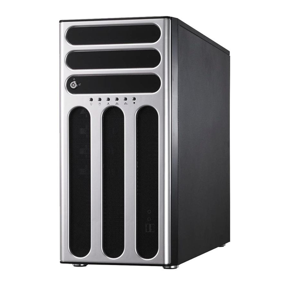
- Page 1 TS500-E8-PS4 Pedestal/5U Rackmount Server User Guide...
- Page 2 ASUSTeK COMPUTER INC. (“ASUS”). ASUS provides this manual “as is” without warranty of any kind, either express or implied, including but not limited to the implied warranties or conditions of merchantability or fitness for a particular purpose. In no...
-
Page 3: Table Of Contents
Contents Notices ........................vii REACH ......................vii Safety information ....................viii Australia statement notice ................ix About this guide ......................x Chapter 1: Product Introduction System package contents ................. 1-2 Serial number label ..................1-3 System specifications ................1-4 Front panel features ................... 1-6 Rear panel features .................. - Page 4 Internal connectors ..................4-9 Onboard LEDs ..................4-18 Chapter 5: BIOS setup Managing and updating your BIOS ............5-2 5.1.1 ASUS CrashFree BIOS 3 utility........... 5-2 5.1.2 ASUS EZ Flash Utility ..............5-3 5.1.3 BUPDATER utility ............... 5-4 BIOS setup program .................. 5-6 5.2.1...
- Page 5 Contents 5.4.4 Intel LAN I210 IO Configuration ..........5-13 5.4.5 Serial Port Console Redirection ..........5-14 5.4.6 APM ..................5-17 5.4.7 PCI Subsystem Settings ............5-18 5.4.8 Network Stack Configuration............. 5-19 5.4.9 CSM Configuration ..............5-20 5.4.10 Trusted Computing..............5-21 5.4.11 USB Configuration ..............
- Page 6 Running the Support DVD ..............7-13 ® Intel chipset device software installation ..........7-17 ® Installing the Intel I210 Gigabit Adapters driver ........7-19 VGA driver installation ................7-22 ® Intel Rapid Storage Technology enterprise 4.0 installation ....7-24 Appendices ASUS contact information ..................A-2...
-
Page 7: Notices
Radio Interference Regulations of the Canadian Department of Communications. This Class A digital apparatus complies with Canadian ICES-003. REACH Complying with the REACH (Registration, Evaluation, Authorization, and Restriction of Chemicals) regulatory framework, we publish the chemical substances in our products at ASUS REACH website at http://csr.asus.com/english/REACH.htm. -
Page 8: Safety Information
Safety information Electrical Safety • Before installing or removing signal cables, ensure that the power cables for the system unit and all attached devices are unplugged. • To prevent electrical shock hazard, disconnect the power cable from the electrical outlet before relocating the system. -
Page 9: Australia Statement Notice
If you require assistance please call ASUS Customer Service 1300 2787 88 or visit us at http://support.asus.com... -
Page 10: About This Guide
About this guide Audience This user guide is intended for system integrators, and experienced users with at least basic knowledge of configuring a server. Contents This guide contains the following parts: Chapter 1: Product introduction This chapter describes the general features of the server, including sections on front panel and rear panel specifications. - Page 11 Refer to the following sources for additional information, and for product and software updates. ASUS Server Web-based Management (ASWM) user guide This manual tells how to set up and use the proprietary ASUS server management utility. ASUS websites The ASUS websites worldwide provide updated information for all ASUS hardware and...
-
Page 13: Chapter 1: Product Introduction
Chapter 1: Product Introduction Product introduction This chapter describes the motherboard features and the new technologies it supports. -
Page 14: System Package Contents
1 x Front I/O Board • 1 x Front (80mm x 38mm) system fans • 1 x Rear (120mm x 38mm) system fan 1 x TS500-E8-PS4 Support CD (including ASWM*) 1 x Bag of screws Accessories 1 x ASMB8 Series DVD... -
Page 15: Serial Number Label
Serial number label Before requesting support from the ASUS Technical Support team, you must take note of the product’s serial number containing 14 characters such as xxS0xxxxxxxxxx shown as the figure below. With the correct serial number of the product, ASUS Technical Support team members can then offer a quicker and satisfying solution to your problems. -
Page 16: System Specifications
System specifications The ASUS TS500-E8-PS4 is a 5U barebone server system featuring the ® ® ASUS Z10PA-D8 Server Board. The server supports Intel LGA2011-3 Intel ® Xeon E5-2600 Processor v3 plus other latest technologies through the chipsets onboard. TS500-E8-PS4 Model Name... - Page 17 Enterprise Linux ® SuSE Linux Enterprise Server OS Support CentOS Ubuntu VMware Citrix XenServer Please find the latest OS support from http://www.asus.com/ (Subject to change without any notice) ASWM Enterprise Software Management Out of Band Solution Remote ASMB8-iKVM for KVM-over-Internet...
-
Page 18: Front Panel Features
Front panel features Message LED LAN1 LED LAN2 LED HDD access LED Locate LED Power LED (Reserved) Optical drive (optional) Empty 5.25-inch bays Security lock Power button Reset button 4-bay HDD cage Headset port* 4-bay HDD cage (Optional Set) Mic In port* USB 2.0 ports USB 3.0 ports Refer to section 1.7.1 Front panel LEDs for the LED descriptions. -
Page 19: Rear Panel Features
Power connector PS/2 mouse/keyboard port Chassis lock USB 2.0 ports VGA port 120mm x 38mm system fan Gigabit LAN ports USB 3.0 ports LAN port* Chassis intrusion switch Expansion slots *This port is for the ASUS ASMB8-iKVM controller only. ASUS TS500-E8-PS4... -
Page 20: Internal Features
Internal features The barebone server includes the basic components as shown. 500W Power Supply 120mm x 38mm system fan ASUS Z10PA-D8 Server Board Chassis intrusion switch Expansion card locks Optical drive (optional) 2 x 5.25-inch drive bays 4-bay HDD module (first set) SATA/SAS backplane board (first set, hidden) 10. -
Page 21: Led Information
HDD failure Green/Red Blinking HDD rebuilding using the RAID card LAN LEDs Blinking LAN accessing Locate LED Locates a specific server The Power, HDD Access, LAN and Message LEDs are visible even if the system front bezel is closed. ASUS TS500-E8-PS4... -
Page 22: Rear Panel Leds
1.7.2 Rear panel LEDs ACT/LINK LED ACT/LINK LED SPEED LED SPEED LED ACT/LINK LED SPEED LED ACT/LINK LED SPEED LED Status Description Status Description No link 10 Mbps connection GREEN Linked ORANGE 100 Mbps connection BLINKING Data activity GREEN 1 Gbps connection 1-10 Chapter 1: Product introduction... -
Page 23: Chapter 2: Hardware Information
Chapter 2: Hardware Information Hardware Information This chapter lists the hardware setup procedures that you have to perform when installing or removing system components. -
Page 24: Chassis Cover
Chassis cover 2.1.1 Removing the side cover • Ensure that you unplug the power cord before removing the side cover. • Take extra care when removing the side cover. Keep your fingers from components inside the chassis that can cause injury, such as the CPU fan, rear fan, and other sharp-edged parts. Remove the two screws that secure the side cover. Slide the side cover for about half an inch toward the rear until it is disengaged from the chasssis. -
Page 25: Reinstalling The Side Cover
Match and insert the lower sliding edge of the side cover to the corresponding chassis edge. Slide the side cover toward the front panel until it snaps in place. Drive in the two screws you removed earlier to secure the side cover. ASUS TS500-E8-PS4... -
Page 26: Central Processing Unit (Cpu)
Central Processing Unit (CPU) The motherboard comes with a surface mount LGA 2011-3 Socket designed for the Intel® Xeon E5-2600 v3 processor family. • Upon purchase of the motherboard, ensure that the PnP cap is on the socket and the socket contacts are not bent. Contact your retailer immediately if the PnP cap is missing, or if you see any damage to the PnP cap/socket contacts/motherboard components. ASUS will shoulder the cost of repair only if the damage is shipment/ transit-related. • Keep the cap after installing the motherboard. ASUS will process Return Merchandise Authorization (RMA) requests only if the motherboard comes with the cap on the LGA 2011-3 socket. • The product warranty does not cover damage to the socket contacts resulting from incorrect CPU installation/removal, or misplacement/loss/incorrect removal of the PnP cap. 2.2.1 Installing the CPU To install a CPU: Locate the CPU socket on the motherboard. Before installing the CPU, ensure that the socket box is facing toward you and the triangle mark is on the top-right position. Triangle mark... - Page 27 Press the left load lever down with your thumb (A), move it to the right until it is released from the retention tab (B) then gently lift the load lever (C). To prevent damage to the socket pins, do not remove the PnP cap unless you are installing a CPU. Load lever Press the right load lever with your thumb (D), move it to the left until it is released from then gently lift the load lever (F). ASUS TS500-E8-PS4...
- Page 28 Push the left load lever to slightly lift the load plate (G). edge of the Load plate Do not insert the load lever into the retention tab. Hold the edge then gently lift the load plate (H). Load plate Get the CPU. Triangle mark 7. Align and position the CPU over the socket ensuring that the triangle mark on the CPU matches the triangle mark on the socket box. Install the CPU into the slot. The CPU fits in only one correct orientation. DO NOT force the CPU into the socket to prevent bending the CPU pins on the socket.
- Page 29 10. Push down the right load lever (I) ensuring that the edge of the load plate is fixed and tucked securely under the lever (J) then insert the right load lever under the retention tab (K). The PnP cap pops out of the load plate when the right load lever is inserted into the retention tab. Keep the PnP cap. ASUS will process Return Merchandise Authorization (RMA) requests only if the motherboard comes with the PnP cap on the LGA 2011-3 socket. PnP cap 11. Push down the left load lever (L) then Retention tab insert it under the retention tab (M). ASUS TS500-E8-PS4...
- Page 30 12. Apply some Thermal Interface Material to the exposed area of the CPU that the heatsink will be in contact with. • Ensure that the Thermal Interface Material is spread in an even thin layer. • Some heatsinks come with pre-applied Thermal Interface Material. If so, skip this step. The Thermal Interface Material is toxic and inedible. DO NOT eat it. If it gets into your eyes or touches your skin, wash it off immediately, and seek professional medical help. 13. Connect the CPU fan cable to the connector on the motherboard labeled CPU_FAN1 / CPU_FAN2. DO NOT forget to connect the CPU fan connector! Hardware monitoring errors can occur if you fail to plug this connector. Chapter 2: Hardware setup...
-
Page 31: Installing The Cpu Heatsink
2.2.2 Installing the CPU heatsink To install the CPU heatsink: Loose the rear fan retainers with both hands to remove the fan and unplug the rear fan connector. Connect the CPU heatsink fan connector to CPU_FAN2 connector. Connect the rear fan connector to REAR_FAN1 connector. Align and click the rear fan into place. ASUS TS500-E8-PS4... - Page 32 Place the CPU heatsink and fan on top of the installed CPU, ensuring that the four screws match the holes on the support plate, and the arrow on the fan faces the rear panel of the server chassis. Twist each of the four screws with a Philips (cross) screwdriver just enough to attach the CPU heatsink and fan to the motherboard. When the four screws are attached, tighten them one by one to completely secure the CPU heatsink and fan. Tighten the four heatsink screws in a diagonal sequence. Do not forget to connect the CPU heatsink and fan connector. Hardware monitoring errors can occur if you fail to plug this connector. 2-10 Chapter 2: Hardware setup...
-
Page 33: System Memory
System memory 2.3.1 Overview The motherboard comes with eight (8) Double Data Rate 4 (DDR4) Dual Inline Memory Modules (DIMM) sockets. The figure illustrates the location of the DDR4 DIMM sockets: ASUS TS500-E8-PS4 2-11... -
Page 34: Memory Configurations
2.3.2 Memory Configurations You may install 4 GB, 8 GB, 16 GB, and 32 GB RDIMMs or 32 GB and 64 GB LR-DIMMs into the DIMM sockets using the memory configurations in this section. • Refer to ASUS Server AVL for the updated list of compatible DIMMs. • When installing DIMMs, always start from slot A1 (CPU1) and E1 (CPU2). • Always install DIMMs with the same CAS latency. For optimum compatibility, it is recommended that you obtain memory modules from the same vendor. Single CPU configuration You can refer to the following recommended memory population for a single CPU configuration. Single CPU configuration (must be installed on CPU1) DIMM 1 DIMM... -
Page 35: Installing A Dimm On A Single Clip Dimm Socket
Unlocked retaining clip A DIMM is keyed with a notch so that it fits in only one direction. DO NOT force a DIMM into a socket in the wrong direction to avoid damaging the DIMM. Hold the DIMM at both ends then insert the DIMM into the socket. Apply force to both ends of the DIMM simultaneously until the retaining clip clicks into place and the DIMM is seated securely in place. Locked Retaining Clip Always insert the DIMM into the socket VERTICALLY to prevent DIMM notch damage. • To install two or more DIMMs, refer to the user guide bundled with the motherboard package. • Refer to the user guide for qualified vendor lists of the memory modules. Removing a DIMM from a single clip DIMM socket Press the retaining clip outward to unlock the DIMM. Remove the DIMM from the socket. Support the DIMM lightly with your fingers when pressing the retaining clips. The DIMM might get damaged when it flips out with extra force. ASUS TS500-E8-PS4 2-13... -
Page 36: Front Panel Assembly
Front panel assembly Before you can install a 5.25-inch drive, you should first remove the front panel assembly (front bezel and front panel cover). 2.4.1 Removing the front panel assembly To remove the front panel assembly Locate the three hooked tabs on the chassis side rail. Shift the hooked tabs and take off the front bezel. 2.4.2 Reinstalling the front panel assembly To reinstall the front panel assembly: Hook the other side of the front panel assembly to the chassis. Swing the front panel assembly and snap it back into place. 2-14 Chapter 2: Hardware setup... -
Page 37: Inch Drives
You must remove the front panel assembly before installing a 5.25-inch drive. Installing a 5.25-inch drive Unscrew and remove the metal cover of the bay where you want to install the 5.25-inch drive, and take off the plastic cover on the front bezel at the same position. Insert the drive into the bay and slide the bay lock to the right until it clicks in place. Connect the SATA cable to the SATA connector on the back of the drive. Connect a power plug from the power supply to the power connector on the back of the drive. ASUS TS500-E8-PS4 2-15... -
Page 38: Sata/Sas Hard Disk Drives
SATA/SAS hard disk drives The hard disk drive module cage on the front panel, including externally removable trays for mounting either SATA or SAS hard disk drives, allows you to access the drive trays by simply opening the front bezel. An HDD module cage comes with a SATA or SAS backplane. Take note of the type of HDD module cage you purchase before buying hard disks. 2.6.1 Installing the HDD module cage Examine the chassis and ensure the bay space is free of wires and other obstructions. Level the HDD module cage latch counterclockwise. Insert the HDD module cage into the bay. When the HDD module cage is completely inserted, the cage latch will be pushed back clockwise. Lock the cage latch properly. Connect the appropriate cables to the SATA/SAS backplane on the HDD module cage. 2-16 Chapter 2: Hardware setup... -
Page 39: Removing The Hdd Module Cage
2.6.2 Removing the HDD module cage Disconnect all the cables from the SATA/SAS backplane on the HDD module cage. Level the HDD module cage latch counterclockwise. The HDD module cage will be pushed out of the chassis. Completely pull out the HDD module cage. ASUS TS500-E8-PS4 2-17... -
Page 40: Installing A Hot-Swap Sata/Sas Hard Disk Drive
2.6.3 Installing a hot-swap SATA/SAS hard disk drive Release a drive tray by pushing the spring lock to the right, and then pulling the tray lever outward. The drive tray ejects slightly after you pull out the lever. Firmly hold the tray lever and pull the drive tray out of the bay. Take note of the drive tray holes. Each side has three holes to fit different types of hard disk drives. Use two screws on each side to secure the hard disk drive. 2-18 Chapter 2: Hardware setup... - Page 41 Carefully insert the drive tray and push it all the way to the depth of the bay until just a small fraction of the tray edge protrudes. When installed, the SATA/SAS connector on the drive connects to the SATA/SAS interface on the backplane. Push the tray lever until it clicks, and secures the drive tray in place. The drive tray is correctly placed when its front edge aligns with the bay edge. Repeat steps 1 to 6 if you wish to install a second SATA/SAS drive. ASUS TS500-E8-PS4 2-19...
-
Page 42: Removing And Reinstalling The Backplane
2.6.4 Removing and reinstalling the backplane DO NOT remove the backplane unless necessary! Remove all hot-swap HDD trays from the chassis. Disconnect all cables from the SATA/ SAS backplane. Loosen the four screws on the backplane. Firmly hold the backplane, lift it up and remove it from the module. Follow the previous instructions in reverse to reinstall the backplane 2-20 Chapter 2: Hardware setup... -
Page 43: Expansion Cards
Expansion cards The system is designed with an expansion card lock on the rear panel for you to install or remove an expansion card in less steps. Ensure to unplug the power cord before installing or removing expansion cards. Failure to do so may cause severe damage to the motherboard and other system components! 2.7.1 Installing an expansion card Before installing the expansion card, read the documentation that came with it and make the necessary hardware settings for the card. Lay the system on its side on a flat, stable surface. Push down the expansion card lock latch (step a) and lift up the expansion card lock (step b), as shown in the right figure. Remove the metal slot cover opposite the slot where you wish to install an expansion card. ASUS TS500-E8-PS4 2-21... - Page 44 Align the card’s golden fingers with the slot, and then press firmly until the card is completely seated on the slot. Push the expansion card lock back to its original position. A light click indicates that the card is locked in place. When installing a graphics card on a PCIex16 slot, the PCIe slot right beside it does not function. 2-22 Chapter 2: Hardware setup...
-
Page 45: Cable Connections
Cable connections The bundled system cables are pre-connected before shipment. You do not need to disconnect these cables unless you will remove pre-installed components to install additional devices. Refer to Chapter 4 for detailed information on the connectors. 2.8.1 Motherboard connections ASUS TS500-E8-PS4 2-23... - Page 46 Standard cables connected to the motherboard 24-pin ATX power connector (from power supply to motherboard) 8-pin 12V power connector (from power supply to motherboard) System fan connector (from system fan to motherboard) USB connector (from motherboard to front I/O board) SATA ports (miniSAS connector support) connectors (system default; from motherboard to SATA/SAS backplane) System auxiliary panel connector (from motherboard to front I/O board) System panel connector (from motherboard to front I/O board) 2-24 Chapter 2: Hardware setup...
-
Page 47: Sata/Sas Backplane Connections
Front side The front side of the SATA/SAS backplane faces the front panel when installed. This side includes four SATA/SAS connectors for the hot swap drive trays. HDD1 HDD2 Drive status LEDs HDD3 HDD4 Each SATA/SAS connector is labeled (HDD1, HDD2, HDD3, HDD4) so you can easily determine their counterpart connectors at the back side of the backplane. Refer to the table for reference. HDD Device Front side connector Back side connector HDD 1 HDD1 CON1 HDD 2 HDD2 CON2 HDD 3 HDD3 CON3 HDD 4 HDD4 CON4 ASUS TS500-E8-PS4 2-25... -
Page 48: Back Side
Back side The back side of the SATA/SAS backplane faces the rear panel when installed. This side includes the power connectors and SATA/SAS interfaces for the motherboard Serial ATA connectors or the SAS card. CON1 CON2 SGPIO_SEL1 SGPIO2 CON4 SGPIO3 CON3 SGPIO1 BPSMB1 Connectors Description SGPIO1 Connects to SATA SGPIO1 connector on the motherboard Connects to SAS PSGPIO1 connector on the motherboard SGPIO2 SGPIO3 Connects to SAS PSGPIO2 connector on the motherboard BPSMB1 Connects to Front panel SMB connector on the motherboard Connects to 4-pin plug of the power supply CON1/CON2/ Connects to SATA/SAS connectors on the motherboard CON3/CON4 Move the SGPIO_SEL1 jumper on the SATA/SAS backplane to 2–3 when installing the PIKE RAID card. 2-26 Chapter 2: Hardware setup... -
Page 49: Removable Components
Removing the front system fan To remove the front system fan: Remove the two screws that secure the right side cover. Locate the front system fan near the 5.25-inch drive bays. Squeeze the front system fan latches (step a) and pull out the front system fan (step b), as shown in the right figure. Follow the previous instructions in reverse to reinstall the front system fan. ASUS TS500-E8-PS4 2-27... - Page 50 Removing the rear system fan To remove the rear system fan: Unplug the system fan cable from the REAR_FAN1 connector on the motherboard. Shift the two hooked tabs leftward and rightward respectively, then carefully remove the system fan. Follow the previous instructions in reverse to reinstall the rear system fan. 2-28 Chapter 2: Hardware setup...
-
Page 51: Chassis Footpads
2.9.2 Chassis footpads The barebone server system is shipped with four footpads attached to the bottom of the chassis for stability. You need to remove these footpads if you wish to install the system to a rack (Refer to Chapter 3: Installation options of this user guide, and to the “Rackmount Kit” user guide for instructions) To remove the footpads: Lay the system chassis on its side. Remove the footpad by rotating it counterclockwise with a Philips (cross) screwdriver. Repeat step 1 and 2 to remove the other three footpads. ASUS TS500-E8-PS4 2-29... - Page 52 2-30 Chapter 2: Hardware setup...
-
Page 53: Chapter 3: Installation Options
Chapter 3: Installation Options Installation Options This chapter describes how to install the optional components and devices into the barebone server. -
Page 54: Preparing The System For Rack Mounting
Preparing the system for rack mounting • The items required for the optional configurations described in this chapter are not included in the standard barebone system package. These items are purchased separately. • We recommend that you allot at least 1U space above the server system to ensure optimal thermal performance. Removing the footpads Refer to section 2.9.2 Chassis footpads for instructions on removing the footpads. Removing the top cover Unscrew and slide the top cover toward the rear panel, and then lift it up from the chassis. Chapter 3: Installation options... -
Page 55: Attaching The Inner Rail To The Server
Attaching the inner rail to the server Slide out the inner rail from the rackmount rail kit. Align the screw holes on the inner rail and the chassis top, and then secure the inner rail to the chassis top with screws. Repeat the previous steps to secure the other inner rail to the bottom of the chassis with screws. Attaching the rails to the rack To attach the rails to the rack: Select one unit of space (1U) on the rack where you wish to install the server. 1U space Loosen the two screws on the rack rails. ASUS TS500-E8-PS4... -
Page 56: Mounting The Server To The Rack
Align the front end holes of a rack rail pair to the 1U space. Drive in two screws on the outer holes to secure the front end. Find the rear 1U space that corresponds to the front 1U space where you attached the rail. Drive in two screws on the outer holes to secure the rear end. From the rack front, find the corresponding 1U space for the second rail pair. Repeat steps 3–6 to attach the second rail pair. Mounting the server to the rack To mount the server to the rack: Align the server rails with the rack rails. Push the server all the way into the rack. Chapter 3: Installation options... -
Page 57: Chapter 4: Motherboard Information
Chapter 4: Motherboard Information Motherboard Information This chapter includes the motherboard layout and brief descriptions of the jumpers and internal connectors. -
Page 58: Motherboard Layout
Motherboard layout Z10PA-D8 Chapter 4: Motherboard information... - Page 59 Z10PA-D8C ASUS TS500-E8-PS4...
- Page 60 Layout contents Slots/Sockets Page 1. CPU sockets 2. DDR4 sockets 3. PCI Express x16 / PCI Express x8 4-17 Jumpers Page 1. Clear RTC RAM (CLRTC1) 2. VGA controller setting (3-pin VGA_SW1) 3. LAN controller setting (3-pin LAN_SW1, LAN_SW2) 4. ME firmware force recovery setting (3-pin ME_RCVR1) 5. DDR4 thermal event setting (3-pin DIMMTRIP1) 6. RAID configuration utility selection (3-pin RAID_SEL1) 7. PMBus 1.2 PSU select jumper (3-pin SMART_PSU1) Internal connectors Page 1.
-
Page 61: Jumpers
CMOS memory of date, time, and system setup parameters by erasing the CMOS RTC RAM data. The onboard button cell battery powers the RAM data in CMOS which include system setup information such as system passwords. To erase the RTC RAM: Turn OFF the computer and unplug the power cord. Move the jumper cap from the default pins 1–2 to pins 2–3. Keep the cap on pins 2–3 for about 5 to 10 seconds, then move the cap back to pins 1–2. Plug the power cord and turn ON the computer. Hold down the <Del> key during the boot process and enter BIOS setup to re- enter data. DO NOT remove the cap on CLRTC jumper default position except when clearing the RTC RAM. Removing the cap will cause system boot failure! If the steps above do not help, remove the onboard battery and move the jumper again to clear the CMOS RTC RAM data. After the CMOS clearance, reinstall the battery. ASUS TS500-E8-PS4... - Page 62 VGA controller setting (3-pin VGA_SW1) This jumper allows you to enable or disable the onboard VGA controller. Set to pins 1–2 to activate the VGA feature. LAN controller setting (3-pin LAN_SW1, LAN_SW2) These jumpers allow you to enable or disable the onboard LAN_SW1 or LAN_SW2. Set to pins 1–2 to activate the Gigabit LAN feature. Chapter 4: Motherboard information...
- Page 63 ME firmware force recovery setting (3-pin ME_RCVR1) ® This jumper allows you to force Intel Management Engine (ME) boot from recovery mode when ME becomes corrupted. DDR4 thermal event setting (3-pin DIMMTRIP1) This jumper allows you to enable or disable DDR4 DIMM thermal sensing event pin. ASUS TS500-E8-PS4...
- Page 64 RAID configuration utility selection (3-pin RAID_SEL1) This jumper allows you to select the RAID configuration utility to use when you create disk arrays. Place the jumper caps over pins 1–2 to use the third party software LSI MegaRAID software RAID Configuration Utility; otherwise, place the jumper caps to ® pins 2–3 to use the Intel Rapid Storage Technology enterprise SATA Option ROM Utility. The RAID configuration utility selection is available to Z10PA-D8 SKU only. PMBus 1.2 PSU select jumper (3-pin SMART_PSU1) This jumper allows you to select PSU PMBus version. Set to pins 1–2 for PMBus, set to pins 2–3 for others. Chapter 4: Motherboard information...
-
Page 65: Internal Connectors
Serial ATA 6.0 Gbps connectors (7-pin SATA1, SATA2, SATA3, SATA4, SATA5, SATA6 [Light Blue]) (7-pin SSATA1, SSATA2, SSATA3 [Gray], SSATA4 [Light Gray]) ® Supported by the Intel 612 Series chipset, this connector is for the Serial ATA signal cables for Serial ATA hard disk drives that allows up to 6 Gbps of data transfer rate. If you installed Serial ATA hard disk drives, you can create a RAID 0, RAID 1, RAID 10, or RAID 5 configuration. • The actual data transfer rate depends on the speed of Serial ATA hard disks installed. • The SSATA4 [Light Gray] will be automatically turned off if the M.2 connector (NGFF) is occupied. ASUS TS500-E8-PS4... - Page 66 M.2 (NGFF) connector (NGFF1) This connector allows you to install an M.2 device. This connector supports type 2242 devices on both PCI-E and SATA interface. The M.2 (NGFF) device is purchased separately Power Supply SMBus connector (5-pin PSUSMB1) This connector allows you to connect SMBus (System Management Bus) to the PSU (power supply unit) to read PSU information. Devices communicate with an SMBus host and/or other SMBus devices using the SMBus interface. Power supply is required to meet PMBus specification and customized BMC FW may be needed. Please contact ASUS if your need further support. This connector functions only when you install the ASUS ASMB8. Chapter 4: Motherboard information 4-10...
- Page 67 USB 2.0 connector (10-1 pin USB34) These connectors are for USB 2.0 ports. Connect the USB module cables to connectors USB56. These USB connectors comply with USB 2.0 specification that supports up to 480 Mb/s connection speed. USB 3.0 connector (20-1 pin USB3_34) This connector allows you to connect a USB 3.0 module for additional USB 3.0 front or rear panel ports. With an installed USB 3.0 module, you can enjoy all the benefits of USB 3.0 including faster data transfer speeds of up to 5Gbps, faster charging time for USB-chargeable devices, optimized power efficiency, and backward compatibility with USB 2.0. ASUS TS500-E8-PS4 4-11...
- Page 68 FRNT_FAN2, FRNT_FAN3, FRNT_FAN4, FRNT_FAN5, REAR_FAN1, REAR_FAN2) The fan connectors support cooling fans. Connect the fan cables to the fan connectors on the motherboard, ensuring that the black wire of each cable matches the ground pin of the connector. • DO NOT forget to connect the fan cables to the fan connectors. Insufficient air flow inside the system may damage the motherboard components. • These are not jumpers! DO NOT place jumper caps on the fan connectors! • All fans feature the ASUS Smart Fan technology. Chapter 4: Motherboard information 4-12...
- Page 69 Serial port connector (10-1 pin COM1) This connector is for the serial COM port. Connect the serial port module cable to one of these connectors, then install the module to a slot opening at the back of the system chassis. Trusted Platform Module connector (20-1 pin TPM1) This connector supports a Trusted Platform Module (TPM) system, which can securely store keys, digital certificates, passwords, and data. A TPM system also helps enhance network security, protects digital identities, and ensures platform integrity. ASUS TS500-E8-PS4 4-13...
- Page 70 EATX power connectors (24-pin EATXPWR1, 8-pin EATX12V1, 8-pin EATX12V2) These connectors are for the SSI or ATX power supply plugs. The power supply plugs are designed to fit these connectors in only one orientation. Find the proper orientation and push down firmly until the connectors completely fit. • DO NOT forget to connect the 24+8-pin power plugs when using 85W or below CPU; otherwise, the system will not boot up. • DO NOT forget to connect the 24+8+8-pin power plugs when using 105W or above CPU; otherwise, the system will not boot up. • Use of a PSU with a higher power output is recommended when configuring a system with more power-consuming devices. The system may become unstable or may not boot up if the power is inadequate. • Ensure that your power supply unit (PSU) can provide at least the minimum power required by your system. Minimum requirement of ATX power supply 1) 500W 2) All+12V output > 20A. Chapter 4: Motherboard information 4-14...
- Page 71 Hard disk drive activity LED (2-pin HDD LED) This 2-pin connector is for the HDD Activity LED. Connect the HDD Activity LED cable to this connector. The HD LED lights up or flashes when data is read from or written to the HDD. Power button/soft-off button (2-pin PWRSW) This connector is for the system power button. Pressing the power button turns the system on or puts the system in sleep or soft-off mode depending on the BIOS settings. Pressing the power switch for more than four seconds while the system is ON turns the system OFF. Reset button (2-pin RESET) This 2-pin connector is for the chassis-mounted reset button for system reboot without turning off the system power. ASUS TS500-E8-PS4 4-15...
- Page 72 Auxiliary panel connector (20-2 pin AUX_PANEL1) This connector is for additional front panel features including front panel SMB, locator LED and switch, and LAN LEDs. Front panel SMB (10-2 pin FPSMB) These connectors are for the front panel SMBus cable. LAN activity LED (2-pin LAN1_LINKACTLED, LAN2_LINKACTLED) These connectors are for Gigabit LAN activity LEDs on the front panel. Locator LED (2-pin LOCATORLED1, LOCATORLED2) These connectors are for the locator LED1 and LED2 on the front panel. Connect the Locator LED cables to these 2-pin connector. The LEDs will light up when the Locator button is pressed.
- Page 73 Hard disk activity LED connector (4-pin HDLED1) This LED connector is for the storage add-on card cable connected to the SATA or SAS add-on card. The read or write activities of any device connected to the SATA or SAS add-on card causes the front panel LED to light up. Chassis Intrusion (2-pin INTRUSION1) These leads are for the intrusion detection feature for chassis with intrusion sensor or microswitch. When you remove any chassis component, the sensor triggers and sends a high level signal to these leads to record a chassis intrusion event. The default setting is short CHASSIS# and GND pin by jumper cap to disable the function. ASUS TS500-E8-PS4 4-17...
-
Page 74: Onboard Leds
Standby Power LED (SB_PWR1) The motherboard comes with a standby power LED. The green LED lights up to indicate that the system is ON, in sleep mode, or in soft-off mode. This is a reminder that you should shut down the system and unplug the power cable before removing or plugging in any motherboard component. The illustration below shows the location of the onboard LED. Baseboard Management Controller LED (BMC_LED1) The green heartbeat LED blinks per second to indicate that the ASMB8 is working normally. • The heartbeat LED functions only when you install the ASUS ASMB8. • The Baseboard Management Controller is available to Z10PA-D8 SKU only. Chapter 4: Motherboard information 4-18... - Page 75 CPU Warning LED (ERR_CPU1, ERR_CPU2) The CPU warning LEDs light up to indicate failure on either CPU1, CPU2, or both. CATT LED (CATTERR_LED1) The CATT LED indicates that the system has experienced a fatal or catastrophic error and cannot continue to operate. ASUS TS500-E8-PS4 4-19...
- Page 76 Q-Code LEDs (LED1) The Q-Code LED provides a 2-digit display that shows the status of your system. Refer to the Q-Code table of this user guide for more information about the 2-digit codes. Chapter 4: Motherboard information 4-20...
- Page 77 MRC Progress Memory Init. MRC Progress Memory Init. MRC Progress Memory Init. MRC Progress Memory Init. MRC Progress Memory Init. MRC Progress Memory Init. MRC Progress Memory Init. MRC Progress Memory Init. MRC Progress Memory Init. MRC Progress Memory Init. MRC Progress Memory Init. Done MRC Progress Other config. After RC end Progress Memory already installed. Progress CPU Init. Progress CPU Init. Progress CPU Init. Progress DXE Initial Program Load(IPL) (continued on the next page) ASUS TS500-E8-PS4 4-21...
- Page 78 Q-Code table Action PHASE POST CODE TYPE DESCRIPTION Progress DXE Core Started Progress DXE NVRAM Init. Progress SB run-time init. Progress DXE CPU Init Progress NB Init. DXE(Driver Progress NB Init. Execution Progress NB Init. Environment) phase Progress SB Init. Progress SB Init. Progress SB Init. Progress ACPI Init. Progress CSM Init. Progress BDS started Progress Connect device event Progress PCI Bus Enumeration.
-
Page 79: Chapter 5: Bios Setup
Chapter 5: BIOS setup BIOS setup This chapter tells how to change the system settings through the BIOS Setup menus. Detailed descriptions of the BIOS parameters are also provided. -
Page 80: Managing And Updating Your Bios
BIOS in the future. Copy the original motherboard BIOS using the BUPDATER utility. 5.1.1 ASUS CrashFree BIOS 3 utility The ASUS CrashFree BIOS 3 is an auto recovery tool that allows you to restore the BIOS file when it fails or gets corrupted during the updating process. You can update a corrupted BIOS file using a USB flash drive that contains the updated BIOS file. -
Page 81: Asus Ez Flash Utility
5.1.2 ASUS EZ Flash Utility The ASUS EZ Flash Utility feature allows you to update the BIOS without having to use a DOS‑based utility. Before you start using this utility, download the latest BIOS from the ASUS website at www.asus.com. To update the BIOS using EZ Flash Utility: Insert the USB flash disk that contains the latest BIOS file into the USB port. Enter the BIOS setup program. Go to the Tool menu then select ASUS EZ Flash Utility. -
Page 82: Bupdater Utility
The BUPDATER utility allows you to update the BIOS file in the DOS environment using a bootable USB flash disk drive with the updated BIOS file. Updating the BIOS file To update the BIOS file using the BUPDATER utility: Visit the ASUS website at www.asus.com and download the latest BIOS file for the motherboard. Save the BIOS file to a bootable USB flash disk drive. Copy the BUPDATER utility (BUPDATER.exe) from the ASUS support website at support.asus.com to the bootable USB flash disk drive you created earlier. Boot the system in DOS mode, then at the prompt, type: BUPDATER /i[filename].CAP where [filename] is the latest or the original BIOS file on the bootable USB flash disk drive, then press <Enter>. A:\>BUPDATER /i[file name].CAP Chapter 5: BIOS setup... - Page 83 The utility verifies the file, then starts updating the BIOS file. ASUS Tek. EzFlash Utility Current Platform New Platform Platform : Z10PA-08 Platform : Z10PA-08 Version : 0301 Version : 0301 Build date: 05/13/2014 Build date: 05/13/2014 Start Programming Flash. DO NOT SHUTDOWN THE SYSTEM!!! Write DO NOT shut down or reset the system while updating the BIOS to prevent system boot failure! The utility returns to the DOS prompt after the BIOS update process is completed.
-
Page 84: Bios Setup Program
If the system becomes unstable after changing any BIOS settings, load the default settings to ensure system compatibility and stability. Press <F5> and select Yes to load the BIOS default settings. • The BIOS setup screens shown in this section are for reference purposes only, and may not exactly match what you see on your screen. • Visit the ASUS website (www.asus.com) to download the latest BIOS file for this motherboard. Chapter 5: BIOS setup... -
Page 85: Bios Menu Screen
For changing the Server Mgmt settings For changing the event log settings Event Logs Monitor F or displaying the system temperature, power status, and changing the fan settings Security For changing the security settings Boot For changing the system boot configuration Tool For configuring options for special functions Exit For selecting the exit options To select an item on the menu bar, press the right or left arrow key on the keyboard until the desired item is highlighted. ASUS TS500-E8-PS4... -
Page 86: Menu Items
5.2.3 Menu items The highlighted item on the menu bar displays the specific items for that menu. For example, selecting Main shows the Main menu items. The other items (Event Logs, Advanced, Monitor, Boot, Tool, and Exit) on the menu bar have their respective menu items. 5.2.4 Submenu items A solid triangle before each item on any menu screen means that the item has a submenu. To display the submenu, select the item then press <Enter>. 5.2.5 Navigation keys At the bottom right corner of a menu screen are the navigation keys for the BIOS setup program. Use the navigation keys to select items in the menu and change the settings. -
Page 87: Main Menu
Main menu When you enter the BIOS Setup program, the Main menu screen appears. The Main menu provides you an overview of the basic system information, and allows you to set the system date, time, language, and security settings. 5.3.1 System Date [Day xx/xx/xxxx] Allows you to set the system date. 5.3.2 System Time [xx:xx:xx] Allows you to set the system time. ASUS TS500-E8-PS4... -
Page 88: Advanced Menu
Advanced menu The Advanced menu items allow you to change the settings for the CPU and other system devices. Take caution when changing the settings of the Advanced menu items. Incorrect field values can cause the system to malfunction. Chapter 5: BIOS setup 5-10... -
Page 89: Acpi Settings
Allows you to enable or disable the ability of the system to hibernate (OS/Sleep State). Configuration options: [Disabled] [Enabled] This option may be not effective with some OS. 5.4.2 Smart Settings SMART Self Test [Disabled] Allows you to run SMART Self Test on all HDDs during POST. Configuration options: [Disabled] [Enabled] ASUS TS500-E8-PS4 5-11... -
Page 90: Nct6779D Super Io Configuration
5.4.3 NCT6779D Super IO Configuration Serial Port 1 / Serial Port 2 Configuration Allows you to set the parameters of Serial Port 1/ Serial Port 2. Serial Port [Enabled] Allows you to enable or disable Serial Port. Configuration options: [Disabled] [Enabled] Change Settings [Auto] Allows you to choose the setting for Super IO device. -
Page 91: Intel Lan I210 Io Configuration
Allows you to select the Intel LAN ROM type. Configuration options: [PXE] [iSCSI] Intel LAN I210 LAN1 / LAN2 Enable [Enabled] Allows you to enable or disable the Intel LAN. Configuration options: [Disabled] [Enabled] The following items appear only when Intel LAN I210 LAN1 / LAN2 Enable is set to [Enabled]. LAN1/ LAN2 Option ROM Support [Enabled] Allows you to load the Intel LAN ROM. Configuration options: [Disabled] [Enabled] ASUS TS500-E8-PS4 5-13... -
Page 92: Serial Port Console Redirection
5.4.5 Serial Port Console Redirection COM1/COM2 Console Redirection [Enabled] Allows you to enable or disable the console redirection feature. Configuration options: [Disabled] [Enabled] The following item appears only when you set Console Redirection to [Enabled]. Console Redirection Settings This item becomes configurable only when you enable the Console Redirection item. The settings specify how the host computer and the remote computer (which the user is using) will exchange data. - Page 93 VT -UTF8 Combo Key Support [Enabled] This allows you to enable the VT -UTF8 Combination Key Support for ANSI/VT100 terminals. Configuration options: [Disabled] [Enabled] Recorder Mode [Disabled] With this mode enabled only text will be sent. This is to capture Terminal data. Configuration options: [Disabled] [Enabled] Legacy OS Redirection Resolution [80x24] This allows you to set the number of rows and columns supported on the Legacy OS. Configuration options: [80x24] [80x25] Putty Keypad [VT100] This allows you to select the FunctionKey and Keypad on Putty. Configuration options: [VT100] [LINUX] [XTERMR6] [SCO] [ESCN] [VT400] ASUS TS500-E8-PS4 5-15...
-
Page 94: Console Redirection Settings
Redirection After BIOS POST [Bootloader] This setting allows you to specify if Bootloader is selected than Legacy console redirection. Configuration options: [Always Enable] [Bootloader] Serial Port for Out-of-Band Management/ Windows Emergency Management Services (EMS) Console Redirection [Disabled] Allows you to enable or disable the console redirection feature. Configuration options: [Disabled] [Enabled] The following item appears only when you set Console Redirection to [Enabled]. -
Page 95: Apm
Configuration options: [Power Off] [Power On] [Last State] Power On By PCIE [Disabled] [Disabled] Disables the PCIE devices to generate a wake event. [Enabled] Enables the PCIE devices to generate a wake event. Power On By Ring [Disabled] [Disabled] Disables the PCIE devices to generate a wake event. [Enabled] Enables the PCIE devices to generate a wake event. Power On By RTC [Disabled] [Disabled] Disables RTC to generate a wake event. [Enabled] When set to [Enabled], the items RTC Alarm Date (Days) and Hour/ Minute/Second will become user-configurable with set values. ASUS TS500-E8-PS4 5-17... -
Page 96: Pci Subsystem Settings
5.4.7 PCI Subsystem Settings Allows you to configure PCI, PCI-X, and PCI Express Settings. Load RT32 Image [Enabled] Allows you to enable or disable RT32 Image Loading. Configuration options: [Disabled] [Enabled] Above 4G Decoding [Disabled] Allows you to enable or disable 64‑bit capable devices to be decoded in above 4G address space. It only works if the system supports 64-bit PCI decoding. Configuration options: [Disabled] [Enabled] SR-IOV Support [Disabled] This option enables or disables SIngle Root IO Virtualization Support if the system has SR‑... -
Page 97: Network Stack Configuration
Network stack [Disabled] Enables or disables the network stack feature. Configuration options: [Disable] [Enable] The following item appears only when Network stack is set to [Enabled]. Ipv4 PXE Support [Enabled] Enables or disables the Ipv4 PXE Boot Support. If disabled, Ipv4 PXE boot option will not be created. Configuration options: [Disabled] [Enabled]. Ipv6 PXE Support [Enabled] Enables or disables the Ipv6 PXE Boot Support. If disabled, Ipv6 PXE boot option will not be created. Configuration options: [Disabled] [Enabled]. PXE boot wait time [0] Wait time to press ESC key to abort the PXE boot. Media detect time [0] Wait time (in seconds) to detect media. ASUS TS500-E8-PS4 5-19... -
Page 98: Csm Configuration
5.4.9 CSM Configuration CSM Support [Enabled] This option allows you to enable or disable CSM Support. Configuration options: [Disabled] [Enabled] GateA20 Active [Upon Request] This allows you to set the GA20 option. Configuration options: [Upon Request] [Always] Option ROM Messages [Force BIOS] This allows you to set the display mode for option ROM. Configuration options: [Force BIOS] [Keep Current] Boot Option filter [Legacy only] This option allows you to control the Legacy/UEFI ROMs priority. -
Page 99: Trusted Computing
5.4.10 Trusted Computing Configuration Security Device Support [Disabled] Allows you to enable or disable the BIOS support for security device. Configuration options: [Disabled] [Enabled] ASUS TS500-E8-PS4 5-21... -
Page 100: Usb Configuration
5.4.11 USB Configuration Legacy USB Support [Enabled] Allows you to enable or disable Legacy USB device support. Configuration options: [Enabled] [Disabled] [Auto] XHCI Hand-off [Enabled] This is a workaround for 0Ses without XHCI hand-off support. The XHCI ownership change should be claimed by XHCI driver. Configuration options: [Disabled] [Enabled] EHCI Hand-off [Disabled] This is a workaround for 0Ses without EHCI hand-off support. The EHCI ownership change should be claimed by EHCI driver. Configuration options: [Disabled] [Enabled] USB Mass Storage Driver Support [Enabled] Allows you to enable or disable the USB Mass Storage drvier support. -
Page 101: Iscsi Configuration
USB mass storage device start unit command time‑out. Configuration options: [10 sec] [20 sec] [30 sec] [40 sec] Device power-up delay [Auto] This is the maximum time the device will take before it properly reports itself to the host controller. Configuration options: [Auto] [Manual] Mass Storage Devices Generic 8.07 [Auto] Allows you to select the mass storage device emulation type. Configuration options: [Auto] [Floppy] [Forced FDD] [Hard Disk] [CD-ROM] 5.4.12 iSCSI Configuration Allows you to configure the iSCSi parameters. ASUS TS500-E8-PS4 5-23... -
Page 102: Intelrcsetup Menu
IntelRCSetup menu The IntelRCSetup menu items allow you to change the processor and chipset settings. Chapter 5: BIOS setup 5-24... -
Page 103: Processor Configuration
Hyper Threading [Enabled] Allows you to enable or disable the Intel Hyper-Threading Technology function. When ® disabled, only one thread per activated core is enabled. Configuration options: [Disabled] [Enabled] Execute Disable Bit [Enabled] XD can prevent certain classes of malicious buffer overflow attacks when combined with a supporting OS (Windows Server 2003 SP1, Windows XP SP2, SuSE Linux 9.2, Redhat Enterprise 3 Update 3). Configuration options: [Disabled] [Enabled] Enable Intel TXT Support [Disabled] Forces the XD feature log to always return 0 when disabled. Configuration options: [Disabled] [Enabled] VMX [Enabled] Enables the Vanderpool Technology. Takes effect after reboot. Configuration options: [Disabled] [Enabled] ASUS TS500-E8-PS4 5-25... - Page 104 Enable SMX [Disabled] Enables the Safer Mode Extensions Configuration options: [Disabled] [Enabled] Hardware Prefetcher [Enabled] This Item allows you to turn on/off the mid level cache(L2) streamer prefetcher. Configuration options: [Disabled] [Enabled] Adjacent Cache Prefetch [Enabled] This Item allows you to turn on/off prefetching of adjacent cache lines. Configuration options: [Disabled] [Enabled] DCU Streamer Prefetcher [Enabled] This Item allows you to enable or disable prefetcher of next L1 data line.
-
Page 105: Advanced Power Management Configuration
Allows your system to select from BIOS or operating system to choose enable energy performance bias tuning. Configuration options: [Disabled] [Enabled] Energy Performance Bias setting [Balanced Performance] Allows you to set the Energy Performance Bias which overrides the OS setting. Configuration options: [Performance] [Balanced Performance] [Balanced Power] [Power] ASUS TS500-E8-PS4 5-27... -
Page 106: Common Refcode Configuration
Power/Performance Switch [Enabled] Allows you to switch between Power or performance. Configuration options: [Disabled] [Enabled] Workload Configuration [Balanced] Optimization for the workload characterization. Configuration options: [Balanced] [I/O sensitive] Averaging Time Window [23] This is used to control the effective window of the average for CO and PO time. PO TotalTimeThreshold Low [35] The HW switching mechanism disables the performance setting (0) when the total PO time is less than this threshold. -
Page 107: Qpi Configuration
5.5.4 QPI Configuration QPI General Configuration QPI Status This item displays information about the QPI status. Link Speed Mode [Fast] This item allows you to select the QPI link speed as either the fast mode or slow mode. Configuration options: [Slow] [Fast] Link Frequency Select [Auto] This item allows you for selecting the QPI link frequency Configuration options: [Auto] [6.4 GT/s] [8.0 GT/s] [9.6 GT/s] QPI Link0p Enable [Enable] Configuration options: [Disable] [Enable] QPI Link1 Enable [Enable] Configuration options: [Disable] [Enable] QPI Status ASUS TS500-E8-PS4 5-29... -
Page 108: Memory Configuration
5.5.5 Memory Configuration Enforce POR [Auto] Allows you to enforce POR restrictions for DDR4 frequency adn voltage programming. Configuration options: [Auto] [Enforce POR] [Disabled] [Enforce Stretch Goals] Memory Frequency [Auto] Allows you to select the memory frequency setting. Configuration options: [Auto] [1333] [1600] [1866] [2133] Halt on mem Training Error [Enabled] Allows you to enable or disable halt on mem Training Error. Configuration options: [Disabled] [Enabled] ECC Support [Auto] Allows you to enable or disable the ECC support. -
Page 109: Memory Topology
Memory Power Savings Advanced Options CK in SR [Auto] Configuration options: [Auto] [Driven] [Tri-State] [Pulled Low] Pulled High] MDLL Off [Auto] Allows you to shutdown MDLL during SR when enabled. Configuration options: [Auto] [Disabled] [Enabled] MEMHOT Throttling Mode [Input-only] Allows you to shutdown MDLL during SR when enabled. Configuration options: [Disabled] [Input-only] [Output-only] ASUS TS500-E8-PS4 5-31... -
Page 110: Memory Ras Configuration
Mem Electrical Throttling [Disabled] Allows you to configure Memory Electical throttling. Configuration options: [Disabled] [Enabled] [Auto] Memory Map Channel Interleaving [Auto] Select different channel interleaving setting. Configuration options: [Auto] [1-way Interleave] [2-way Interleave] [3-way Interleave] [4- way Interleave] Rank Interleaving [Auto] Select different rank interleaving setting. Configuration options: [Auto] [1-way Interleave] [2-way Interleave] [4-way Interleave] [8- way Interleave] Memory RAS Configuration RAS Mode [Disabled] Allows you to enable or disable RAS Modes. Enabling Sparing and Mirroring is not supported. In case enabled, Sparing will be selected. -
Page 111: Iio Configuration
Intel VT for Directed I/O (VT-d) Intel VT for Directed I/O (VT-d) [Enabled] Allows you to enable or disable the Intel Virtualization Technology for Directed I/O. Configuration options: [Disabled] [Enabled] PCI Express Global Options TX EQ WA [Enabled] Use special table for TX_EQ and vendor specific cards. Configuration options: [Disabled] [Enabled] ASUS TS500-E8-PS4 5-33... -
Page 112: Pch Configuration
PCI-E ASPM Support (Global) [L1 Only] This option enables or disables the ASPM support for all downstream devices. Configuration options: [Disabled] [L1 Only] 5.5.7 PCH Configuration PCH Devices DeepSx Power Policies [Disabled] Allows you to configure the DeepSx Mode configuration. Configuration options: [Disabled] [Enabled in S5] [Enabled in S4 and S5] PCI Express Configuration Chapter 5: BIOS setup 5-34... - Page 113 PCH sSATA Configuration sSATA Controller [Enabled] Allows you to enable or disable the sSATA Controller. Configuration options: [Disabled] [Enabled] Configure sSATA as [AHCI] Allows you to identify the SATA port is connected to Solid State Drive or Hard Disk Drive. Configuration options: [IDE] [AHCI] [RAID] SATA Mode options SATA LED locate [Enabled] If enabled, LED/SGPIO hardware is attached. Configuration options: [Disabled] [Enabled] Support Aggressive Link Power Management [Enabled] Allows you to enable or disable the Suport Aggressive Link Power (SALP) Management. Configuration options: [Disabled] [Enabled] ASUS TS500-E8-PS4 5-35...
- Page 114 SATA Port 1/ SATA Port 2/ SATA Port 3/ SATA Port 4 Port 1/ Port 2/ Port 3/ Port 4 Allows you to enable or disable the SATA port Configuration options: [Disabled] [Enabled] PCH SATA Configuration SATA Controller [Enabled] Allows you to enable or disable the SATA Controller. Configuration options: [Disabled] [Enabled] Configure SATA as [AHCI] Allows you to identify the SATA port is connected to Solid State Drive or Hard Disk Drive.
- Page 115 USB Port #1/ #2/ #3/ #4/ #5/ #6/ #7/ #8 [Enabled] Configuration options: [Disabled] [Enabled] USB 3.0 Port #1/ #2/ #3/ #4 [Enabled] Configuration options: [Disabled] [Enabled] Platform Thermal Configuration PCH Thermal Device [Auto] Allows you to enable or disable the PCH Thermal Device (D31:F6). Configuration options: [Auto] [Disabled] [Enabled] ASUS TS500-E8-PS4 5-37...
-
Page 116: Miscellaneous Configuration
Alert Enable Lock [Disabled] Allows you to lock all Alert Enable settings. Configuration options: [Disabled] [Enabled] 5.5.8 Miscellaneous Configuration Active Video [Offboard Device] Allows you to select the video type. Configuration options: [Onboard Device] [Offboard Device] 5.5.9 Server ME Configuration Displays the Server ME Technology parameters on your system. Chapter 5: BIOS setup 5-38... -
Page 117: Runtime Error Logging Support
The Server Management menu displays the server management status and allows you to change the settings. OS Watchdog Timer [Disabled] This item allows you to start a BIOS timer which can only be shut off by Intel Management Software after the OS loads. Configuration options: [Disabled] [Enabled] The following items is configurable only when the OS Watchdog Timer is set to [Enabled]. ASUS TS500-E8-PS4 5-39... -
Page 118: System Event Log
OS Wtd Timer Timeout [10 minutes] Allows you to configure the length fo the OS Boot Watchdog Timer. Configuration options: [5 minutes] [10 minutes] [15 minutes] [20 minutes] OS Wtd Timer Policy [Reset] This item allows you to configure the how the system should respond if the OS Boot Watch Timer expires. Configuration options: [Do Nothing] [Reset] [Power Down] Serial Mux [Disabled] This item allows you to enable or disable Serial Mux configuration. Configuration options: [Disabled] [Enabled] System Event Log Allows you to change the SEL event log configuration. SEL Components [Enabled] Allows you to enable or disable all features of system Event Logging during boot. Configuration options: [Disabled] [Enabled] •... -
Page 119: Bmc Network Configuration
IPv6 Display Letter Case [Upper Case] Displays the uppercase or lowercase letters of the alphabet. Configuration options: [Lower Case] [Upper Case] IPv6 BMC Lan Option [Enable] This item allows you to enable or disable the IPv6 BMC LAN channel function. Disabling this item will not modify any BMC network during BIOS phase. Configuration options: [Disable] [Enable] ASUS TS500-E8-PS4 5-41... - Page 120 IPv6 BMC LAN IP Address source [Previous State] Select to configure LAN channel parameters statically or dynamically(by BIOS or BMC). Configuration options: [Previous State] [Static] [Dynamic-Obtained by BMC running DHCP] The following items appear only when you set IP BMC Lan IP Address Source to [Static]. IPv6 BMC LAN IP Address Allows you to input IPv6 BMC Lan IP address. IPv6 BMC LAN IP Prefix Length Allows you to input IPv6 BMC Lan IP Prefix Length.
- Page 121 Allows you to input IPv6 BMC Lan Default Gateway. IPv6 BMC LAN DNS Settings Allows you to enter IPv6 BMC LAN DNS Settings. IPv6 BMC LAN Link IP Address Allows you to enter IPv6 BMC LAN Link IP address. IPv6 BMC LAN Link IP Prefix Length Allows you to input IPv6 BMC Lan Link IP Prefix Length. ASUS TS500-E8-PS4 5-43...
-
Page 122: Event Logs Menu
Event Logs menu The Event Logs menu items allow you to change the event log settings and view the system event logs. 5.7.1 Change Smbios Event Log Settings Press <Enter> to change the Smbios Event Log configuration. All values changed here do not take effect until computer is restarted. Enabling/Disabling Options Smbios Event Log [Enabled] Change this to enable or disable all features of Smbios Event Logging during boot. Configuration options: [Disabled] [Enabled] Erasing Settings Erase Event Log [No]... -
Page 123: View Smbios Event Log
Convert OEM Codes [Disabled] Enable or disable the converting of EFI Status Codes to Standard Smbios Types (Not all may be translated). Configuration options: [Disabled] [Enabled] 5.7.2 View Smbios Event Log Press <Enter> to view all smbios event logs. ASUS TS500-E8-PS4 5-45... -
Page 124: Monitor Menu
+5VSB Voltage, +5V Voltage, +12V Voltage, +3.3V Voltage, VBAT Voltage, +3.3VSB Voltage The onboard hardware monitor automatically detects the voltage output through the onboard voltage regulators. CPU FAN1&2 FRNT FAN1 mode [Generic Mode] Allows you to configure the ASUS Smart Fan feature that smartly adjusts the fan speeds for more efficient system operation. Configuration options: [Generic Mode] [High Speed Mode] [Full Speed Mode] [Manual Mode] Duty % [50] This item appears only when CPU FAN1&2 FRNT FAN1 mode is set to [Manual Mode]. -
Page 125: Security Menu
Mode state. Administrator Password To set an administrator password: Select the Administrator Password item and press <Enter>. From the Create New Password box, key in a password, then press <Enter>. Confirm the password when prompted. To change an administrator password: Select the Administrator Password item and press <Enter>. From the Enter Current Password box, key in the current password, then press <Enter>. From the Create New Password box, key in a new password, then press <Enter>. Confirm the password when prompted. To clear the administrator password, follow the same steps as in changing an administrator password, but press <Enter> when prompted to create/confirm the password. ASUS TS500-E8-PS4 5-47... -
Page 126: User Password
User Password To set a user password: Select the User Password item and press <Enter>. From the Create New Password box, key in a password, then press <Enter>. Confirm the password when prompted. To change a user password: Select the User Password item and press <Enter>. From the Enter Current Password box, key in the current password, then press <Enter>. From the Create New Password box, key in a new password, then press <Enter>. Confirm the password when prompted. To clear a user password: Select the Clear User Password item and press <Enter>. Select Yes from the Warning message window then press <Enter>. - Page 127 Configuration options: [Disabled] [Enabled] Enroll All Factory Default Keys This item will ask you if you want to Install Factory Default secure keys. Select Yes if you want to load the default secure keys, otherwise select No. Save All Secure Boot Variables This item will ask you if you want to save all secure boot variables. Select Yes if you want to save all secure boot variables, otherwise select No. Platform Key (PK)/ Key Exchange Key (KEK)/ Authorized Signatures (DB)/Authorized TimeStamps (DBT)/ Forbidden Signatures (DBX) Configuration options: [Delete] [Set New] [Append] Configuration options: [Set New] [Delete] [Append] ASUS TS500-E8-PS4 5-49...
-
Page 128: Boot Menu
5.10 Boot menu The Boot menu items allow you to change the system boot options. Setup Prompt Timeout [xx] Use the <+> and <-> keys to adjust the number of seconds to wait for setup activation key. Bootup NumLock State [On] Allows you to select the power-on state for the NumLock. Configuration options: [Off] [On] Boot Logo Display [Auto] Allows you to enable or disable the full screen logo display feature. Configuration options: [Auto] [Full Screen] [Disabled] POST Report [5 sec] Allows you to set the desired POST Report waiting time from 1 to 10 seconds. -
Page 129: Tool Menu
5.11 Tool menu The Tool menu items allow you to configure options for special functions. Select an item then press <Enter> to display the submenu. ASUS EZ Flash Allows you to run ASUS EZ Flash BIOS ROM Utility when you press <Enter>. Refer to the ASUS EZ Flash Utility section for details. ASUS TS500-E8-PS4 5-51... -
Page 130: Exit Menu
5.12 Exit menu The Exit menu items allow you to save or discard your changes to the BIOS items. Pressing <Esc> does not immediately exit this menu. Select one of the options from this menu or <F10> from the legend bar to exit. Save Changes & Reset Exit System setup after saving the changes. Discard Changes &... -
Page 131: Restore Defaults
Restore the User Defaults to all the setup options. Boot Override These items displays the available devices. The device items that appears on the screen depends on the number of devices installed in the system. Click an item to start booting from the selected device. Launch EFI Shell from filesystem device Attempts to launch EFI Shell application (shellx64.efi) from one of the available filesystem devices. ASUS TS500-E8-PS4 5-53... - Page 132 Chapter 5: BIOS setup 5-54...
-
Page 133: Chapter 6: Raid Configuration
Chapter 6: RAID Configuration RAID Configuration This chapter provides instructions for setting up, creating, and configuring RAID sets using the available utilities. -
Page 134: Setting Up Raid
Setting up RAID The motherboard supports the following SATA RAID solutions: • LSI MegaRAID software RAID Configuration Utility with RAID 0, RAID 1, and RAID 10 support (for both Linux and Windows OS). ® • Rapid Storage Technology enterprise Option ROM Utility with RAID 0, RAID 1, Intel RAID 10, and RAID 5 support (for Windows OS only). -
Page 135: Installing Hard Disk Drives
Rapid Storage Technology if you installed Serial ATA ® hard disk drives on the Serial ATA connectors supported by the Intel C612 chipset. ® Refer to the succeeding section for details on how to use the RAID configuration utility. ASUS TS500-E8-PS4... -
Page 136: Lsi Software Raid Configuration Utility (Z10Pa-D8 Only)
LSI Software RAID Configuration Utility (Z10PA-D8 only) The LSI MegaRAID software RAID configuration utility allows you to create RAID 0, RAID 1, or RAID 10 set(s) from SATA hard disk drives connected to the SATA connectors supported by the motherboard southbridge chip. To enter the LSI MegaRAID software RAID configuration utility: Turn on the system after installing all the SATA hard disk drives. -
Page 137: Creating A Raid Set
New Configuration Configure View/Add Configuration Initialize Clear Configuration Objects Select Boot Drive Rebuild Check Consistency Defines Physical Arrays. An Array Will Automatically Become A VD Use Cursor Keys to Navigate Between Items And Press Enter To Select An Option ASUS TS500-E8-PS4... - Page 138 The ARRAY SELECTION MENU displays the available drives connected to the SATA ports. Use the up/down arrow keys to select the drives you want to include in the RAID set, and then press <Space>. When selected, the drive indicator changes from READY to ONLIN A[X]-[Y], where X is the array number, and Y is the drive number.
- Page 139 RAID 0 READY Units= MB RAID 1 Size = 152146MB = OFF = On Accept SPAN = NO Choose RAID Level For This VD Use Cursor Keys To Navigate Between Items And Press Enter To Select An Option ASUS TS500-E8-PS4...
- Page 140 Select Units from the Virtual Drive sub-menu, and then press <Enter>. Select the units for virtual drive size from the menu, and then press <Enter>. LSI Software RAID Configuration Utility Ver C.05 Sep 17,2010 BIOS Version A.10.09231523R Virtual Drive(s) Configured Easy Configuration - ARRAY SELECTION MENU RAID Size...
- Page 141 Clear Configuration Initialize Select Boot Drive Objects Virtual Drive(s) Configured Rebuild Check Consistency RAID Size #Stripes StripSz Status 148.580GB 64KB ONLINE Select Yes Or No Use Cursor Keys To Navigate Between Items And Press Enter To Select An Option ASUS TS500-E8-PS4...
-
Page 142: Using New Configuration
Using New Configuration When a RAID set already exists, using the New Configuration command erases the existing RAID configuration data. If you do not want to delete the existing RAID set, use the View/Add Configuration command to view or create another RAID configuration. To create a RAID set using the New Configuration option From the Management Menu, select Configure >... -
Page 143: Adding Or Viewing A Raid Configuration
SPACE-Sel,ENTER-EndArray,F10-Configure,F2-Drive Info,F3-Virtual Drives,F4-HSP The information of the selected hard disk drive displays at the bottom of the screen. Follow step 3 to 12 of section 6.2.1 Creating a RAID set: Using Easy Configuration to add a new RAID set. ASUS TS500-E8-PS4 6-11... -
Page 144: Initializing The Virtual Drives
6.2.3 Initializing the virtual drives After creating the RAID set(s), you must initialize the virtual drives. You may initialize the virtual drives of a RAID set(s) using the Initialize or Objects command on the Management Menu. Using the Initialize command To initialize the virtual drive using the Initialize command From the Management Menu, select Initialize, and then press <Enter>. - Page 145 RAID Size #Stripes StripSz Status Management Menu Configure Init of VD Is In Process 148.580GB 64KB ONLINE Initialize VD 0 Initialization Complete. Press Esc.. Objects Rebuild Check Consistency 100% Completed Virtual Drives Virtual Drive 0 SPACE-(De)Select, F10-Initialize ASUS TS500-E8-PS4 6-13...
- Page 146 Using the Objects command To initialize the virtual drives using the Objects command From the Management Menu, select Objects > Virtual Drive, and then press <Enter>. LSI Software RAID Configuration Utility Ver C.05 Sep 17,2010 BIOS Version A.10.09231523R Objects Management Menu Adapter Configure Virtual Drive...
- Page 147 Init Will Destroy Data On Selected VD(s) Use Cursor Keys To Navigate Between Items And Press Enter To Select An Option A progress bar appears on screen. If desired, press <Esc> to abort initialization. When initialization is completed, press <Esc>. ASUS TS500-E8-PS4 6-15...
-
Page 148: Rebuilding Failed Drives
6.2.4 Rebuilding failed drives You can manually rebuild failed hard disk drives using the Rebuild command in the Management Menu. To rebuild a failed hard disk drive From the Management Menu, select Rebuild, and then press <Enter>. LSI Software RAID Configuration Utility Ver C.05 Sep 17,2010 BIOS Version A.10.09231523R Management Menu... - Page 149 FAIL A00-01 Rebuilding of Drive Will Take A Few Minutes. Start Rebuilding Drive (Y/N)? Check Consistency Port # 1 DISK 77247MB HDS72808PLA380 PF20A60A SPACE-(De)Select,F10-Start Rebuild,F2-Drive Information,F3-View Virtual Drives When rebuild is complete, press any key to continue. ASUS TS500-E8-PS4 6-17...
-
Page 150: Checking The Drives For Data Consistency
6.2.5 Checking the drives for data consistency You can check and verify the accuracy of data redundancy in the selected virtual drive. The utility can automatically detect and/or detect and correct any differences in data redundancy depending on the selected option in the Objects > Adapter menu. The Check Consistency command is available only for virtual drives included in a RAID 1 or RAID 10 set. - Page 151 • Continue - Continues the consistency check. - Aborts the consistency check. When you restart checking, it • Abort continues from zero percent. When checking is complete, press any key to continue. ASUS TS500-E8-PS4 6-19...
- Page 152 Using the Objects command To check data consistency using the Objects command From the Management Menu, select Objects, and then select Virtual Drive from the sub-menu. Use the arrow keys to select the virtual drive you want to check, and then press <Enter>.
-
Page 153: Deleting A Raid Configuration
Clear Configuration Objects Select Boot Drive Rebuild Check Consistency Clear Existing Configuration Use Cursor Keys To Navigate Between Items And Press Enter To Select An Option The utility clears all the current array(s). Press any key to continue. ASUS TS500-E8-PS4 6-21... -
Page 154: Selecting The Boot Drive From A Raid Set
6.2.7 Selecting the boot drive from a RAID set You must have created a new RAID configuration before you can select the boot drive from a RAID set. See section 6.2.1 Creating a RAID set: Using New Configuration for details. To select the boot drive from a RAID set From the Management Menu, select Configure >... -
Page 155: Enabling Writecache
Disk WC = On Check Consistency Read Ahead = On Disk Write Cache Setting of VD Use Cursor Keys To Navigate Between Items And Press Enter To Select An Option When finished, press any key to continue. ASUS TS500-E8-PS4 6-23... -
Page 156: Intel
® Intel Rapid Storage Technology enterprise SATA/SSATA Option ROM Utility The Intel Rapid Storage Technology enterprise SATA/SSATA Option ROM utility allows you ® to create RAID 0, RAID 1, RAID 10 (RAID 1+0), and RAID 5 set from Serial ATA hard disk drives that are connected to the Serial ATA connectors supported by the Southbridge. -
Page 157: Creating A Raid Set
]-Prev/Next [TAB]-(M)aster [SPACE]-(R)ecovery [ENTER]-Done Use the up/down arrow keys to move the selection bar then press <Space> to select a disk. A small triangle before the Port number marks the selected drive. Press <Enter> when you are done. ASUS TS500-E8-PS4 6-25... - Page 158 Use the up/down arrow keys to select the stripe size for the RAID array (for RAID 0, 10 and 5 only) then press <Enter>. The available stripe size values range from 4 KB to 128 KB. The following are typical values: RAID 0: 128KB RAID 10: 64KB RAID 5: 64KB...
-
Page 159: Deleting A Raid Set
<N> to return to the DELETE VOLUME menu. DELETE VOLUME VERIFICATION ALL DATA IN THE VOLUME WILL BE LOST! (This does not apply to Recovery volumes) Are you sure you want to delete volume “Volume0”? (Y/N): ASUS TS500-E8-PS4 6-27... -
Page 160: Resetting Disks To Non-Raid
6.3.3 Resetting disks to Non-RAID Take caution before you reset a RAID volume hard disk drive to non-RAID. Resetting a RAID volume hard disk drive deletes all internal RAID structure on the drive. To reset a RAID set: From the utility main menu, select 3. Reset Disks to Non-RAID and press <Enter>. Press the up/down arrow keys to select the drive(s) or disks of the RAID set you want to reset, then press <Space>. -
Page 161: Exiting The Intel Rapid Storage Technology Enterprise Sata/Ssata Option Rom Utility
Rebuild completes in the operating system. Select the port of destination disk for rebuilding (ESC to exit): Port Drive Model Serial # Size XXXXXXXXXXX XXXXXXXX XXX.GB ]-Previous/Next [ENTER]-Select [ESC]-Exit Select a destination disk with the same size as the original hard disk. ASUS TS500-E8-PS4 6-29... - Page 162 The utility immediately starts rebuilding after the disk is selected. When done, the status of the degraded RAID volume is changed to “Rebuild”. Intel(R) Rapid Storage Technology enterprise - SATA Option ROM - 3.6.0.1023 Copyright(C) 2003-12 Intel Corporation. All Rights Reserved. MAIN MENU 1.
-
Page 163: Setting The Boot Array In The Bios Setup Utility
Use up/down arrow keys to select the boot priority and press <Enter>. See the Boot menu section of Chapter 4 for more details. From the Exit menu, select Save Changes & Exit, then press <Enter>. When the confirmation window appears, select Yes, then press <Enter>. ASUS TS500-E8-PS4 6-31... -
Page 164: Intel ® Rapid Storage Technology Enterprise (Windows)
® Intel Rapid Storage Technology enterprise (Windows) The Intel Rapid Storage Technology enterprise allows you to create RAID 0, RAID 1, RAID ® 10 (RAID 1+0), and RAID 5 set(s) from Serial ATA hard disk drives that are connected to the Serial ATA connectors supported by the Southbridge. -
Page 165: Creating A Raid Set
Select Volume Size tab, you can drag the bar to decide the volume size. Click Next. • If you do not want to keep the data on one of the selected disks, select NO when prompted. • If you want to Enable volume write-back cache or Initialize volume, click Advanced. ASUS TS500-E8-PS4 6-33... - Page 166 Confirm the volume creation, than click Create Volume to continue. This process could take a while depending on the number and size of the disks. You can continue using other applications during this time. Wait until the process is completed, then click OK when prompted. You still need to partition your new volume using Windows Disk Management before adding any data.
-
Page 167: Changing A Volume Type
OK. The available stripe size values range from 4 KB to 128 KB. The following are typical values: RAID 0: 128KB RAID 10: 64KB RAID 5: 64KB We recommend a lower stripe size for server systems, and a higher stripe size for multimedia computer systems used mainly for audio and video editing. ASUS TS500-E8-PS4 6-35... -
Page 168: Deleting A Volume
6.4.3 Deleting a volume Be cautious when deleting a volume. You will lose all data on the hard disk drives.Before you proceed, ensure that you back up all your important data from your hard drives. To delete a volume: From the utility main menu, select the volume (exp. Volume_0000) in Volumes field you want to delete. -
Page 169: Preferences
Allow you to set to show the notification area icon and show system information, warning, or errors here. E-Mail Preferences Allow you to set to sent e-mail of the following events: • Storage system information • Storage system warnings • Storage system errors ASUS TS500-E8-PS4 6-37... - Page 170 Chapter 6: RAID configuration 6-38...
-
Page 171: Chapter 7: Driver Installation
Chapter 7: Driver installation Driver installation This chapter provides the instructions for installing the necessary drivers for different system components in both ® ® Linux and Windows Operating Systems. -
Page 172: Raid Driver Installation
RAID driver installation After creating the RAID sets for your server system, you are now ready to install an operating system to the independent hard disk drive or bootable array. This part provides the instructions on how to install the RAID controller drivers during OS installation. 7.1.1 Creating a RAID driver disk The system does not include a floppy drive. -
Page 173: Installing The Raid Controller Driver
Boot the computer using the Windows Server 2008 R2 OS installation disc. Follow the ® screen instructions to start installing Windows Server 2008 R2. When prompted to choose a type of installation, click Custom (advanced). Click Load Driver. ASUS TS500-E8-PS4... - Page 174 A message appears, reminding you to insert the installation media containing the driver of the RAID controller driver. If you have only one optical drive installed in your system, eject the Windows OS installation disc and replace with the motherboard Support DVD into the optical drive.
- Page 175 Enterprise RAID driver disk to the USB floppy disk drive, select ® OK, then press <Enter>. Insert Driver Disk Insert your driver disk into /dev/fd0 and press “OK” to continue. Back The drivers for the RAID card are installed to the system. ASUS TS500-E8-PS4...
- Page 176 When asked if you will load additional RAID controller drivers, select No, then press <Enter>. More Driver Disks? Do you wish to load any more driver disks? Follow the onscreen instructions to finish the OS installation. When the installation is completed, DO NOT click Reboot. Press <Ctrl> + <Alt> + <F2>...
- Page 177 Boot the system from the Red Hat OS installation CD. Press <Tab> to edit options. While booting from DVD, press <ESC> to give the third party driver. Enter the following command at the boot: Linux dd blacklist=isci blacklist=ahci nodmraid, then press <ENTER>. ASUS TS500-E8-PS4...
- Page 178 Select Yes using the <Tab> key when asked if you have the driver disk, then press <Enter>. Main Menu Do you have a driver disk? You have multiple devices which could serve as source for a driver disk. Choose one you like to use and select OK, then press <Enter>.
- Page 179 The drivers for the RAID card are installed to the system. When asked if you will load additional RAID controller drivers, select No, then press <Enter>. More Driver Disks? Do you wish to load any more driver disks? Follow the onscreen instructions to finish the OS installation. ASUS TS500-E8-PS4...
- Page 180 Preparing the Linux Driver Ensure that there is another computer with a Linux-based OS to create the RAID driver. When creating the RAID driver, you may refer to the examples below which uses a 64bit SUSE Linux system to create a 64bit RAID driver for SUSE11 sp1. Copy the image file into the Linux system.
- Page 181 To install the LSI MegaRAID controller driver when installing SUSE Linux Enterprise Server OS: Boot the system from the SUSE OS installation CD. Use the arrow keys to select Installation from the Boot Options menu. Press <F6>, then select Yes from the menu. Press <Enter>. ASUS TS500-E8-PS4 7-11...
- Page 182 Use the USB drive to provide the third-party driver during the OS installation. Type the command brokenmodules=ahci in Boot Options field, and press <Enter>. When below screen appears, select the USB floppy disk drive (sda) as the driver update medium. Select OK, then press <Enter>. Please choose the Driver Update medium.
-
Page 183: Management Applications And Utilities Installation
The contents of the support DVD are subject to change at any time without notice. Visit the ASUS website (www.asus.com) for the latest updates on software and utilities. The support DVD is supported on Windows Server 2008 R2 and Windows ®... - Page 184 7.3.1 Drivers menu tab The Drivers Menu shows the available device drivers if the system detects installed devices. Install the necessary drivers to activate the devices. 7.3.2 Utilities menu tab The Utilities menu displays the software applications and utilities that the motherboard supports. 7-14 Chapter 7: Driver installation...
- Page 185 Press the arrow down button in the lower part of the menu to view more items. 7.3.4 Manual menu The Manual menu provides the link to the Broadcom NetXtreme II Network Adapter user guide. You need an internet browser installed in your OS to view the User Guide. ASUS TS500-E8-PS4 7-15...
- Page 186 7.3.5 Contact information menu The Contact menu displays the ASUS contact information, e-mail addresses, and useful links if you need more information or technical support for your motherboard. 7-16 Chapter 7: Driver installation...
-
Page 187: Intel ® Chipset Device Software Installation
ASSETUP.EXE from the BIN folder. Double-click the ASSETUP.EXE to run the support DVD. Click the item Intel Chipset Device Software from the menu. The Intel(R) Chipset Device Software window appears. Click Next to start installation. ASUS TS500-E8-PS4 7-17... - Page 188 Select Yes to accept the terms of the License Agreement and continue the process. Read the Readme File Information and press Next to continue the installation. Toggle Yes, I want to restart the computer npw and click Finish to complete the setup process.
-
Page 189: Installing The Intel ® I210 Gigabit Adapters Driver
ASSETUP.EXE from the BIN folder. Double-click the ASSETUP.EXE to run the support DVD. Click Intel I350-AM1/I350-AM2/I210/X540-BT2 Gigabit Adapters Drivers in the ® Drivers menu of the main screen to start the installation. Click Install Drivers and Software option to begin installation. ASUS TS500-E8-PS4 7-19... - Page 190 Click Next when the Intel(R) Network Connections–InstallShield Wizard window appears. Tick I accept the terms in the license agreement and click Next to continue. From the Setup Options window, click Next to start the installation. By default, Intel(R) PROSet for Windows Device Manager and Windows PowerShell Module are ticked.
- Page 191 Click Install to start the installation. When the installation is done, press Finish to complete the installation. ASUS TS500-E8-PS4 7-21...
-
Page 192: Vga Driver Installation
VGA driver installation This section provides the instructions on how to install the ASPEED Video Graphics Adapter (VGA) driver. You need to manually install the ASPEED VGA driver on a Windows operating system. ® To install the ASPEED VGA driver: Restart the computer, and then log on with Administrator privileges. - Page 193 Click Install to proceed with the installation. Click Finish to complete the installation. ASUS TS500-E8-PS4 7-23...
-
Page 194: Intel ® Rapid Storage Technology Enterprise 4.0 Installation
® Intel Rapid Storage Technology enterprise 4.0 installation ® This section provides the instructions on how to install the Intel Rapid Storage Technology enterprise 4.0 on the system. ® You need to manually install the Intel Rapid Storage Technology enterprise 4.0 utility on a ®... - Page 195 Read the Warning message and click Next to continue. Read the License Agreement and click Yes to continue. Read the Readme File Information and click Next to continue. ASUS TS500-E8-PS4 7-25...
- Page 196 After completing the installation, click Next to complete the setup process. Select Yes, I want to restart my computer now and click Finish to restart your computer before using the program. 7-26 Chapter 7: Driver installation...
-
Page 197: Appendices
Appendices Contact Information... -
Page 198: Asus Contact Information
ASUS contact information ASUSTeK COMPUTER INC. Address 15 Li-Te Road, Peitou, Taipei, Taiwan 11259 Telephone +886-2-2894-3447 +886-2-2890-7798 E-mail info@asus.com.tw Web site http://www.asus.com.tw Technical Support Telephone +86-21-38429911 +86-21-58668722 ext: 9101 Online Support http://support.asus.com/techserv/techserv.aspx ASUSTeK COMPUTER INC. (Taiwan) Address 15 Li-Te Road, Peitou, Taipei, Taiwan 11259... - Page 199 800 Corporate Way, Fremont, CA 94539, USA +1-510-608-4555 Web site http://usa.asus.com Technical Support Support fax +1-812-284-0883 General support +1-812-282-2787 Online support http://support.asus.com/techserv/techserv.aspx ASUS COMPUTER GmbH (Germany and Austria) Address Harkort Str. 21-23, D-40880 Ratingen, Germany +49-2102-959911 Web site http://www.asus.de Online contact http://www.asus.de/sales Technical Support Telephone +49-1805-010923...
- Page 200 Web site http://www.asus.com Technical Support Telephone +31-(0)591-5-70292 +31-(0)591-666853 E-mail advance.rma.eu@asus.com Online Support http://support.asus.com/techserv/techserv.aspx ASUS Polska Sp. z o.o. (Poland) Address Ul. Postępu 6, 02-676 Warszawa, Poland Web site http://pl.asus.com Technical Support Telephone +48-225718033 Online Support http://support.asus.com/techserv/techserv.aspx ASK-Service (Russia and CIS) Address г.Москва, ул.