Table of Contents
Advertisement
Installer's Guide
High Efficiency Single Stage Upflow/ Horizontal
and Downflow/ Horizontal Gas-Fired, Direct Vent
Condensing Furnaces
*UH1B040A9H21B
*UH1B060A9H31B
*UH1B080A9H31C
*UH1C100A9H41B
*UH1D120A9H51B
*__First letter may be "A" or "T"
ALL phases of this installation must comply with NATIONAL, STATE AND LOCAL CODES
IMPORTANT — This Document is customer property and is to remain with this unit.
*UH1-H
UPFLOW/HORIZONTAL
*DH1B040A9H21B
*DH1B065A9H31B
*DH1C085A9H41B
*DH1D110A9H51B
Please return to service information pack upon completion of work.
UPFLOW
18-CD33D1-4
*DH1-H
DOWNFLOW/HORIZONTAL
DOWNFLOW
A341624P15
Advertisement
Table of Contents

Related Manuals for Trane AUH1B040A9H21B


Summary of Contents for Trane AUH1B040A9H21B
- Page 1 18-CD33D1-4 Installer’s Guide High Efficiency Single Stage Upflow/ Horizontal and Downflow/ Horizontal Gas-Fired, Direct Vent Condensing Furnaces *UH1B040A9H21B *DH1B040A9H21B *UH1B060A9H31B *DH1B065A9H31B *UH1B080A9H31C *DH1C085A9H41B *UH1C100A9H41B *DH1D110A9H51B *UH1D120A9H51B *__First letter may be “A” or “T” ALL phases of this installation must comply with NATIONAL, STATE AND LOCAL CODES IMPORTANT —...
-
Page 2: Safety Section
100% of the furnace combustion air requirement dows, exhaust fans, fireplace dampers and any must come from outside the structure. other gas-fired burning appliance to their previous conditions of use. 18-CD33D1-4 © 2013 Trane All Rights Reserved... -
Page 3: Table Of Contents
Installer’s Guide Contents Safety signal words are used to designate a degree or level of seriousness associated with a particular hazard. The signal words for safety markings are WARNING and INSTALLATION INSTRUCTIONS CAUTION. General Installation Instructions a. WARNING indicates a potentially hazardous situation Location and Clearances which, if not avoided, could result in death or serious Outline Drawings... -
Page 4: Caution
Installer’s Guide LOCATION AND CLEARANCES CAUTION The location of the furnace is normally selected by the ar- To prevent shortening its service life, the furnace chitect, the builder, or the installer. However, before the should not be used as a “Construction Heater” during furnace is moved into place, be sure to consider the fol- the finishing phases of construction until the require- lowing requirements:... -
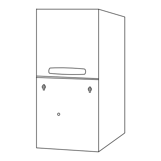
Page 5: Outline Drawings
Installer’s Guide 18-CD33D1-4... - Page 6 Installer’s Guide 18-CD33D1-4...
-
Page 7: Upflow Installation
Installer’s Guide UPFLOW INSTALLATION Standoffs and screws (See Figure 1) are included with A (width) the cased coils for attachment to the furnace. There are B (depth) clearance alignment holes near the bottom of the coil FURNACE wrapper. Drill screws are used to engage the furnace top FRONT flanges. -
Page 8: Air For Combustion And Ventilation
Installer’s Guide The furnace may be placed horizontally in a crawl space made in accordance with latest edition of Section 5.3, Air on a pad or other noncombustible material which will for Combustion and Ventilation, of the National Fuel Gas raise the unit for sufficient protection from moisture. - Page 9 Installer’s Guide MINIMUM AREA IN SQUARE FEET FOR UNCONFINED SPACE INSTALLATIONS FURNACE MAXI- WITH 8 FT. CEILING MUM BTUH INPUT MINIMUM AREA IN SQUARE FEET RATING OF UNCONFINED SPACE 60,000 80,000 100,000 120,000 1. All air from inside the building as in Figure 8: The confined space shall be provided with two perma- nent openings communicating directly with an addi- tional room(s) of sufficient volume so that the com-...
-
Page 10: Duct Connections
Installer’s Guide DUCT CONNECTIONS PREPARATION FOR UPFLOW BOTTOM AND SIDE Air duct systems should be installed in accordance with RETURN AIR FILTER INSTALLATION standards for air conditioning systems, National Fire All return air duct systems should provide for installation Protection Association Pamphlet No. 90. They should be of return air filters. -
Page 11: Return Air Filters
Installer’s Guide 9. The horizontal installation of the upflow furnace TABLE 3 requires an external filter section. Do NOT use UPFLOW FURNACE RETURN AIR FILTERS the bottom return filter within the furnace. Filter CABINET kits are available for horizontal applications. CABINET CABINET QTY*... - Page 12 Installer’s Guide ALTERNATE FILTER RACK INSTALLATION FOR SIDE RETURN AIR ON UPFLOW FURNACES (Left or Right) Furnace Engagement Hole Blower Filter Rack BAYRACK960 Installation With BLOWER Deck Side Return DECK The following checklist should be used when installing a right or left side return filter on an upflow furnace: Furnace Cabinet a.
- Page 13 Installer’s Guide UPFLOW FILTER CLIP/BRACKET INSTALLATION TYPICAL DOWNFLOW FURNACE RETURN 1. Determine the location to be used. The furnace cabi- FILTER INSTALLATIONS net has dimples for location of the alternate furnace These furnaces require high velocity type air filters. clips (Side return only). Pre-drill clearance holes with Downflow furnace filters must be located outside the a 3/16"...
-
Page 14: General Venting Instructions
Installer’s Guide GENERAL VENTING venting system are located and other spaces of the building. Turn on clothes dryers and any appliances THIS FURNACE MUST BE VENTED TO THE OUT- not connected to the common venting system. Turn DOORS. THESE FURNACES ARE INDUCED DRAFT on any exhaust fans, such as range hoods and bath- VENTED AND MUST NOT BE CONNECTED TO ANY room exhausts, so they will operate at maximum... -
Page 15: Venting Material
Installer’s Guide PVC VENT FITTING MATERIAL socket and pipe with cleaner-primer. Apply a liberal These fittings are available from your Gas Furnace coat of primer to inside surface of socket and outside Distributors. of pipe. DO NOT ALLOW PRIMER TO DRY BEFORE AP- Straight Pipe Sections, Couplings, 45°... -
Page 16: Horizontal Venting
Installer’s Guide VENT AND INLET AIR CONNECTIONS WHEN THE FACTORY SUPPLIED "OFF-SET" (2X3 REDUCING COUPLING) IS USED FOR 3" VENT PIPE Seal VENT PIPE INSTALLATION, MAKE SURE THE MARKING "TOP" IS with RTV sealant LOCATED ON THE TOP SIDE OF THE PIPE. LABEL SAYS "TOP"... - Page 17 Installer’s Guide TABLE 8 - UPFLOW/ HORIZONTAL VENTING TABLE MAXIMUM VENT LENGTH: DIRECT VENT (2 PIPE SYSTEM) - NONDIRECT VENT (1 PIPE SYSTEM) -MAXIMUM TOTAL MAXIMUM TOTAL EQUIVALENT FEET FOR EQUIVALENT FEET FOR VENT PIPES ONLY (See Notes) VENT AND INLET AIR PIPES (See Notes) MODEL 2"...
- Page 18 Installer’s Guide INSIDE CORNER DETAIL VENT TERMINAL X AIR SUPPLY INLET AREA WHERE TERMINAL IS NOT PERMITTED Direct Vent Terminal Clearances Canadian Installations US Installations Clearance above grade, veranda, porch, deck, or 12 inches (30 cm) 12 inches (30 cm) balcony 6 inches (15 cm) for appliances =/<...
- Page 19 Installer’s Guide Non-Direct Vent Terminal Clearances Canadian Installations US Installations Clearance above grade, veranda, porch, deck, or 12 inches (30 cm) 12 inches (30 cm) balcony 6 inches (15 cm) for appliances =/< 10,000 Btuh (3 kw), 12 4 feet (1.2m) below or to the side inches (30 cm) for appliances >...
-
Page 20: Venting Through The Wall
Installer’s Guide Shield material to be a minimum of 24 gauge stainless CAUTION or aluminized sheet metal. Minimum dimensions are When the vent pipe is exposed to temperatures below 12"x12". Shield must be fastened to both inside and out- freezing, i.e., when it passes through unheated spaces, side of wall. - Page 21 Installer’s Guide PVC WALL COUPLING MOUNT FLANGE (PLASTIC (OPTIONAL) SUPPORT HORIZONTAL PIPE EVERY VENTING) 3' 0" WITH THE FIRST SUPPORT AS 6 IN. MIN. APPROVED CLOSE TO THE FURNACE AS POSSIBLE. (TO JOINT) TERMINATION INDUCED DRAFT BLOWER, HOUSING, AND FURNACE MUST NOT SUPPORT THE WEIGHT OF THE FLUE PIPE.
-
Page 22: Downward Venting
Installer’s Guide NOTE: DOWNWARD VENTING Both venting methods shown in Figure 30 & 31 must Furnace may be in vertical also have the combustion air inlet installed - meeting or horizontal configuration. dimension requirements of Figure 21. DOWNWARD VENT LENGTH IS LIMITED TO A MAXIMUM OF 15 EQUIVALENT FEET. - Page 23 Trane 1. INSTALLATION OF CARBON MONOXIDE DETECTORS. 6200 Troup Highway At the time of installation of the side wall horizontal vented...
- Page 24 Installer’s Guide SEAL BETWEEN FLANGE, PIPE, COUPLING AND METAL PANEL WITH HI TEMP RTV SILICONE SEALANT FLUE PIPE COUPLING SUPPORT FLANGE CEILING GALVANIZED FIRESTOP SHOULD BE FABRICATED WITH 3-7/8" DIA. HOLE FOR SUPPORT FLANGE (12" x 12" PANEL OR 12" DIA MIN.) CLEARANCE ( 0"...
-
Page 25: Condensate Drain Instructions
Installer’s Guide CONDENSATE DRAIN INSTRUCTIONS Downflow furnace - Use RTV silicon sealant to connect the fitting to the trap for ease of removal when cleaning CAUTION the trap. For left side drain a 1/2" slip PVC fitting is needed. See IT IS RECOMMENDED THAT A DRAIN PAN BE INSTALLED Figure 44. - Page 26 Installer’s Guide pan to a separate drain line (no trap is needed in this line). The trap must be repositioned to the exterior of the cabi- net. Remove the trap from its present location and reposi- tion the trap outside of the unit, through the long circular hole, next to the secondary recuperative cell.
-
Page 27: Electrical Connections
Installer’s Guide ELECTRICAL CONNECTIONS & Make wiring connections to the unit as indicated on en- closed wiring diagram. As with all gas appliances using electrical power, this furnace shall be connected into a permanently live electric circuit. It is recommended that furnace be provided with a separate “circuit protection device”... - Page 28 Installer’s Guide FIELD WIRING DIAGRAM FOR 1 STAGE FURNACE 1 STAGE HEATING, 1 STAGE COOLING USING A 1 STAGE HEATING, 1 STAGE COOLING THERMOSTAT (OUTDOOR SECTION WITHOUT TRANSFORMER) FURNACE OUTDOOR UNIT (NO TRANSFORMER) NOTE 6 NOTE 8 TO 115 V 1 PH., 60 HZ., POWER SUPPLY PER LOCAL CODES...
-
Page 29: Gas Piping
Installer’s Guide TWINNING CONNECTION DIAGRAM FOR TWINNING 1 STAGE FURNACES WITH SINGLE WIRE TWINNING FEATURE 1 STAGE HEAT / 1 STAGE COOL THERMOSTAT 1 STAGE OUTDOOR UNIT HEATING / COOLING (WITH TRANSFORMER) THERMOSTAT FURNACE NO. 1 FURNACE NO. 2 BLOWER OPERATION OF UNIT NO. - Page 30 Installer’s Guide AUTOMATIC GAS VALVE AUTOMATIC GAS VALVE WITH MANUAL SHUTOFF WITH MANUAL SHUTOFF MAIN MANUAL SHUTOFF VALVE MAIN MANUAL SHUTOFF VALVE GROUND UNION JOINT GROUND UNION JOINT DRIP DRIP UPFLOW – LEFT HAND GAS PIPING UPFLOW – RIGHT HAND GAS PIPING THE DOWNFLOW (VERTICAL) MAY BE INSTALLED LEFT OR RIGHT SIDE GAS PIPING MAIN MANUAL AUTOMATIC GAS VALVE WITH...
-
Page 31: Combustion Input Checks
Installer’s Guide CAUTION 6. Multiply the final figure by the heating value of the gas obtained from the utility company and compare Use a backup wrench on the gas valve when install- to the nameplate rating. This must not exceed the ing gas piping to prevent damage to the gas valve and nameplate rating. - Page 32 Installer’s Guide CAUTION Input rate changes can be made by adjusting the mani- fold pressure (min 3.0 - max 3.7 in. W.C. - Natural Gas) or Replace and/ or tighten all plugs removed or loosened changing orifices (orifice change may not always be re- when adjusting gas pressure.
-
Page 33: Start Up And Adjustment
Installer’s Guide Orifice TABLE 15 ROTATE THE FRONT Twist Drill ALTITUDE ABOVE SEA LEVEL COVER AS SHOWN Size If and Orifice Required At Other Elevations Installed At Sea INSERT THE TOP Level 2000 3000 4000 5000 6000 7000 8000 9000 10000 FLANGE OF THE FRONT COVER UN- DER THE LIP INSIDE... -
Page 34: Lighting Instructions
Installer’s Guide SEQUENCE OF OPERATION Thermostat call for heat Regulator Outlet Pressure Boss R and W thermostat contacts close signaling the con- Adjustment trol module to run its self-check routine. After the control module has verified that the pressure switch contacts are open and the limit switch(es) contacts are closed, the draft blower will be energized. -
Page 35: Airflow Adjustment
Installer’s Guide AIRFLOW ADJUSTMENT CONDITIONS AFFECTING FURNACE OPERATION 1. EXCESSIVE COMBUSTION PRESSURE (WIND IN Check inlet and outlet air temperatures to make sure they are within the ranges specified on the furnace rat- EXCESS OF 40 M.P.H.) VENT OR FLUE BLOCK- ing nameplate. - Page 36 Gas valve circuit error 8 Flashes --- Low flame sense signal Check Ignitor Circuit and Line "N" to 24VAC "Common" voltage (< 2 volts) 9 Flashes --- [possible grounding problem] Trane Literature Order Number 18-CD33D1-4 6200 Troup Highway File Number 18-CD33D1-4...