Advertisement
ALL phases of this installation must comply with NATIONAL, STATE AND LOCAL CODES
IMPORTANT — This Document is customer property and is to remain with this unit.
*DD2-9V
Downflow / Horizontal*
*Horizontal Conversion for these furnaces may be left or right side rotation.
Installer's Guide
Variable Speed, 2-Stage
Upflow / Horizontal and
Downflow / Horizontal, Gas-Fired Furnaces,
"Fan Assisted Combustion System"
*UD2B060A9V3VB
*UD2B080A9V3VB
*UD2C080A9V4VB
*UD2C080B9V4VB
*UD2B100A9V3VB
Please return to service information pack upon completion of work.
For VENT SIZING INFORMATION see:
USA —
National Fuel Gas Code ........... ANSI Z223.1/NFPA 54 (latest version)
CANADA —
Natural Gas Installation Code ........CAN/CGA-B149.1 (latest version)
Propane Installation Code ...............CAN/CGA-B149.2 (latest version)
USA/CANADA ALTERNATE —
Category I Venting Guide ...........Pub. No. 18-CH23D1 (latest version)
1 8- CD31 D1 - 5
*UD2C100A9V5VB
*UD2C100B9V5VB
*UD2D120A9V5VB
*UD2D120B9V5VB
*UD2D140A9V5VB
*UD2-9V
Upflow / Horizontal*
18-CD31D1-5
*DD2B060A9V3VA
*DD2B080A9V3VA
*DD2C100A9V5VA
*DD2D120A9V5VA
*__First letter may be "A" or "T"
A341789P10
Advertisement
Table of Contents

Related Manuals for Trane *UD2B060A9V3VB


Summary of Contents for Trane *UD2B060A9V3VB
- Page 1 1 8- CD31 D1 - 5 18-CD31D1-5 Installer’s Guide Variable Speed, 2-Stage Upflow / Horizontal and Downflow / Horizontal, Gas-Fired Furnaces, “Fan Assisted Combustion System” *UD2B060A9V3VB *UD2C100A9V5VB *DD2B060A9V3VA *UD2B080A9V3VB *UD2C100B9V5VB *DD2B080A9V3VA *UD2C080A9V4VB *UD2D120A9V5VB *DD2C100A9V5VA *UD2C080B9V4VB *UD2D120B9V5VB *DD2D120A9V5VA *UD2B100A9V3VB *UD2D140A9V5VB *__First letter may be “A” or “T” ALL phases of this installation must comply with NATIONAL, STATE AND LOCAL CODES IMPORTANT —...
-
Page 2: Safety Section
Gas Fitter in the Commonwealth of Massachusetts. Failure to follow the safety warnings exactly could result in serious injury, death or property damage. Improper servicing could result in dangerous operation, serious injury, death, or property damage. 18-CD31D1-5 © 2011 Trane All Rights Reserved... -
Page 3: Table Of Contents
Installer’s Guide Contents GENERAL INSTALLATION INSTRUCTIONS The manufacturer assumes no responsibility for equipment installed in violation of any code or regulation. Installation Instructions It is recommended that Manual J of the Air Conditioning Contractors Association (ACCA) or A.R.I. 230 be followed General Installation Instructions in estimating heating requirements. - Page 4 Installer’s Guide 18-CD31D1-5...
- Page 5 Installer’s Guide 18-CD31D1-5...
-
Page 6: Outline Drawing
Installer’s Guide TABLE 1 7. A furnace shall be installed so electrical components are protected from water. FLOOR OPENING PLENUM OPENING CABINET RETURN WIDTH DUCT WIDTH "A" "B" "C" "D" 8. If the furnace is installed in a residential garage, it must be installed so that the burners, and the ignition 17-1/2"... -
Page 7: Air For Combustion And Ventilation
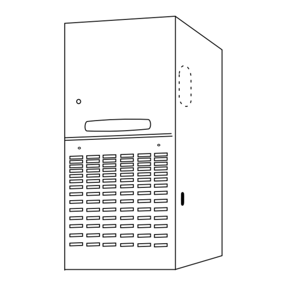
Installer’s Guide A cutout is provided on both sides of the downflow fur- nace cabinet to allow a 90° elbow to be attached inside the UNCONFINED cabinet and the vent piping to connect there. In horizontal, the downflow furnace may be vented through the top of the 50 CU. -
Page 8: Duct Connections
Installer’s Guide TABLE 3 DUCT CONNECTIONS Air duct systems should be installed in accordance with MINIMUM FREE AREA IN SQUARE INCHES standards for air conditioning systems, National Fire Pro- EACH OPENING (FURNACE ONLY) tection Association Pamphlet No. 90. They should be sized Furnace in accordance with ACCA Manual D or whichever is appli- Air From Outside... - Page 9 Installer’s Guide 2. The return air filter is shipped in either the bottom or 6. If a 3/4" flange is to be used for attaching the air inlet side location. Remove the filter by first turning the two duct, add to cut where indicated by dotted lines in latches on the blower door and tilting the door forward Figure 12.
-
Page 10: Return Air Filters
Installer’s Guide RETURN AIR FILTERS ALTERNATE FILTER RACK INSTALLATION FOR BOTTOM RETURN TYPICAL UPFLOW RETURN AIR FILTER INSTALLATIONS Filters are factory supplied for these furnaces. These The following checklist should be used when installing a furnaces require high velocity type air filters. The filters bottom return filter on an upflow furnace: may be located within the furnace blower compartment for UPFLOW furnaces in either a BOTTOM or SIDE (left side... - Page 11 Installer’s Guide ALTERNATE FILTER RACK INSTALLATION FOR SIDE RE- TURN AIR ON UPFLOW FURNACES (LEFT OR RIGHT) The following checklist should be used when installing a Furnace Engagement Hole BLOWER right or left side return filter in an upflow furnace: Blower Filter Rack Installation With...
- Page 12 Installer’s Guide INSTALLING THE FILTER RETURN AIR FILTERS FOR UPFLOW FURNACE The filter may need to be cut to fit the unit depending on IN HORIZONTAL CONFIGURATION the location of the return air filter. When the Upflow Furnace is installed in the horizontal con- figuration, the return air filters must be installed exterior A score line and the words “CUT HERE”...
-
Page 13: General Venting Instructions
Installer’s Guide VENT PIPING TABLE 5 These furnaces have been classified as Fan-Assisted CABINET FILTER FILTER BRACKET Combustion System, Category I furnaces under the “lat- WIDTH SIZE LOCATION * est edition” provisions of ANSI Z21.47 and CAN/CGA 2.3 17-1/2" 2 - 16X20X1 14-3/8"... - Page 14 Installer’s Guide NOTE: TABLE 8 The following section does not apply if BAYVENT800B (Masonry Chimney Vent Kit) is used. All instructions with GAS VENT TERMINATION the kit must be followed. TABLE 7 ROOF PITCH MINIMUM HEIGHT MASONRY CHIMNEY VENTING Chimney Lining Tile Lined Chimney FLAT TO 7/12 1.0 FEET *...
-
Page 15: Electrical Connections
Installer’s Guide ELECTRICAL CONNECTIONS WARNING The cabinet must have an uninterrupted or unbroken ground according to National Electrical Code, ANSI/ NFPA 70 - “latest edition” and Canadian Electrical Code, CSA C22.1 or local codes to minimize personal injury if an electrical fault should occur. -
Page 16: Field Wiring Diagrams
Installer’s Guide FIELD WIRING DIAGRAMS 18-CD31D1-5... -
Page 17: Field Wiring Diagrams
Installer’s Guide FIELD WIRING DIAGRAMS 18-CD31D1-5... -
Page 18: Gas Piping
Installer’s Guide GAS PIPING WARNING WARNING FIRE OR EXPLOSION HAZARD FIRE - EXPLOSION HAZARD Failure to follow the safety warnings exactly could result DO NOT RUN FLEXIBLE GAS LINE THROUGH THE FUR- in serious injury, death or property damage. NACE CABINET WALL. FAILURE TO FOLLOW THIS WARN- Never test for gas leaks with an open flame. - Page 19 Installer’s Guide 6. Multiply the final figure by the heating value of the gas WARNING obtained from the utility company and compare to the Explosion Hazard nameplate rating. This must not exceed the nameplate Replace and/or tighten all plugs removed or loosened rating.
-
Page 20: High Altitude Derate
Installer’s Guide TABLE 9 Important: Reinstall the propane orifices to the same depth as the orifices FINAL MANIFOLD PRESSURE SETTINGS (inches w.c.) supplied with the equipment. FUEL 2nd Stage Max. 1st Stage Max. See Table 14 for help in selecting orifices if orifice change is required. -
Page 21: Preliminary Inspections
Installer’s Guide SEQUENCE OF OPERATION WARNING Thermostat call for heat (2-stage thermostat) DO NOT attempt to manually light the burner. Failure to Call for 1st stage only: follow this warning could result in property damage, per- R and W1 thermostat contacts close signaling the control sonal injury or death. -
Page 22: Control And Safety Switch Adjustment
Installer’s Guide INDOOR BLOWER TIMING WARNING Heating: The Integrated Furnace Control (IFC) controls the variable speed indoor blower. The blower “on” time is EXPLOSION HAZARD! fixed at 45 seconds after ignition. The FAN-OFF period PROPANE GAS IS HEAVIER THAN AIR AND MAY COL- is field selectable by dip switches S7-3 and S7-4 on the LECT IN ANY LOW AREAS OR CONFINED SPACES. - Page 23 Installer’s Guide ABNORMAL CONDITIONS The following warning complies with State of California law, Proposition 65. 1. EXCESSIVE COMBUSTION PRESSURE (WIND IN WARNING EXCESS OF 40 M.P.H.) VENT OR FLUE BLOCKAGE If pressure against induced draft blower outlet becomes This product contains fiberglass wool insulation! excessive, the pressure switch will open and shut off the gas valve until acceptable combustion pressure is Fiberglass dust and ceramic fibers are believed by the...
- Page 24 See Service Facts for additional troubleshooting information. Literature Order Number 18-CD31D1-5 File Number 18-CD31D1-5 Supersedes 18-DC31D1-4 Trane Date 06/11 6200 Troup Highway Tyler, TX 75707 Since the manufacturer has a policy of continuous product and product data improvement, it reserves the For more information contact right to change design and specifications without notice.