
Related Manuals for Toshiba e-Studio 162


Summary of Contents for Toshiba e-Studio 162
- Page 1 MULTIFUNCTIONAL DIGITAL SYSTEMS e-STUDIO162/162D e-STUDIO151/151D File No. SME04003200 R04112171700-TTEC Ver00_2005-01...
- Page 2 © 2005 TOSHIBA TEC CORPORATION All rights reserved Parts marked with “ ” are important for maintaining the safely of the machine. Be sure to replace these parts with the replacement parts specified to maintain the safety and performance of the machine.
- Page 3 GENERAL PRECAUTIONS REGARDING THE INSTALLATION AND SERVICE FOR e-STUDIO162/162D/151/151D The installation and service should be done by a qualified service technician. 1. Transportation/Installation • When transporting/installing the machine, be sure to use the positions as indicated below. The machine is quite heavy and weighs approximately 16.8 kg (37 lb.), therefore pay full attention when handling it.
- Page 4 Be sure to handle/install them properly. If these parts are shorted circuit and/or made their functions out, they may burn down, for instance, and may result in fatal accidents. Do not allow a short circuit to occur. Do not use the parts not recommended by Toshiba TEC Corporation. Cautionary Labels •...
- Page 5 CAUTION This product is a class 1 laser product that complies with 21CFR 1040 of the CDRH standard and IEC825. This means that this machine does not produce hazardous laser radiation. The use of controls, adjustments or performance of procedures other than those specified herein may result in hazardous radiation exposure.
- Page 6 At the production line, the output power Caution of the scanner unit is adjusted to 0.57 This product contains a low power laser MILLI-WATT PLUS 20 PCTS and is device. To ensure continued safety do not maintained constant by the operation of remove any cover or attempt to gain access the Automatic Power Control (APC).
-
Page 7: Table Of Contents
CONTENTS [1] GENERAL B. Disassembly procedure....... . . 8-7 C. Assembly procedure ........8-9 1. -
Page 8: Major Functions
[1] GENERAL 1. Major functions Configurations Item CPM / Color IEEE External ADF R-ADF Scanner SPLC E-SORT Duplex Shifter FAX DDM USB RJ45 Tray printer 1284 (push) Model ❍ ✕ ❍ ❍ ✕ ❍ ❍ ❍ ❍ ✕ e-STUDIO162 MB Opt e-STUDIO151 (2.0) ❍... -
Page 9: Basic Specifications
[2] SPECIFICATIONS 1. Basic Specifications Item Type Desktop Copy system Dry, electrostatic Segment (class) Digital personal copier Copier dimensions 20.4"(W) x 19.8"(D) x 11.7"(H) (518mm(W) x 503mm(D) x 296mm(H)) Weight (Approximately) e-STUDIO162/151 Approx. 36.6lbs. (16.6kg) e-STUDIO162D/151D Approx. 37.1lbs. (16.8kg) 2. Operation specifications Section, item Details Paper feed... -
Page 10: Copy Performance
Section, item Details Fusing section Fusing system Heat roller system Upper heat roller type Teflon roller Lower heat roller type Silicon rubber roller Heater lamp type Halogen lamp Voltage 230V Power consumption 800W Electrical section Power source Voltage Local voltage Frequency 50/60Hz Rated current... -
Page 11: Scan Function
4. SPLC printer Print speed Max. 15ppm (A4 / with ROPM) / 16ppm (Letter / with ROPM) First print time 9.6 sec. (without data transfer time) Duplex Yes (e-STUDIO162D/151D) ROPM None Memory Share the memory with E-SORT function Interface IEEE1284 / USB 2.0 Network External NIC (Optional) Emulation... -
Page 12: Supply List
[3] CONSUMABLE PARTS 1. Supply list A. Europe/SCA/SCNZ Item Content Life Product name Package Remark × 10 ∗ Life setup is based on A4 Toner CA (Black) Toner PS-ZT1200 × 10PLS (Toner: Net Weight 243g) × 10 Polyethylene bag × 1 Developer Developer D-1200... -
Page 13: Toner Cartridge Replacement
<Drum cartridge> <Developer> The label on the drum cartridge shows the date of production. Sub lot Production day Production month Production month Production day Destination code End digit of year (Dealer, distributor, OEM, etc.) Production place Production place 4. Toner cartridge replacement End digit of year Version No. -
Page 14: Appearance
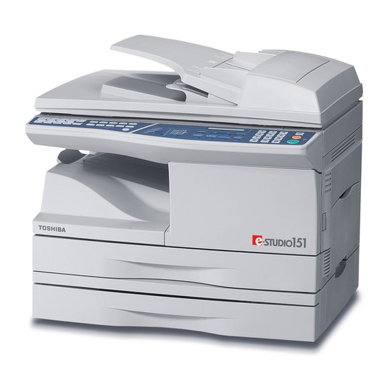
[4] EXTERNAL VIEWS AND INTERNAL STRUCTURES 1. Appearance (With optional ADF/RADF installed) Interface ADF/RADF (Option) Document glass Operation panel Front cover Paper tray Side cover Side cover open button Bypass tray paper guides Bypass tray Reversing tray (RADF only) 10 Original guides Document feeder cover 12 Document feeder tray 13 Exit area... -
Page 15: Operation Panel
3. Operation panel (e-STUDIO151/151D (Europe)) MENU Display ZOOM 1,2,3, 1,2,3, SP. FUNC READY TO COPY. 100% 6 7 8 9 10 11 12 13 14 16 17 (e-STUDIO162/162D) Display READY TO COPY. 100% 8.5x11 8 9 10 11 12 13 14 16 17 1 [MODE SELECT] key / Mode indicators 2 Display... -
Page 16: Motors And Solenoids
4. Motors and solenoids (With optional ADF/RADF installed) Part name Control signal Function / Operation Main motor Drives the copier. Scanner motor MRMT Drives the optical mirror base (scanner unit). Toner motor Supplies toner. Cooling fan motor Ventilate the fuser section. Resist roller solenoid Resist roller rotation control solenoid Paper feed solenoid... -
Page 17: Sensors And Switches
5. Sensors and switches (With optional ADF/RADF installed) Name Signal Type Function Output Scanner unit home position MHPS Photointerrupter Scanner unit home position detection "H" at home position sensor POD sensor Photointerrupter Paper exit detection "H" at paper pass PPD2 sensor PPD2 Photointerrupter Paper transport detection 2... -
Page 18: Pwb Unit
6. PWB unit (With optional ADF/RADF and FAX installed) Name Function Exposure lamp inverter PWB Exposure lamp (CCFL) control Main PWB (MCU) Copier control Operation PWB Operation input/display Power PWB AC power input, DC voltage control, High voltage control CCD sensor PWB For image scanning LSU motor PWB For polygon motor drive (In the LSU) -
Page 19: Cross Sectional View
7. Cross sectional view (With optional RADF installed) Part name Function and operation Scanner unit Illuminates the original with the copy lamp and passes the reflected light to the lens unit(CCD). Exposure lamp Exposure lamp (CCFL) Illuminates original LSU (Laser unit) Converts the original image signal into laser beams and writes onto the drum. -
Page 20: Cautions On Handling
[5] UNPACKING AND INSTALLATION 2. Cautions on handling Be careful in handling the copier as follows to maintain the perfor- 1. Copier installation mance of this copier. Do not drop the copier, subject it to shock or strike it against any Improper installation may damage the copier. -
Page 21: Developer Unit Installation
4. Unpacking 4) Remove the CAUTION tape from the front cover and remove the two protective pins from the fusing machine by pulling the strings Be sure to hold the handles on both sides of the machine to unpack the upward one at a time. -
Page 22: Toner Cartridge Installation
9) Shake the aluminum bag to stir developer 7. Toner cartridge installation 10) Supply developer from the aluminum bag to the top of the MX 1) To prevent against uneven distribution of toner, hold Toner unit with roller evenly. both hands and shake it several times horizontally. 2) Hold the section of Toner unit shown in the figure below, remove the packing tape, and remove the cushion. -
Page 23: Loading The Paper Tray
8. Loading the paper tray Note: Make sure that the paper is not torn, is free of dust, and has no wrinkles or curled edges. 1) Raise the handle of the paper tray and pull the paper tray out until it stops. -
Page 24: A. Before Installation
A. Before Installation B. Installing the software Note: (1) Hardware and software requirements • If you need to use a different connection method after installing the Check the following hardware and software requirements in order to software based on a USB or parallel connection, you must first unin- install the software. - Page 25 8) When the "Finish" screen appears, click the "Close" button. 7) Click the "Custom" button. A message will appear instructing you to connect the machine to your computer. Click the "OK" button. Caution: If you are running Windows 2000/XP and a warning message appears regarding the Windows logo test or digital signature, be sure to click "Continue Anyway"...
- Page 26 11) You will return to the window of step 8). If you wish to install Button Man- 14) Make sure that the power of the machine is turned on, and then ager or Desktop Document Manager, click the "Utility Software" button. connect the USB/parallel cable.
- Page 27 5) When you are asked how the printer is connected, select "Con- (3) Windows 95/98/Me/NT 4.0/2000 (Parallel) nected to this computer" and click the "Next" button. 1) The parallel cable must not be connected to the machine. Make sure that the cable is not connected before proceeding. If the cable is connected, a Plug and Play window will appear.
- Page 28 7) Select the printer port and whether the machine is to be used as the 2) Click the "MFP Driver" button. default printer, make the selections and click the "Next" button. To view detailed information on the software, click the "Display Select "LPT1"...
-
Page 29: C. Setting Up Button Manager
Ask your network administrator for the server name and printer name of the machine on the network. 5) Select "Start this program" and then select "TOSHIBA Button Man- 7) In the printer port selection window, verify the network printer that is ager E"... -
Page 30: D. Connecting The Machine To Your Computer
USB 2.0 (Hi-Speed) only if the Microsoft USB 2.0 driver is preinstalled in the computer, or if the USB 2.0 driver for Windows 6) Select "TOSHIBA Button Manager E" in "Send to this application". 2000 Professional/XP that Microsoft provides through its "Windows Update"... -
Page 31: Interface
11. Interface Pin No. Signal name Pin No. Signal name GND (STB RET) A. USB DATA1 GND (DATA1 RET) Connector DATA2 GND (DATA2 RET) DATA3 GND (DATA3 RET) 4-pin ACON UBR23-4K2200 DATA4 GND (DATA4 RET) Type-B connector DATA5 GND (DATA5 RET) Cable DATA6 GND (DATA6 RET) -
Page 32: Functional Diagram
[6] COPY PROCESS An OPC drum is used for the photoconductor. (Structure of the OPC drum layers) OPC layer (20 microns thick) Pigment layer (0.2 to 0.3 microns thick) Aluminum drum 1. Functional diagram Main charger Laser beam Cleaning blade MG roller Drum Transfer unit... -
Page 33: Outline Of Print Process
2. Outline of print process Step-2: Exposure (laser beam, lens) A Laser beam is generated from the semiconductor laser and This printer is a non-impact printer that uses a semiconductor laser controlled by the print pattern signal. The laser writes onto the OPC and electrostatic print process. - Page 34 Step-3: Developing (DC bias) Step-4: Transfer A bias potential is applied to the MG roller in the two component The visible image on the drum surface is transferred onto the print magnetic brush developing method, and the toner is charged negative paper by applying a positive charge from the transfer corona to the through friction with the carrier.
- Page 35 Start Step-7: Optical discharge (Semiconductor laser) Before the drum rotation is stopped, the semiconductor laser is 1) Because the grid potential is at a low level, the drum potential is at radiated onto the drum to reduce the electrical resistance in the OPC about -400V.
-
Page 36: Outline Of Operation
[7] OPERATIONAL DESCRIPTIONS 1. Outline of operation The outline of operation is described referring to the basic configuration. (Basic configuration) (Option) FAX modem Scanner section Operation (Option) section Network Network FAX I/F Printer/ MCU (Main control/image process section) Scanner I/F USB or parallel Note: The scanner function is effective only by USB connection. -
Page 37: Scanner Section
2. Scanner section A. Scanner unit The scanner unit in the digital copier scans images. It is composed of the optical unit and the drive unit. The optical unit performs scanning in the main scan direction with the light receiving elements (color CCD). -
Page 38: Laser Unit
3. Laser unit B. Laser beam path The image data sent from the MCU (image process circuit) is sent to the LSU (laser unit), where it is converted into laser beams. A. Basic structure The LSU unit is the writing section of the digital optical system. The semiconductor laser is used as the light source, and images are formed on the OPC drum by the polygon mirror and f θ... -
Page 39: A. General Description
A. General description 2) The surface temperature of the upper heat roller is set to 165 - 190°C. The surface temperature during the power save mode is General block diagram (cross section) set to 100°C. Thermal fuse Separator pawl 3) The self-check function comes active when one of the following malfunctions occurs, and an "H"... - Page 40 (1) Cassette paper feed operation 5) At this time, the paper is fed passed the paper entry detection switch (PPD1), and detected by it. After about 0.15 sec from 1) The figure below shows the positions of the pick-up roller, the detection of paper by PPD1, the tray paper feed solenoid (PFS) paper feed clutch sleeve, and the paper feed latch in the initial turns on so that the clutch sleeve projection comes into contact...
- Page 41 (2) Manual multi paper feed operation 3) When pawl C of the manual paper feed clutch sleeve is engaged with the manual feed latch, the manual feed stopper falls and the 1) Before paper feed operation, the manual paper feed solenoid manual take-up roller rises.
-
Page 42: A. Initial State
(3) Conditions of occurrence of paper misfeed a. When the power is turned on: PPD or POD is ON when the power is turned on. b. Copy operation a PPD1 jam PPD1 does not turn off within 4 sec after turning on the resist roller. -
Page 43: Shifter
7. Shifter Shift width: 2.5cm The offset function by the shifter is turned ON/OFF by the user pro- gram. According to the setting, offset operation is performed for every job. (Default: ON) Switchback operation is made after back copying in order to discharge documents according to the setting. -
Page 44: High Voltage Section
[8] DISASSEMBLY AND ASSEMBLY 2) Remove the drum fixing plate and the photoconductor drum. (Note) Dispose the drum fixing plate which was removed. Before disassembly, be sure to disconnect the power cord for safety. 1. Do not disconnect or connect the connector and the har- ness during the machine is powered. - Page 45 5) Remove the cleaning blade. Attach the mocket with slightly pressing section A of the cleaning blade. Note: Dispose the cleaning blade which was removed. Do not touch the tip of the cleaning blade. Do not put the mocket under the cleaning blade. Do not put the mocket on the sub blade.
-
Page 46: C. Disassembly Procedure (Transfer Charger Unit)
12) Attach the detection gear. 2) Push up the lock pawls (2 positions) of the side cover, and remove the transfer charger. Note: • The detection gear is not installed to the drum cartridge packed Lock pawl rear with the main body. Add a new one. 13) Attach the drum cover. -
Page 47: F. Charger Wire Replacement
2) Set the charger cleaner to the transfer unit, and move it recipro- 2. Operation panel section cally a few times in the direction of the arrow shown in the figure A. List below. Part name Ref. Operation panel unit Operation PWB B. -
Page 48: Optical Section
3) Remove four screws, and remove the operation cabinet. 2) Remove the four screws, remove the operation unit, and discon- nect the connector. 4) Remove four screws, and remove the operation PWB. 3) Remove the right cabinet. 4) Remove the left cabinet. 5) Remove the screw, and remove the rear cover. -
Page 49: C. Assembly Procedure
10) Remove the screw, and remove the rod stopper. C. Assembly procedure 11) Remove the rod. CCD core 1) Pass the core through the CCD-MCU harness. 2) Insert the CCD-MCU harness into the CCD PWB connector of the carriage unit. 3) Move the core which was passed through the CCD-MCU harness near the CCD PWB connector as shown in the figure below, and fix it with a filament tape (19mm wide, 40mm long). -
Page 50: Fusing Section
4. Fusing section 4) Remove the screw and remove the U-turn guide. A. List Part name Ref. Thermistor PPD2 sensor Heater lamp Pressure roller Heat roller B. Disassembly procedure 1) Remove the connectors (3 pcs.) of the rear cabinet. 2) Open the side cover, remove two screws, and remove the fusing unit. - Page 51 7) Remove the plate spring on the right and remove the heater lamp. 10) Remove the pressure release levers on the right and the left sides. 11) Remove the pressure roller, the pressure bearing, and the spring. Note: Apply grease to the sections specified with an asterisk (*). Grease: “JFE552”...
-
Page 52: C. Assembly Procedure
6) Remove the C-ring and the fusing bearing, and remove the heat 5. Tray paper feed/transport section roller. A. List Part name Ref. Heat roller Paper holding arm PPD1 sensor PWB LSU unit Intermediate frame unit Paper feed roller B. Disassembly procedure 1) Remove the paper holding arm. - Page 53 5) Disconnect the connector from the MCU PWB. 9) Disengage the pawl, and remove the roller knob. 6) Disengage the pawls (2 positions), and remove the sensor PWB. 10) Disengage the pawl, and shift the pulley and the bearing. 11) Remove the paper exit roller, and remove the belt, the pulley, and the bearing.
- Page 54 13) Remove the flat cable and the grounding wire. 18) Remove the three screws, and remove the DUP motor unit and the belt. 14) Remove the four screws, and remove the FAX PWB unit. (When the GD-1190 is installed) 19) Remove the harness guide. Caution: Be careful not to touch the sharp edge on the circumference of the metal frame the interface.
- Page 55 21) Remove the parts as shown below, and remove the pressure 23) Remove two screws and remove the fusing connector. release solenoid and the paper feed solenoid. 24) Remove five screws and the connector, and lift the intermediate frame unit to remove. 25) Remove the four screws, and remove the lower paper guide unit.
- Page 56 26) Disengage the pawl, and remove the pulley. 31) Remove the four screws, and remove the LSU. 27) Shift and remove the shifter unit. 28) Remove the screw, and remove the grounding plate and the gear. 29) Remove the E-ring, the gear, and the bearing, and remove the shifter roller.
-
Page 57: C. Assembly Procedure
32) Remove the screw and the E-ring, and remove the PS semi-circu- 36) Remove two E-rings and remove the paper feed roller. lar earth plate and the PS roller unit. 37) Remove three E-rings and remove the clutch unit. 33) Remove the E-ring and remove the spring clutch from the PS roller unit. -
Page 58: Manual Paper Feed Section
6. Manual paper feed section 3) Remove three screws and remove the multi paper feed upper frame. A. List Part name Ref. Manual transport roller Cassette detection switch PPD1 sensor PWB Side door detection unit B. Disassembly procedure Multi unit 1) Remove the screw and remove the multi upper cover. -
Page 59: C. Assembly Procedure
5) Remove three E-rings and remove the manual paper feed roller 7) Cut the binding band and remove the multi paper feed solenoid. Multi paper feed solenoid 6) Remove the pick-up roller. C. Assembly procedure For assembly, reverse the disassembly procedure. D. -
Page 60: Rear Frame Section
7. Rear frame section 7) Remove two screws and one connector, and remove the exhaust fan motor. A. List Note: Be careful of the installing directions of the fan. Attach it so that the blowing direction faces outside. Part name Ref. FAX PWB (When the GD-1190 installed) Mirror motor Main motor... -
Page 61: Power Section
8. Power section C. Assembly procedure For assembly, reverse the disassembly procedure. A. List 10. Reverse roller section (Duplex model Part name Ref. Power PWB only) A. List B. Disassembly procedure 1) Disconnect each connector. Part name Ref. 2) Remove the screw, and remove the earth line. Reverse roller 3) Remove two screws, and remove the power PWB unit. -
Page 62: Optical Section
[9] ADJUSTMENTS 5) Calculate the main scanning direction magnification ratio. Main scanning direction magnification ratio Copy image dimensions 1. Optical section X 100 (%) Original dimension A. Copy magnification ratio adjustment (When a 100mm scale is used as the original.) The copy magnification ratio must be adjusted in the main scanning Original (Scale) HARDENED... -
Page 63: B. Image Position Adjustment
2) Set the copy magnification ratio to 100%. Display Mode Default 3) Make a copy on A4 or 81/2" x 11" paper. item 4) Measure the length of the copied scale image. Print center offset TRAY1 COPY mode lamp (Main cassette paper Main cassette lamp 5) Calculate the sub scanning direction copy magnification ratio feed) -
Page 64: Copy Density Adjustment
(Example) Document guide Distance from the paper lead edge to the image lead edge, H = 5mm Image loss, R = 4mm 10mm 2) Execute TC 50-10 to select the print center offset (cassette paper feed) adjustment mode. The set adjustment value is displayed on the copy quantity display. 3) Make a copy and check that the copied center line is properly positioned. -
Page 65: C. Necessary Tool For Copy Density Adjustment
SCAN mode lamp copied. 3) Make a copy. Check the adjustment level (shown in the above table) of the exposure test chart (TOSHIBA Gray Scale). (When too bright): Decrease the value displayed on the copy quantity display. White paper (When too dark): Increase the value displayed on the copy quantity display. -
Page 66: High Voltage Adjustment
3. High voltage adjustment 4. Duplex adjustment (With optional RADF installed) A. Main charger (Grid bias) Note: A. Adjusting the paper reverse position in memory • Use a digital multi meter with internal resistance of 10M Ω or more for duplex copying measurement. -
Page 67: B. Adjusting Trailing Edge Void In Duplex Copy Mode
2) Set the test chart on the document glass as shown below. The trailing edge has a scale Document guide 2nd printing surface where scale is printed (lower side) B. Adjusting trailing edge void in duplex copy mode Table glass This is the adjustment of the first surface printing mode (rear end void) 3) Execute test command 50-19 to turn on the PRINT mode lamp and in duplex copying. -
Page 68: Radf (Adf) Mode Sub Scanning Direction Magnification Ratio Adjustment (With Optional Adf/Radf Installed)
5. ADF (RADF) scan position automatic 6. RADF (ADF) mode sub scanning adjustment (With optional ADF/RADF direction magnification ratio adjustment installed) (With optional ADF/RADF installed) Place a black chart so that it covers the ADF scan glass and the OC Note: Before performing this adjustment, be sure to check that the OC glass together, and close the OC cover. -
Page 69: Automatic Black Level Correction
7. Automatic black level correction a. Cases when the adjustment is required 1) When the main PWB is replaced. 2) When the EEPROM in the main PWB is replaced. 3) When "U2" trouble occurs. 4) When repairing or replacing the optical section. b. -
Page 70: Entering The Test Command Mode
[10] TEST COMMAND, TROUBLE CODES 1. Entering the test command mode To enter the serviceman test command mode, press the keys as follows: → → → [#] key [*] key [C] key [*] key To cancel the test command mode, press the [CA] key. 2. -
Page 71: Mag.)
Main Main Contents Contents code code code code JAM total counter clear (JAM TTL CLR.) Copier color reproduction setting (COLOR REAPPEAR) ADF counter clear (ADF CLR.) (Disabled when set to FAX mode sharpness adjustment (Executable only when OC) (Executable only when the ADF is installed.) the FAX is installed.) Duplex counter clear (DPLX CLR.) (Enabled when Mains can/sub scan direction magnification ratio (COPY... -
Page 72: Magnification Ratio
Main Contents code code Communication time measurement (Executable only when the FAX is installed.) Speaker sound volume setting (Executable only when the FAX is installed.) Time setting/check (Executable only when the FAX is installed.) CI signal check (Executable only when the FAX is installed.) 4. - Page 73 Main Contents Details of function/operation code code ADF sensor status display [Function] (ADF SENSOR) (Disabled The ON/OFF status of the ADF sensors can be checked with the LCD. when set to OC) (Executable When a sensor is ON, the sensor name is displayed on the LCD. only when the ADF is Sensor Display item...
- Page 74 Main Contents Details of function/operation code code Operation panel display [Function] check (LCD/LED CHK) <LED check mode (All ON/Individual ON)> When [OK (ENTER)/START] key is pressed, all the LCD's on the operation panel are turned ON (all pixels ON). After 5sec of ON, the machine goes into the sub code entry standby mode. When [MODE SWITCH] key is pressed under the all ON state, the mode is shifted to the individual ON mode, where the LED's are turned on one by one from the left upper end to the left lower side then from the right upper side to the right lower side.
- Page 75 Main Contents Details of function/operation code code Paper feed solenoid [Function] (CPFS1, CPFS2, MPFS) When [OK (ENTER)/START] key is pressed, the selected paper feed solenoid repeats ON for 500ms operation check (PSOL and OF for 500ms 20times. CHK) ← → When [ /10KEY] is pressed, the paper feed solenoid setting is switched.
- Page 76 Main Contents Details of function/operation code code Developing bias output [Function] (DVLP BIAS SET.) When [OK (ENTER)/START] key is pressed, the developing bias signal is turned ON for 30sec. When, however, an actual output value is measured, use test command 25-01. After completion of this process, the machine goes into the sub code entry standby mode.
- Page 77 Main Contents Details of function/operation code code Toner motor operation [Function] (TONER MOTOR) When [OK (ENTER)/START] key is pressed, the toner motor is rotated for 30sec. After completion of this process, the machine goes into the main code entry standby mode. [Operation] 1) Initial display 10-00 TONER MOTOR...
- Page 78 Main Contents Details of function/operation code code Maintenance preset display [Function] (M-CNT PRESET) The quantity (25,000 sheets, etc.) corresponding to the code set with TC21-01 is displayed. [Operation] 1) Initial display 22-02 M-CNT PRESET ***,*** JAM total counter display [Function] (JAM TTL CNT) The JAM total counter is displayed.
- Page 79 Main Contents Details of function/operation code code ROM version display (ROM [Function] VER.) The P-ROM version is displayed. ← → Press [ /10KEY] to switch the display version. Code number Version Display item Main unit Program MAIN PROG. F-IMC Program F-IMC PROG.
- Page 80 Main Contents Details of function/operation code code Scanner counter display [Function] (SCAN CNT) The scanner counter is displayed. [Operation] 1) Initial display 22-21 SCAN CNT ***,*** ADF JAM counter display (S [Function] JAM CNT) (Disabled when The ADF JAM counter is displayed. set to OC) (Executable only [Operation] when the ADF is installed.)
- Page 81 Main Contents Details of function/operation code code Printer counter clear [Function] (PRT.CLR.) When [OK (ENTER)/START] key is pressed, the printer counter value is cleared to 0, and "000,000" is displayed on the LCD. [Operation] 1) Initial display 24-09 PRT.CLR. CLEARED 000,000 FAX counter clear (FAX [Function]...
- Page 82 Main Contents Details of function/operation code code (R)ADF setting (ADF/RADF) [Function] (Executable only when the When this test command is executed, the current set ADF is displayed. Enter the code number corre- ADF/RADF is installed.) sponding to the desired ADF and press [OK (ENTER)/START] key to save the setting. Code number Display item ADF NO...
- Page 83 Main Contents Details of function/operation code code CE mark support control ON/ [Function] OFF (CE MARK) When this test command is executed, the current set CE mark support control is displayed. Enter the code number corresponding to the desired CE mark support control and press [OK (ENTER)/START] key to save the setting.
- Page 84 Main Contents Details of function/operation code code Side void amount setting [Function] (SIDE VOID) When this test command is executed, the currently set code of the side void quantity is displayed (ini- tial display), and the set data are saved. (Setting range: 0 – 10, Default: 4 (= One side 2.0mm)) Code Setting Remark...
- Page 85 Main Contents Details of function/operation code code OC cover float detection [Function] level (OC FLOAT LEVEL) When this test command is executed, the current set value is displayed. When [OK (ENTER)/START] (Disabled when set to OC) key is pressed, the mirror base unit moves to the ADF scan position to acquire the OC cover float (Executable only when the detection level.
- Page 86 Main Contents Details of function/operation code code Fusing temperature setting [Function] in duplex copy (FU TEMP In the case of duplex copy, the shift temperature set with this test command is applied to the fusing DPLX) (Enabled when temperature. Duplex setting is ON) When this test command is executed, the current set code number is displayed.
- Page 87 Main Contents Details of function/operation code code Copy density adjustment [Function] (300dpi) (EXP.LEVEL 300) Copy density is set for each mode. When this test command is executed, the current se value is displayed in 2 digits (Default: 50). Change the set value and press [START] key to make a copy under the set value. When the set value is increased, the copy becomes darker.
- Page 88 Main Contents Details of function/operation code code Density adjustment in the [Function] FAX mode (Collective When [START] key is pressed, scan is executed with the entered exposure adjustment value and the adjustment) (Executable data stored on the FAX side is rewritten into the entered value. only when the FAX is All data of the exposure adjustment values are rewritten into the same value.
- Page 89 Main Contents Details of function/operation code code FAX mode density [Function] adjustment (Super fine) When [START] key is pressed, scan is started with the entered exposure adjustment value and the (Executable only when the data of the selected mode on the FAX side is changed to the entered value. FAX is installed.) For the density adjustment value table data, refer to TC46-13 (FAX mode density adjustment (normal text).)
- Page 90 Main Contents Details of function/operation code code Exposure mode setting (AE [Function] γ MODE) < table setting> When this test command is executed, the code number of the current set gamma table is displayed. (Default: US -1/Ex US -2) ← →...
- Page 91 Main Contents Details of function/operation code code Image contrast adjustment [Function] (600dpi) (GAMMA 600) Contrast is set for each mode. When this test command is executed, the current se value is displayed in 2 digits (Default: 50). Change the set value and press [START] key to make a copy under the set value. When the set value is increased, the contrast becomes higher.
- Page 92 Main Contents Details of function/operation code code Copier color reproduction [Function] setting (COLOR Used to set color reproduction in each mode. Colors easy to be copied and colors difficult to be copied REAPPEAR) can be switched. Set value Colors easy to be copied Colors difficult to be copied Purple, Blue, Red Yellow, Green, Water blue...
-
Page 93: The Operation Is Similar To Test Command
Main Contents Details of function/operation code code Main scan/sub scan [Function] direction magnification ratio Used to adjust the magnification ratio in the main scan (front/rear) direction and sub scan direction. (COPY MAG.) Enter the adjustment value with [10KEY]. Press [START] key to save the set value and make a copy. (When the adjustment value is increased by 1, the magnification ratio is increased by 0.1%.) ←... - Page 94 Main Contents Details of function/operation code code Download mode [Function] (DOWNLOAD MODE) When this test command is executed, "DLOWNLOAD MODE" is displayed on the LCD and the machine goes into the program writing mode from PC to Flash ROM. Use the writing tool on the PC and write the program. During writing, the display shows as follows: After completion of download, turn OFF/ON the power to reset.
- Page 95 Main Contents Details of function/operation code code Lead edge image position [Function] (LEAD EDGE) Used to adjust the copy image position and the lead edge void amount on copy paper. The adjust- ment is made by adjusting the image scan start position at 100% and the print start position (resist roller ON timing).
-
Page 96: F-R
Main Contents Details of function/operation code code Copy lead edge position [Function] adjustment (ADF/RADF) Used to adjust the ADF copy lead edge. (ADF/RADF EDGE) When the adjustment value of the document scan position adjustment is increased by 1, the scan (Disabled when set to OC) start timing is advanced by 0.1mm. - Page 97 Main Contents Details of function/operation code code Memory reverse position [Function] adjustment in duplex copy When this test command is executed, the current set correction value is displayed. (DPLX REVERSE) (Enabled Enter the correction value and press [START] key to save the entered correction value. (Correction when Duplex setting is ON value range;...
- Page 98 Main Contents Details of function/operation code code Resist amount adjustment [Function] (RESIST ADJ.) Used to adjust the contact pressure of the main unit resist roller and the RADF resist roller onto paper. When this test command is executed, the current set value is displayed. ←...
- Page 99 Main Contents Details of function/operation code code Shading check (SHADING [Function] CHK) Used to display the detection level of white plate for shading. When [OK (ENTER)/START] key is pressed, the mirror base unit moves to the white plate for shading and the copy lamp is lighted.
- Page 100 Main Contents Details of function/operation code code Self print (1by2 mode) [Function] (SELF PRT.) The status of the optical section is ignored and printing of one page is made. Also when the print com- mand is received from the host, printing is made. When this test command is executed, warm-up is performed and the ready lamp is lighted.
- Page 101 Main Contents Details of function/operation code code FAX PWB memory check [Function] (Executable only when the Use to check the FAX PWB memory. FAX is installed.) [Operation] 1) Initial display SELECT CHECK MEMORY PRESS ←, → 2) [ ← / → ] or after 2sec Every time when [ →...
- Page 102 Main Contents Details of function/operation code code Signal send mode (Soft SW [Function] set value) (Executable only Use to set the signal send mode (Soft SW set value). when the FAX is installed.) Facsimile test command design specifications. NO SIGNAL 7200bps(V34) 2400bps(V27ter) 33600bps(V34)
- Page 103 Main Contents Details of function/operation code code 300bps signal send (Max. [Function] value) (Executable only Use to set the 300bps signal send (Max. value). when the FAX is installed.) 1: NO SIGNAL 2: 11111 3: 11110 4: 00000 5: 010101 6: 00001 [Operation] 1) Initial display...
- Page 104 Main Contents Details of function/operation code code Dial test (Executable only [Function] when the FAX is installed.) Use to the dial test. [Operation] I Dial test (PULSE) I Dial test (DTMF) 1) Initial display 1) Initial display SELECT SIGNAL SELECT SIGNAL 1:PULSE 2:DTMF 1:PULSE...
- Page 105 Main Contents Details of function/operation code code DTMF signal send (Soft SW [Function] set value) (Executable only Use to set the DTMF signal send (Soft SW set value). when the FAX is installed.) [Operation] 1) Initial display 3) Communication is started after setting the signal send level.
- Page 106 Main Contents Details of function/operation code code Receive data check [Function] (Executable only when the Use to check the receive data. FAX is installed.) [Operation] 1) Initial display 2) After completion of reception RECEIVING RESULT "xx" is "OK" or "NG" depending on the check result.
- Page 107 Main Contents Details of function/operation code code Time setting/check [Function] (Executable only when the Use to check the time setting. FAX is installed.) [Operation] 1) Initial display SELECT TO SET 1:DATE 2:TIME ∗ [CLEAR] key: FAX control is terminated. 2) Select 1 2) Select 2 xxxx.xx.xx(xxx) xx:xx...
-
Page 108: Trouble Codes
5. Trouble codes A. Trouble codes list Main Details of trouble code code Main Details of trouble Content IMC DIMM memory read/write check error code code Detail An installation error occurs in the IMC memory IMC communication trouble module. IMC trouble An error occurs during access to the IMC IMC flash ROM error memory. - Page 109 Main Main Details of trouble Details of trouble code code code code Content Shading trouble (White correction) Content Thermistor open Detail The CCD white scan level is abnormal when the Detail The thermistor is open. shading. The fusing unit is not installed. Cause Improper connection of the CCD unit flat cable Cause...
- Page 110 Main Main Details of trouble Details of trouble code code code code Content Feeding is not completed within the specified Content Polygon motor lock detection time after starting feeding. (The scan head Detail The lock signal (specified rpm signal) does not locking switch is locked) return within a certain time (about 20 sec) from Detail...
-
Page 111: Maintenance Table
[11] MAINTENANCE 1. Maintenance table ✩ : Check (Clean, adjust, or replace when required.) : Clean : Replace : Adjust : Lubricate Section Parts 100K 125K Remark Developing Developer DV blade DV side seal (F/R) Process peripheral Drum 2. Maintenance display system Toner Life Remaining quantity... -
Page 112: User Programs
[12] USER PROGRAM The user settings consist of the following items. 1. User programs A. Copy mode Setting codes Program Program name (factory default setting Explanation number appears in bold) AUTO CLEAR 1: 10 SEC. • Auto clear time automatically returns the copy settings to the initial settings if no 2: 30 SEC. -
Page 113: B. Print Mode
Setting codes Program Program name (factory default setting Explanation number appears in bold) KEY TOUCH 1: LOW • This sets the volume of beep signals. SOUND 2: HIGH 3: OFF SOUND AT 1: ON • Use this to sound a beep when a base setting is selected. DEFAULT 2: OFF TONER SAVE... -
Page 114: Selecting A Setting For A User Program
2. Selecting a setting for a user program Audible signals (key entry beep, invalid key beep, base setting beep) 1) Press the [MENU] key and then press the [OK (ENTER)] key. The machine sounds three different types of beep signals: a key In printer mode, the user programs are accessed by simply press- entry beep that sounds when a valid key is pressed, an invalid key ing the [MENU] key. -
Page 115: Block Diagram
[13] ELECTRICAL SECTION 1. Block diagram A. Overall block diagram e-STUDIO162/162D/151/151D ELECTRICAL SECTION 13 - 1... -
Page 116: Circuit Descriptions
2. Circuit descriptions Input/ Signal code Operating Output A. Main PWB (MCU) ARB_INT Interruption ASIC interruption level input (1) General CPU3.3V The MCU PWB is composed of: Data I/O Data bus • CPU peripheral section which performs mechanical sequence Data I/O Data bus control, U/I, and each function job management. - Page 117 (3) Image process ASIC (HG73C114HF) Input/ Signal code Operating Output a. General ESPAGE Input E-sort control The ASIC is composed of the three blocks: the image process block, SIN1 Input HC151 select detection the print control block, and the I/F block. SIN2 Input HC151 select detection...
- Page 118 b. ASIC (Signal table) Signal Name IN/OUT Connected to Description Signal Name IN/OUT Connected to Description Tr array IC Main charger control cpudata7 IN/OUT CPU CPU data bus signal. "H": ON cpudata6 IN/OUT CPU CPU data bus bias HV bias drive cpudata5 IN/OUT CPU CPU data bus...
- Page 119 Signal Name IN/OUT Connected to Description Signal Name IN/OUT Connected to Description op_clk Tr array IC Operation circuit 125 vmin I/F board VMIN signal (USB clock signal connector communication port) VCC_AC Power 126 vpin I/F board VPIN signal (USB connector communication port) scanstop Scan stop signal...
- Page 120 Signal Name IN/OUT Connected to Description Signal Name IN/OUT Connected to Description 165 mdat00 Not used 226 mtr_y1 Tr array IC Carriage motor current control signal 166 mdat01 Not used 227 VCC_core Power 167 mdat02 Not used 228 mtr_phase2 Motor driver Carriage motor 168 mdat03 Not used...
- Page 121 Signal Name IN/OUT Connected to Description Signal Name IN/OUT Connected to Description 254 ram_data6 IN/OUT SDRAM SDRAM (Image 281 VCC_core Power process page 282 ram_mad8 SDRAM SDRAM (Image memory) data bus process page 255 ram_data5 IN/OUT SDRAM SDRAM (Image memory) address bus process page 283 ram_mad7 SDRAM...
- Page 122 (5) Heater lamp control circuit a. Outline The CPU converts the inputted analog voltage into a digital value. The digital conversion value and the set value of the test command are The heater lamp control circuit detects the heat roller surface tempera- compared to control ON/OFF of the heater lamp according to the level, ture, and converts the temperature into a voltage.
- Page 123 (7) Toner motor control circuit The IC32 is the motor drive IC, which generates pseudo-AC wave- forms by the pulse signal from the ASIC to drive the toner supply motor. Tonner Motor Driver C129 C128 10u/35V 0.1u/50V IC32 PGND R105 PSAVE (4-D3) (TM)
- Page 124 Scanner Motor Driver (10-D2) OUT_A- (10-D2) OUT_A+ 24VM (10-D2) OUT_B+ (10-D2) OUT_B- 0.68J 0.68J 1.5kJ IC29 1.5kJ OUT 1A OUT 2A SENSE 1 SENSE 2 COMP 1 COMP 2 OUT 1B C115 MM_AI0 (2-A3) OUT 2B C116 820p PGND 820p PGND MM_AI1 (2-A3)
-
Page 125: B. Dc Power Circuit
(10) OPE PWB (11) Carriage Unit a. Outline a. Outline The operation circuit is composed of the LCD control circuit, the key The carriage unit is provided with the CCD PWB, the inverter PWB, the matrix circuit, the display matrix circuit, and the buzzer circuit, realizing lamps, etc. - Page 126 Since the AC power is directly rectified, if there were not this rush cur- rent prevention resistor (TH001), an extremely large rush current would flow due to a charging current flowing through the smoothing capacitor C006 when turning on the power. To prevent against this, the rush current prevention resistor TH001 is Q001 provided between the rectifying diode D003 and the smoothing diode...
- Page 127 [14] CIRCUIT DIAGRAM 1. MCU PWB MCU PWB (CPU section) VCC3 Spreading Range : +/- 1.25% When IC1 is, mounted NOT mounted OPEN R4(*3) OPEN OPEN 680J R3(*1) 7 VDD VCC3 6 SR0 Xout R7(*4) OPEN 5 MODOUT SSon HC-49U/S R2(*2) OPEN 0.1u...
- Page 128 1/14 VCC3 /CS0# /STBY /CS1# /WDTOVF /CS2# /CS3# 10kJ 10kJ 10kJ 100p 100p ARB_INT /PRINTST (FW) CPU_SYNC RY/BY mt_at_home /CS4# 10kJ 10kJ 10kJ BR94 /ESC_RDY CCD_TG /ESS_RDY (SPPD) ES_CMD (PSW) ESS_TS 10kJ 10kJ 10kJ BR10 BR11 DMT0 DMT0 CPUCLK(NC) DMT0 (6-D4) DMT1 DMT1...
- Page 129 MCU PWB (ASIC section) (14-A2) VSAMP (1-D2),(14-D3) CCD_TG /PCLPRO /FAXPRO (14-D3) CCD_RS /OUTACK /INREQ (14-A2) BSAMP (14-D3) CCD_CP AFE_SDI JTG_TCK (14-A2) AFE_SDI JTG_TMS JTG_TDI (14-D3) CCD_PHI2 JTG_TDO (14-D3) CCD_PHI1 (14-A2) AFE_SEN /OUTCS (14-A2) ADCLK (14-A2) AFE_SCK (14-A3) AFE_DB[7..0] BR27 VCC3 AFE_DB7 AFE_DB6 AFE_DB5...
- Page 130 2/14 VCC3 VCC3 BR25 10KJ ZJSR5101-102TA G3.3V BR93 10KJ 47u/16V PIDATA[7..0] (8-A4) PIDATA0 PIDATA1 PIDATA2 PIDATA3 BR26 33J 10KJ PIDATA4 PIDATA5 PIDATA6 PIDATA7 BR28 33J /H_SYNC (8-A2) G3.3V /POREQ (8-A2) /POREQ BR32 33J VCC(AC) /PIW R (8-A4) /PIWT /PIACK (8-A4) /PIACK /POACK (8-A2)
- Page 131 MCU PWB (Memory section) (1-C1) (2-A1) A[19..0] VCC3 10kJ I/O0 BYTE I/O1 I/O2 DQ15 I/O3 I/O4 DQ14 I/O5 I/O6 DQ13 I/O7 DQ12 HWRZ /RESET0 VCC3 VCC3 DQ11 (1-D3) RY/BY RY/BY DQ10 CS1Z /CS1 (1-A2) 0.1u 0.1u (15-B2) (2-C1) (1-B3) HWRZ (1-B3) /HWR IS63LV1024L-12J-TR...
- Page 132 3/14 RAMDB[15..0] (2-A2) VCC3 VCC3 VCC3 RAMDB0 RAMDB15 DQ15 VCCQ VSSQ RAMDB1 RAMDB14 DQ14 RAMDB2 RAMDB13 DQ13 VSSQ VCCQ RAMDB3 RAMDB12 DQ12 10kJ RAMDB4 RAMDB11 DQ11 VCCQ VSSQ RAMDB5 RAMDB10 DQ10 RAMDB6 RAMDB9 VSSQ VCCQ RAMDB7 RAMDB8 (2-A2) DQM0 LDQM DQM1 (2-A2) (2-A2)
- Page 133 MCU PWB (Driver section 1) Digital Input Multiplexer 5V/3.3 (7-E2) (PPD1) (7-E4) (POD) (7-E3) (MFD) (7-E1) (CED1) SIN1 (4-C4) (10-C4) KEYIN (7-E3) (TCS) SIN1 (7-E4) (PMRDY) SIN2 (7-E3) DVS1 SIN3 (7-E1) (DRST) SPFS (10-E3) (4-E2) (SELIN1) SRRC (10-E3) (4-E2) (SELIN2) 0.1u SPUS (10-E3)
- Page 134 4/14 VCC3 VCC3 5V/3.3V 3.3V IC10 10kJ IC45 (KEYIN) (1-A3) (SIN1) (SIN2) (11-B2) /SYNC (/SYNC) (2-E1) (SIN3) C379 SPFS# SRRC# 0.1u SGS# SPUS# NC7WZ17 0.1u 74LCX244 VCC3 3.3V 3.3V IC12 BR88 (OP_CLK) (10-E3) (OP_DATA) (10-E3) (OP_LATCH) (10-E3) (PSL) (10-E4) (FW) (BZR) (10-E3) R342...
- Page 135 MC UP WB( Dr i v ers ec t i o n2 ) BR107 1.5kJ IC21 (2-C1) (10-B4) (2-C1) BIAS /BIAS (10-A4) (2-C1) (10-B4) (2-C1) GRIDL /GRIDL (10-A4) R325 /MCNT MCNT 1.5kJ R343 /CPFS2 CPFS2 1.5kJ KID65001AF PGND BR108 1.5kJ IC23 (2-D1) /CPFS1...
- Page 136 5/14 (10-B4) /BIAS (10-A4) (10-B4) /GRIDL (10-A4) /MCNT /CPFS2 VCC3 VCC3 7.5kF IC22A KIA393F (5-B2) MA700 10kF 4.3kF C110 0.1u /CPFS1 (11-B3) VCC3 VCC3 /MPFS 47kJ /RRS KTA1505S /VFMCNT (11-A3) 4.7kJ (10-A3) 1/4W VFMOUT KDS226 KDS226 (11-A3) IC24A KIA358F 300J 100J (11-C1) RTH_IN...
- Page 137 MCU PWB (Driver section 3) Scanner Motor Driver (10-D2) OUT_A- (10-D2) OUT_A+ (10-D2) OUT_B+ 24VM (10-D2) OUT_B- 0.68J 0.68J IC29 1.5kJ 1.5kJ OUT 1A OUT 2A SENSE 1 SENSE 2 COMP 1 COMP 2 OUT 1B C115 OUT 2B MM_AI0 (2-A3) C116 820p...
- Page 138 6/14 Duplex Motor Driver IC28 (1-D3) DMT0 /DMT0 (11-B3) /DMT1 (11-B3) (1-D3) DMT1 /DMT2 (11-B3) (1-D3) DMT2 /DMT3 (11-B3) (1-D3) DMT3 24VDup TD62064AF MTZ J22B PGND Shifter Motor Driver IC30 0603FA1.5A R338 (4-B2) SFTMT0 /SFTMT0 (11-A1) 24VSFT /SFTMT1 (11-A1) R339 (4-B2) SFTMT1 /SFTMT2...
- Page 139 MCU PWB (Noise filter/Pull-up section) VCC3 C138 C139 C140 C141 C142 C143 C144 C145 C146 0.1u OPEN 0.1u 0.1u OPEN OPEN OPEN OPEN OPEN KDS226 C147 C148 C149 C150 C151 C152 C153 C154 C155 OPEN OPEN OPEN OPEN OPEN OPEN OPEN OPEN OPEN...
- Page 140 7/14 R116 R117 R118 R119 R120 R121 R122 R123 10kJ 10kJ 10kJ 4.7kJ 10kJ 10kJ 39kJ 10kJ KDS226 KDS226 KDS226 KDS226 R124 (11-D1) SDSW (SDSW) (4-A3) R125 (11-E1) SPID (SPID) (11-E1) R126 (11-E1) SB4D (SB4D) (4-A3) R127 (11-D2) PPD3 (PPD3) (4-A4) R128 (11-B1)
- Page 141 MCU PWB (IMC2 section 1/2) IC37 SDRAM_DATA0 BR69 150JX4 _SDRAM_DATA PI_LINE_SYNC/GP_D6 SDRAM_DATA0 SDRAM_DATA1 _SDRAM_DATA1 PI_TR_TGEN SDRAM_DATA1 SDRAM_DATA2 _SDRAM_DATA2 PI_TGEN6 SDRAM_DATA2 SDRAM_DATA3 _SDRAM_DATA3 (2-D3) /PIWR PI_TGEN5 SDRAM_DATA3 SDRAM_DATA4 BR70 150JX4 _SDRAM_DATA4 PI_TGEN4 SDRAM_DATA4 SDRAM_DATA5 _SDRAM_DATA5 (2-D3) /PIACK PI_TGEN3 SDRAM_DATA5 SDRAM_DATA6 _SDRAM_DATA6 (2-D4) PIDATA[7..0] (2-D3)
- Page 142 8/14 _SDRAM_DATA[15:0] (8-D4) (8-E4) (8-E3) M_DATA0 _DATA1 _DATA2 (8-C3) (8-D3) (8-D2) (8-E4) SDRAM_ADDR[12:0] _SDRAM_DATA[15:0] (8-C4) (8-D4) (8-E3) IC38 _DATA3 _DATA4 _DATA5 SDRAM_ADDR1 _SDRAM_DATA0 _DATA6 SDRAM_ADDR2 _SDRAM_DATA1 _DATA7 SDRAM_ADDR3 _SDRAM_DATA2 _DATA8 SDRAM_ADDR4 _SDRAM_DATA3 _DATA9 SDRAM_ADDR5 _SDRAM_DATA4 _DATA10 SDRAM_ADDR6 _SDRAM_DATA5 _DATA11 SDRAM_ADDR7 _SDRAM_DATA6 _DATA12 SDRAM_ADDR8...
- Page 143 MCU PWB (IMC2 USB2.0 section 2/2) VCC3 C314 C315 C316 C317 C318 C319 VCC3 0.01U 0.01U 0.01U 0.01U 0.01U 0.01U VCC3 C320 C323 C324 C325 C326 C327 C328 10U/16V 0.1U 0.1U 0.1U 0.1U 0.1U 0.1U IC41 (8-A3) (9-B3) (13-C4) PB_DATA[7:0] PB_DATA0 PB_DATA1 PB_DATA2...
- Page 144 9/14 C321 C322 0.1U 10U/16V VCC3 PB_NOE DIOR PB_NWE DIOW MODE0 R283 10KJ MODE1 R285 10KJ BUS_CONF /CS1 /CS0 R286 10KJ INTRQ R288 READY WAKEUP (8-A2) WAKEUP SUSPEND (8-A2) SUSPEND R289 R290 10KJ 10KJ C329 XTAL1 (8-A2) USBVBUS 12MHz XTAL2 C330 Vreg(3.3) BLM21PG600SN1...
- Page 145 MCU PWB (Connector section 1) To Power unit INT5V INT24V (5-C4) /BIAS (5-C4) (5-C4) /GRIDL (5-C4) 3.3VIN (7-B2) EN5V /POFF (5-C1) (7-A2) 12VIN (7-A2) (4-C4) (5-C3) HLOUT (5-D2) B24B-PHDSS-B C207 C208 0.1u/50V 0.1u/50V PGND PGND e-STUDIO162/162D/151/151D CIRCUIT DIAGRAM 14 - 19...
- Page 146 10/14 To Operational PWB EN5V VCC3 R160 10kJ KDS226 DRST R162 (4-C4) KEYIN (PSL) (OP_CLK) C205 (OP_LATCH) (OP_DATA) 1000p (SELIN1) (SELIN2) (SELIN3) (LCDDB7) (LCDDB6) (LCDDB5) (LCDDB4) (LCDE) (LCDRS) (BZR) (KEYSC1) (KEYSC2) (KEYSC3) 28FE-BT-VK-N To Mirror motor (6-A4) OUT_A+ (6-A4) OUT_B+ (6-A4) OUT_A- OUT_B-...
- Page 147 MCU PWB (Connector section 3) To Mech. COUNTER /MCNT B3B-PH-K-S To Cover open detect R318 150J R177 1/4W 4.7kJ KDS226 CN14 R178 (4-A3) (SDOD) C221 B3B-PH-K-S 1000p (White) For ADF/RADF Model Only e-STUDIO162/162D/151/151D CIRCUIT DIAGRAM 14 - 21...
- Page 148 11/14 To 2nd. cassette CN18 (5-C3) /CPFS2 (7-C4) PPD3 (7-C4) (7-C1) CED2 B14B-PHDSS-B PGND e-STUDIO162/162D/151/151D CIRCUIT DIAGRAM 14 - 22...
- Page 149 e-STUDIO162/162D/151/151D CIRCUIT DIAGRAM 14 - 23...
- Page 150 e-STUDIO162/162D/151/151D CIRCUIT DIAGRAM 14 - 24...
- Page 151 e-STUDIO162/162D/151/151D CIRCUIT DIAGRAM 14 - 25...
-
Page 152: Operation Pwb
2. OPERATION PWB e-STUDIO162/162D/151/151D CIRCUIT DIAGRAM 14 - 26... - Page 153 e-STUDIO162/162D/151/151D CIRCUIT DIAGRAM 14 - 27...
- Page 154 e-STUDIO162/162D/151/151D CIRCUIT DIAGRAM 14 - 28...
-
Page 155: Power Supply
3. POWER SUPPLY POWER SUPPLY (120V/127V) e-STUDIO162/162D/151/151D CIRCUIT DIAGRAM 14 - 29... - Page 156 e-STUDIO162/162D/151/151D CIRCUIT DIAGRAM 14 - 30...
- Page 157 POWER SUPPLY (220V/240V) e-STUDIO162/162D/151/151D CIRCUIT DIAGRAM 14 - 31...
- Page 158 e-STUDIO162/162D/151/151D CIRCUIT DIAGRAM 14 - 32...
-
Page 159: Actual Wiring Diagram
4. ACTUAL WIRING DIAGRAM (1) MCU SECTION (1/3) e-STUDIO162/162D/151/151D CIRCUIT DIAGRAM 14 - 33... - Page 160 (2) RADF/ADF SECTION (Optional) (2/3) e-STUDIO162/162D/151/151D CIRCUIT DIAGRAM 14 - 34...
- Page 161 (3) I/F & FAX (Optional) SECTION (3/3) e-STUDIO162/162D/151/151D CIRCUIT DIAGRAM 14 - 35...
-
Page 162: Initial Setting
2) Select "Option" → "Serial Number Setting" on the menu bar. [15] FIRMWARE DOWNLOAD PROCEDURES [Preparation] Write the download data (extension .dwl) into the main unit. A USB port is required for the PC. Create "MaintenanceTool " flooder in the PC, and copy the following files to the folder. - Page 163 4) PC side: Check that the "Simulation Command List" tree is dis- 8) PC side: Specify the download file (*****.dwl) to be used. played on the integration maintenance program. 5) PC side: When the integration maintenance program is boosted and "The copier is not turned on." is displayed at the bottom of dis- play, select "File"...
-
Page 164: Version Acquisition Procedures
Note: When another machine is connected, connect the USB cable 4) PC side: Check that the "Simulation Command List" tree on the again and select "File" → "Reconnect" on the menu bar of the integration maintenance program. integration maintenance program. Repeat the above procedures from 5). -
Page 165: Eeprom Data Acquisition Procedure
7) PC side: Double-click "Special (MCU/IMC2/Facsimile)" in the main 4) PC side: Check that "Simulation Command List" tree is displayed in tree items to develop its sub trees. Select "Get Version" in the sub the integration maintenance program. trees. 5) PC side: Boot the integration maintenance program. If "The copier is not turned on."... -
Page 166: Installing Procedures
7) PC side: Double-click "Special (MCU/IMC2/Facsimile)" to develop 5. Installing procedures its sub trees, and select "Upload EEPROM Data Area" in the sub <USB integration maintenance program installation> trees. Driver installation is made on plug-and-play. <Installation on Windows XP> 1) Main unit side: Execute Test command No. 49-01 (Flash ROM pro- gram write mode). - Page 167 5) Select the folder which includes the maintenance tool driver 8) When the following display is shown, installation is completed. (Mainte.inf) and press <OK> button. Press <Finish> button. (Suppose that the driver is included in C:\MaintenanceTool\Drivers\ 2kXp folder.) With the above procedures, installation (on Windows XP) of the inte- gration maintenance program is completed.
- Page 168 5) Select [Specify a location] and press <Next> button. 8) Check that the path to the folder which includes the maintenance tool driver (Mainte.inf) is displayed, and press <OK> button. (Suppose that the maintenance tool driver is included in C:\MaintenanceTool\Drivers\2kXp folder.) 6) Select [Include this location in the search;].
- Page 169 <Installation on Windows Me> 6) Check that the path to the folder which includes the maintenance tool driver (Mainte.inf) is displayed, and press <Next> button. 1) Main unit side: Execute Test command No. 49-01 (Flash ROM pro- gram write mode). Check that "DOWNLOAD MODE"...
- Page 170 Memo...
- Page 171 Memo...
- Page 172 Memo...
- Page 173 LEAD-FREE SOLDER The PWB’s of this model employs lead-free solder. The “LF” marks indicated on the PWB’s and the Service Manual mean “Lead-Free” solder. The alphabet following the LF mark shows the kind of lead-free solder. Example: <Solder composition code of lead-free solder> Solder composition Solder composition code Solder composition...
- Page 174 CAUTION FOR BATTERY REPLACEMENT (Danish) ADVARSEL ! Lithiumbatteri – Eksplosionsfare ved fejlagtig håndtering. Udskiftning må kun ske med batteri af samme fabrikat og type. Levér det brugte batteri tilbage til leverandoren. (English) Caution ! Danger of explosion if battery is incorrectly replaced. Replace only with the same or equivalent type recommended by the manufacturer.
- Page 175 Trademark acknowledgements ® ® • Microsoft Windows operating system is a trademark or copyright of Microsoft Corporation in the U.S.A. and other countries. ® ® ® ® ® • Windows 95, Windows 98, Windows Me, Windows NT 4.0, Windows 2000, ®...
- Page 176 2-17-2, HIGASHIGOTANDA, SHINAGAWA-KU, TOKYO, 141-8664, JAPAN...