
Related Manuals for Mackie X.200


Summary of Contents for Mackie X.200
- Page 1 Q U I C K- S TA R T G U I D E X.200...
- Page 2 Don’t forget to visit our website at www.mackie.com for more information about this and other Mackie products. Part No. 0012120 Rev. 3 10/04 ©2004 LOUD Technologies Inc. All Rights Reserved.
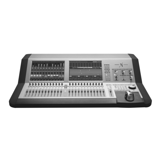
- Page 3 Thank you for choosing a Mackie Digital X Bus for your next-generation digital recording con- sole. The Digital X Bus offers you the fl exibility to confi gure it for virtually any recording application through its extended card cage and I/O routing op- tions.
- Page 4 DB25 standard, you can use a DB25-to-DB25 audio cable. Otherwise, you will need to use DB25 cables that breakout to XLR, 1/4" TRS, or TT connectors. Refer to Appendix B in the Digital X Bus X.200 Owner's Manual for a wiring diagram of these connectors.
-
Page 5: Digital Card
4. DIGITAL CARD This card provides eight channels of digital I/O in two formats; TDIF on a DB25 connector and ADAT optical on four TOSLINK connectors. At 44.1/48 kHz sample rates, each optical TOSLINK connector provides either eight inputs or eight outputs of digital audio. - Page 6 The Sync card provides the digital word clock in and out on a pair of BNC connectors, and SMPTE time code in and out on a pair of 1/4" jacks. Sync data is also transmitted through the ADAT lightpipe and AES/EBU connections. The Sync card just provides another means to transmit and receive the word clock.
- Page 7 This one is self-explanatory. When the POWER switch is turned ON, power is supplied to the Digital X Bus and it boots up. When turning off the Digital X Bus, you should select Shutdown from the File menu. At the end of the shutdown procedure, the touchscreens go blank, indicating that it is okay to turn off the power switch.
-
Page 8: Digital Trim
The MIDI bank is used to convert the Digital X Bus into a control surface for any DAW that supports the Mackie Control Universal protocol. You can select the DAW you are using from an emulation mode box to confi gure the MIDI bank to work with your particular DAW via the MIDI IN/OUT connectors. - Page 9 The following procedure demonstrates how to connect a microphone to an input and get sound out of the Digital X Bus. Here’s what you’ll need: • 1 stereo power amplifi er • 1 pair of monitor speakers (you can substi- tute a pair of powered monitors for the power amplifi...
- Page 10 9. Connect the Left and Right Speaker Outs (A) from the Mix Out card to the inputs of your ste- reo power amplifi er (or powered monitor speak- ers). These outputs are balanced when using a TRS (tip-ring-sleeve) connector, or unbalanced when using a TS (tip-sleeve) connector.
- Page 11 21. In the Reverb panel, click the Src L drop-down box and select Channel Post Insert > Ch. 1 Post. This places the reverb in the post-insert loop on channel 1. 22. Adjust the reverb parameters using the V-Pots at the bottom of the Effects Rack. You should see the Left Input and Output meters move as you talk or sing into the microphone.
- Page 12 One of the primary applications for the X.200 is multitrack recording. This involves tracking and monitoring, bouncing, overdubbing, and mixdown. A typical application might involve 24 inputs for tracking and 24 outputs to a multitrack recorder or DAW (Digital Audio Workstation). In this case, you might have three MIC/LINE 4 CARDS installed in slots 1-3 (A•SLOTS) for 24 analog inputs, and three...
- Page 16 16220 Wood-Red Road NE • Woodinville, WA 98072 • USA www.mackie.com • sales@mackie.com United States and Canada: 800.898.3211 Fax: 425.487.4337 Europe, Asia, Central and South America: 425.487.4333 Middle East and Africa: 31.20.654.4000...