
Related Manuals for Lowrance PRO X51


Summary of Contents for Lowrance PRO X51
- Page 1 Pub. 988-0151-59A X51 Pro Fish-finding & Depth Sounding Sonar Installation and Operation Instructions...
- Page 2 Copyright © 2008 Navico, Inc. All rights reserved. Lowrance is a registered trademark of Navico, Inc. ® Marine-Tex™ is a trademark of Illinois Tool Works Inc. Lowrance Electronics may find it necessary to change or end our policies, regulations, and special offers at any time. We reserve the right to do so without notice.
-
Page 3: Table Of Contents
Capabilities and Specifications: X51 Pro ... 2 Section1: Installation... 3 Installation Preparations... 3 Transducer Installation ... 3 Transom Transducer Assembly and Mounting ... 7 Trolling Motor Bracket Installation... 10 Transducer Orientation and Fish Arches... 12 Shoot-Thru Hull Preparation ... 12 Power and Cable Connections ... -
Page 4: Capabilities And Specifications: X51 Pro
Capabilities and Specifications: X51 Pro Case size:... 5.8" H x 4.3" W x 2.5" D (14.7 cm H x 10.8 cm Display: ...High-contrast Film SuperTwist LCD. Resolution:... 168 pixels (vert.) x 132 pixels (horiz.) resolution; Backlighting: ...Backlit screen and keypad for night use. Input power: ...10 to 15 volts DC. -
Page 5: Section1: Installation
Section 1: Installation Thank you for buying a Lowrance sonar designed for both professional and novice fishermen. All Lowrance sonars have an automatic mode that finds and displays the bottom, fish, underwater structure and more – right out of the box. All you have to do is press the on ( NOTICE! The storage and operation temperature range for your unit is from... - Page 6 installation methods is right for your boat. Use extreme care if mounting the transducer inside the hull, because once it is epoxied into position, the transducer usually cannot be removed. Remember, the transducer installation is the most critical part of a sonar installation! Your Skimmer transducer typically comes packaged with a one-piece stainless steel bracket for mounting it to the transom of your boat.
- Page 7 NOTE: Some aluminum boats with strakes or ribs on the outside of the hull create large amounts of turbulence at high speed. These boats typically have large outboard motors capable of propelling the boat at speeds faster than 35 mph. Typically, a good transom location on aluminum boats is between the ribs closest to the engine.
- Page 8 How low should you go? For most situations, you should install your Skimmer transducer so that its centerline is level with the bottom of the boat hull. This will usually give you the best combination of smooth water flow and protection from bangs and bumps.
-
Page 9: Transom Transducer Assembly And Mounting
However, the shoot-thru-hull installation does have its drawbacks. First, some loss of sensitivity does occur, even on the best hulls. This varies from hull to hull, even from different installations on the same hull. This is caused by differences in hull lay-up and construction. Second, the transducer angle cannot be adjusted for the best fish arches on your sonar display. - Page 10 If the transducer's face isn't parallel with the ground, remove the transducer and ratchets from the bracket. Place the ratchets into the holes in the bracket with the letter "B" aligned with the dot stamped in the bracket. Reassemble the transducer and bracket and place them against the transom.
- Page 11 Mark the center of each slot for the mounting screw pilot holes. You will drill one hole in the center of each slot. Drill the holes using the #29 bit (for the #10 screws). Transom Position transducer mount on transom and mark mounting holes. Side view shown at left and seen from above at right.
-
Page 12: Trolling Motor Bracket Installation
Flat-bottom hull Align transducer centerline with hull bottom and attach to transom. 6. Route the transducer cable through or over the transom to the sonar unit. Make sure to leave some slack in the cable at the transducer. If possible, route the transducer cable away from other wiring on the boat. - Page 13 Bolt Attach motor mounting bracket to transducer. 2. Slide the adjustable strap supplied with the TMB-S through the slot in the transducer bracket and wrap it around the trolling motor. Position the transducer to aim straight down when the motor is in the water.
-
Page 14: Transducer Orientation And Fish Arches
Transducer Orientation and Fish Arches If you do not get good fish arches on your display, it could be because the transducer is not parallel with the ground when the boat is at rest in the water or at slow trolling speeds. If the arch slopes up –... - Page 15 hours, fill the remaining space with polyester resin. When the job is finished, the hull is watertight and structurally sound. Remember, the sonar signal must pass through solid fiberglass. Any air bubbles in the fiberglass or the epoxy will reduce or eliminate the sonar signals. Transducer location (high speed) Shoot-thru-hull transducer locations for...
- Page 16 If you can't get an acceptable bottom signal, try turning up the sensitivity by three or five keystrokes and then move the transducer around once more. If you find a spot that works, mark it and move on to step 4. If you have to turn up sensitivity by more than five keystrokes to get a good signal, the transducer should be mounted on the outside of the hull.
- Page 17 100 grit sandpaper. The sanded hull area should be about 1-1/2 times the diameter of the transducer. The surface of the hull must be flat so the entire transducer face is in contact with the hull prior to bonding. After sanding, clean the hull and transducer with rubbing alcohol to remove any sanding debris.
-
Page 18: Power And Cable Connections
the transducer should be parallel with the hull, with a minimum amount of epoxy between the hull and transducer. 4. Apply a weight, such as a brick, to hold the transducer in place while the epoxy cures. Be careful not to bump the transducer while the epoxy is wet. -
Page 19: Mounting The Sonar Unit (Bracket And Portable)
To unit Power and transducer connections for the X51 Pro sonar unit (direct battery connection shown). CAUTION: Do not use this product without a 3-amp fuse wired into the power cable! Failure to use a 3-amp fuse will void your warranty. This unit has reverse polarity protection. - Page 20 Bracket Installation Mount the unit in any convenient location, provided there is clearance when it’s tilted for the best viewing angle. You should also make sure there is enough room behind the unit to attach the power/transducer cable. (See the following drawings, which show the dimensions of a mounted X51 Pro.) Holes in the bracket’s base allow wood screw or through-bolt mounting.
- Page 21 slack for tilting and turning the unit and attaching the connector. (The snug fit of the push-on waterproof connector requires some force to attach.) Align the bracket over the cable hole with the cable slots facing away from you and fit the cable through the slots. Fasten the bracket to the dash using the two screw holes.
-
Page 22: Portable Transducer Assembly
Installing the Batteries Release the latch on the front of the case. Open the case and install eight AA batteries in the battery compartment. After installing the batteries, plug the sonar unit's power cable into the battery compartment socket. Route the other end of the cable through the opening under the mounting bracket and close the case. -
Page 23: Section 2: Operation
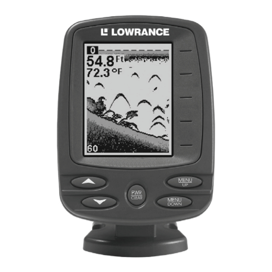
Section 2: Operation Keyboard Numbers in the following photo correspond to the following key explanations: X51 Pro 1. PWR/CLEAR This key appears in the manual text simply as . Press this key to turn the unit on and off. It also clears menu selections and the menus from the screen. -
Page 24: Menus
Menus The menu keys access these features, allowing you to customize the unit to your particular needs and water conditions. All you have to do to leave one menu and enter another is press the menus, simply press the screen. Menus change depending on the mode the unit is in. -
Page 25: Chart Scroll
Chart Scroll In normal operation, the sonar chart will scroll from right to left across the screen. You can stop the chart from scrolling across the screen. This is useful when you want to "freeze" the picture to study it more closely. To stop the chart, press DOWN ARROW stationary "Stop"... -
Page 26: Depth Range Zoom
Depth Range Zoom When turned on, the unit automatically adjusts the depth range according to water conditions. When in auto range mode, it always keeps the bottom displayed in the lower portion of the screen. You can over-ride the automatic depth range control and manually select a depth range. -
Page 27: Sensitivity
When you Zoom while the unit is in manual depth Range Zoom mode, you can select one of 13 pre-set Zoom Sizes. This lets you enlarge some other particular segment of the water column. Zoom Size menu with the 5-15 foot zoom selected. The boat is in 28 feet of water, but the screen has zoomed in on the water column from 5 to Sensitivity Sensitivity controls the unit's ability to pick up echoes. -
Page 28: Grayline
To adjust Sensitivity, press menu appears. Press DOWN ARROW press NOTE: If you want to change the sensitivity in Manual Mode, first turn off Auto Sensitivity: press until the ENSITIVITY Press DOWN ARROW clear the menu. To adjust the sensitivity, follow the same steps used for adjusting sensitivity in auto mode above. -
Page 29: Fish I.d
Fish I.D .™ The Fish I.D. feature displays fish symbols in place of the actual fish echoes. There are three symbol sizes: small, medium and large. Fish arches At left, underwater scene in normal fish arch mode. Right, Fish I.D. Fish I.D. -
Page 30: Chart Scroll Speed
To turn it on, press to select ARROW RACK above steps, but press off FishTrack depths but leave Fish I.D. on, press select , then press use the FishTrack feature. Chart Scroll Speed The rate that echoes scroll across the screen is called the chart scroll speed. -
Page 31: Depth Alarms
To turn off the fish alarm without turning off fish symbols, press until DOWN LARM press to clear the menu. Repeat the above steps to turn the alarm back on, but press UP ARROW Depth Alarms The depth alarms are triggered only by the bottom signal. No other echoes will activate these alarms. -
Page 32: Backlight
Backlight The display is backlit for night use. To turn the backlight on or off, press appears. Press to turn it off. ARROW Display Contrast To adjust the contrast, press ONTRAST DOWN ARROW screen contrast. The bar graph in the Contrast menu box shows a graph of the contrast. -
Page 33: Simulator
Simulator This unit has a built-in simulator that shows a simulated bottom signal with fish signals. This lets you practice with the unit as if you were on the water; all features and functions of the unit are usable. To use the simulator, press menu appears. -
Page 34: Index
Accessories, 18 Alarms, 28 Fish Alarm, 28, 29 Antenna, 35 ASP (Advanced Signal Processing), 13, 28 Backlights / Lighting, 2, 30 Batteries, 3, 16, 17, 19, 20, 30, 33, 34, 35 Contrast, 2, 30 Depth Alarms, 29 Depth Range, 3, 13, 14, 24, 25, 34 Fish Alarm, 28, 29 Fish Depths, 27 FishTrack™, 27... -
Page 35: Troubleshooting
Troubleshooting Unit won't turn on: 1. Check the power cable's connection at the unit. Also check the wiring. 2. Make certain the power cable is wired properly. The red wire connects to the positive battery terminal, black to negative or ground. 3. - Page 36 Bottom echo disappears at high speeds or erratic digital reading or weak bottom echo while boat is moving 1. The transducer may be in turbulent water. It must be mounted in a smooth flow of water for the sonar to work at all boat speeds. 2.
- Page 37 NAVICO FULL ONE-YEAR WARRANTY "We," "our," or "us" refers to NAVICO, INC., the manufacturer of this product. "You" or "your" refers to the first person who purchases this product as a consumer item for personal, family or household use. We warrant this product against defects or malfunctions in materials and workmanship, and against failure to conform to this product's written specifications, all for one (1) year from the date of original purchase by you.
- Page 38 How to Obtain Service… …in the USA: We back your investment in quality products with quick, expert service and genuine Lowrance parts. If you're in the United States and you have technical, return or repair questions, please contact the Factory Customer Service Department.
- Page 39 Accessory Ordering Information for all countries To order Lowrance accessories such as power cables or transducers, please contact: 1) Your local marine dealer or consumer electronics store. Most quality dealers that handle marine electronic equipment or other consumer electronics should be able to assist you with these items. To locate a Lowrance dealer near you, visit our web site, www.lowrance.com and look for the Dealer Locator.
- Page 40 Visit our web site: Lowrance Pub. 988-0151-59A © Copyright 2008 All Rights Reserved Printed in USA 042908 Navico...