Table of Contents
Advertisement
Advertisement
Table of Contents

Related Manuals for Lowrance X-4 Pro


Summary of Contents for Lowrance X-4 Pro
- Page 1 X-4 Pro Fish-Finding Sonar Installation and Operation Instructions...
- Page 2 Navico. Any unauthorized commercial distribution of this manual is strictly prohibited. Lowrance is a registered trademark of Navico. ® Navico may find it necessary to change or end our policies, regulations, and special offers at any time.
-
Page 3: Table Of Contents
Table of Contents Capabilities and Specifications: X-4 Pro ........1 Preparations ..................2 Installation ................... 2 Recommended Tools and supplies ........... 3 Selecting a Transducer Location ............. 3 How low should you go? ..............5 Shoot-Thru-Hull vs. Transom Mounting ........5 Transom Transducer Assembly and Mounting ...... - Page 4 Noise Rejection and ASP™ ..............37 Depth Display ..................39 Temperature Display ................. 39 Voltage ....................40 Backlight ..................... 40 Contrast ....................40 Simulator .................... 40 Set Language ..................41 Software Information ................. 41 Reset Options..................41 Troubleshooting ................42...
-
Page 5: Capabilities And Specifications: X-4 Pro
Capabilities and Specifications: X-4 Pro General Case size: ......5.8" H x 4.3" W x 2.5" D (14.7 cm H x 10.8 cm W x 6.6 cm D) sealed, waterproof; suitable for saltwater use. Display: ......High-contrast Film SuperTwist LCD. Di- agonal viewing area: 4"... -
Page 6: Preparations
NOTICE! The storage temperature for your unit is from -4 degrees to +167 degrees Fahrenheit (-20 degrees to +75 degrees Celsius). Extended storage in temperatures higher or lower than specified will damage the liquid crystal display in your unit. This type of damage is not covered by the warranty. -
Page 7: Recommended Tools And Supplies
Depending on your sonar unit's connectors, your transducer cable may also have the sonar unit's power cable attached to it. If that is the case, be sure to install the transducer first, before connecting the power cable to a power source. See the instructions later in this manual for connect- ing the power cable to a battery or other power supply. - Page 8 NOTE: Some aluminum boats with strakes or ribs on the outside of the hull create large amounts of turbulence at high speed. These boats typically have large outboard motors capable of propelling the boat at speeds faster than 35 mph. Typically, a good transom location on aluminum boats is between the ribs closest to the engine.
-
Page 9: How Low Should You Go
How low should you go? For most situations, you should install your Skimmer transducer so that its centerline is level with the bottom of the boat hull. This will usually give you the best combination of smooth water flow and protec- tion from bangs and bumps. -
Page 10: Transom Transducer Assembly And Mounting
varies from hull to hull, even from different installations on the same hull. This is caused by differences in hull lay-up and construction. Second, the transducer angle cannot be adjusted for the best fish arches. This can be a problem on hulls that sit with the bow high when at rest or at slow trolling speeds. - Page 11 Reassemble the transducer and bracket and place them against the transom. Again, check to see if you can move the transducer so it's pa- rallel with the ground. If you can, then go to step 3. If it doesn't, repeat step 2, but use a different alignment letter.
- Page 12 Transom Transom Position transducer mount on transom and mark mounting holes. Side view shown at left and seen from above at right. 5. Attaching transducer to transom. Remove the transducer from the bracket and re-assemble it with the cable passing through the bracket over the bolt as shown in the following figures.
- Page 13 Bottom hull Deep-"vee" hull Flat-bottom hull Align transducer centerline with hull bottom and attach to transom. 6. Route the transducer cable through or over the transom to the sonar unit. Make sure you leave some slack in the cable at the transducer.
-
Page 14: Trolling Motor Bracket Installation
Trolling Motor Bracket Installation 1. Attach the optional TMB-S bracket to the transducer as shown in the following figure, using the hardware supplied with the transducer. (Note: The internal tooth washer is supplied with the TMB-S.) TMB-S bracket Internal tooth washer Bolt Flat washer Attach motor mounting bracket to transducer. -
Page 15: Transducer Orientation And Fish Arches
Transducer Orientation and Fish Arches If you do not get good fish arches on your display, it could be because the transducer is not parallel with the ground when the boat is at rest in the water or at slow trolling speeds. Partial fish arches Transducer aimed Transducer aimed... - Page 16 ers. The sonar signal must pass through solid fiberglass. A successful transducer installation can be made on hulls with flotation materials (such as plywood, balsa wood or foam) between layers of fiberglass if the material is removed from the chosen area. See the figure below. WARNING: Do not remove any material from your inner hull unless you know the hull's composition.
-
Page 17: Testing Determines Best Location
Testing Determines Best Location Ideally, the shoot-thru transducer should be installed as close to the transom as possible, close to the centerline. This will give you the best performance during high speed maneuvers. 1. Anchor the boat in about 30 feet of water. Add a little water to the sump of the boat. -
Page 18: Shoot-Thru-Hull Installation
hull. This is especially true if you have to turn sensitivity all the way up to get a decent bottom signal. 4. Most people can get good results by following steps 1 through 3, so this step is optional. If you want to make an extra effort to be absolutely sure that your selected location will work under all conditions, make a test run with the boat on plane and observe the bottom signal. -
Page 19: Power Connections (Permanent Mount Only)
2. The epoxy consists of the epoxy itself and a hardener. Remove the two compounds from the package and place them on the paper plate. Thoroughly stir the two compounds together until the mixture has a uniform color and consistency. Do not mix too fast or bubbles will form in the epoxy. -
Page 20: Mounting The Sonar Unit: In-Dash, Bracket Or Portable
This unit can be installed in a dash with the optional FM-6 in- dash adapter kit. The FM-6 kit includes an instruction sheet, part 988- 0147-631, which contains a template for cutting out the mounting hole. This document can be downloaded free from www.lowrance.com. -
Page 21: Bracket Installation
[2.77] Front view (left) and side view (right) showing dimensions of the X-4 Pro when mounted on quick release bracket. Drill a 1" (25.4 mm) hole in the dash for the power/transducer and ac- cessory cables. The best location for this hole is immediately under the gimbal bracket location. - Page 22 Screw hole Power/transducer cable Cable slot X-4 Pro quick release mounting bracket. Slots in the base allow routing the cable from beneath the mount. Attach the unit to the bracket by first connecting the power/transducer and accessory cables. Then, hold the sonar unit vertically and slide it onto the bracket from above.
-
Page 23: Portable Sonar Installation
Portable Sonar Installation Like many Lowrance products, the X-4 Pro is capable of portable opera- tion. It uses the optional PPP-12 portable power pack. The power pack and portable transducers expand the uses for your sonar. -
Page 24: Installing The Batteries
Plug in the power/transducer cable and you're ready to fish. The PPP- 12 has a quick-release mounting bracket built into the case. Installing the Batteries Open the case and lay it flat. (The latch is located below the handle.) Insert eight "AA" size batteries into the battery adapter and place it in the battery compartment. -
Page 25: Portable Transducer Assembly
Ratchet To mount the sonar, slide the unit onto the bracket from above (left). To adjust the view, press and release spring-loaded ratchets while tilt- ing the unit (right). To adjust the viewing angle, pinch the quick-release mount's ratchets with one hand, then tilt the unit with your other hand. Release the rat- chets and the unit locks into the new position. - Page 26 Make sure there is one washer on each side of the transducer, inside the bracket. Slide the other washer over the end of the bolt and screw on the nut. Screw the suction cup onto the bracket using the supplied screw and flat washer.
-
Page 27: Portable Transducer Storage
Hull Portable transducer installed on boat transom. Portable Transducer Storage There is room inside the power pack for the portable transducer. When you're finished fishing, tilt the sonar down to the storage position. Open the case and lay it flat. Unplug the power connector from the battery compartment socket. -
Page 28: Operation
↓ (DOWN) ↑ (UP) this manual. You will use these keys to adjust most features and functions on the X-4 Pro. Memory This unit has permanent memory that saves the following user settings when power is turned off: Units of Measure, Temp Size, Depth Size, Fish I.D. -
Page 29: Display
keys access these features, allowing you to customize unit set- MENU tings. To switch menus, press repeatedly. Press to clear menus MENU from the screen. The Backlight menu with backlight turned on. Display The lights will flash for about 10 seconds when the unit is turned on. The backlight menu will appear on the screen. -
Page 30: Full Chart
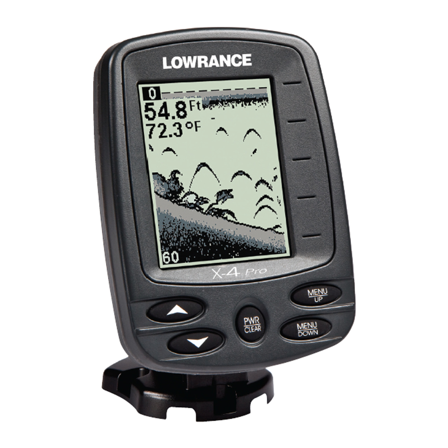
Full Chart The unit's default page, Full Chart shows all echoes scrolling across the full screen. The bottom signal scrolls across the screen from right to left. The line at the top of the screen represents the surface. The bottom depth —... -
Page 31: Zoom
Depth Range menu with Manual setting selected (left). Range Size menu with 0-80 ft highlighted (right). Zoom The zoom feature enlarges all images on the screen by doubling the size of the echoes (a 2X zoom). For example, if the current auto depth range is 0 to 60 feet, Zoom will show an enlarged view of the water column from 30 feet to 60 feet, always keeping the bottom in view. -
Page 32: Sensitivity
To turn off the zoom feature, repeatedly press until the menu MENU appears. Press ↑ to select , then press to clear the menu. The top of the depth range scale returns to zero. NOTE: Using the Zoom command while in auto Zoom mode will always en- large the echoes near the bottom, because auto Range always keeps the bottom displayed in the lower portion of the screen. - Page 33 Sensitivity set to manual mode (left). Sensitivity scroll bar (right). You can change the sensitivity level whether you are in Auto Sensitivity mode or Manual Sensitivity mode. The adjustment method works the same in both modes, but gives you slightly different results. To adjust sensitivity in Auto Mode: Repeatedly press until the...
-
Page 34: Grayline
Fish arches These figures show results of different sensitivity levels on the same location. Fig. 1: Sensitivity at 98 percent, determined by Auto Sensitiv- ity. Typical of full auto mode. Fig. 2: Sensitivity set at 71 percent. Fig. 3: Sensitivity set at 47 percent. Fig. 4: Sensitivity set at 100 percent. ®... -
Page 35: Chart Speed
is usually adequate for most conditions. Experiment with your unit to find the Grayline setting that's best for you. To change the Grayline level, repeatedly press until the MENU RAYLINE scroll bar appears. Wider ® Thin or no Grayline ® Grayline A small amount of Grayline indicates a soft bottom (left), probably sand or mud. -
Page 36: Frequency
better images as you decrease the chart speed to match the speed of your boat. If you are at anchor, ice fishing or fishing from a dock, experiment with a chart speed of 25 percent. If you are drifting slowly, try a chart speed of 50 percent. -
Page 37: Fish I.d
Fish I.D.™ The Fish I.D.™ feature displays — as fish — targets that meet certain conditions. The microcomputer analyzes all echoes and eliminates sur- face clutter, thermoclines and other undesirable signals. The Fish I.D. feature displays symbols on the screen in place of the ac- tual fish echoes. -
Page 38: Fishtrack
Fish I.D. mode and without to become more familiar with the feature. This unit's default Fish I.D. setting is on. Fish I.D. is most handy when you are in another part of the boat or per- forming some task that prevents you from watching the sonar screen. Then, you can turn on Fish I.D. -
Page 39: Depth Alarms
To turn on Fish I.D., repeatedly press until the menu ap- MENU pears. Press to select , then press . Repeatedly press ↓ MENU til the menu appears. Press to select , then press ↑ LARM To turn off fish alarm repeatedly press until the menu MENU... -
Page 40: Deep Alarm
Press . The Shallow Alarm Value dialog box will appear. ↓ ALUE Use ↑ ↓ to enter the first number in the dialog box, then press MENU to move to the next digit. Repeat those steps until the desired DOWN depth has been entered in the dialog box. -
Page 41: Battery Alarm
Battery Alarm To set the battery alarm depth, repeatedly press until MENU ATTERY appears. LARM Battery Alarm menu (left). Low Battery Alarm Value (right). Press the . The Low Battery Alarm Value dialog box will ↓ ALUE appear. Input a voltage value between 7 and 18 volts. Use the keys ↑... - Page 42 Noise Rejection menu. The ASP noise rejection feature is especially useful because, typically, it lets you operate the boat at all speeds without adjusting the sensitiv- ity or other controls. The ASP feature has three settings — Off, Low and High. When first turned on, noise rejection is set on low.
-
Page 43: Depth Display
Depth Display Depth may be displayed on the screen in a small, medium or large size or can be turned off completely. To display Depth: Repeatedly press until the menu appears. Use to select ↑ ↓ MENU EPTH the size of the depth display. Press to clear the menu. -
Page 44: Voltage
Voltage The Voltage menu allows you to display battery voltage on the screen in a small or medium size or can be turned off completely. To display battery voltage: Repeatedly press until the menu appears. Use to se- ↑ ↓ MENU OLTAGE lect the size of the voltage display. -
Page 45: Set Language
Simulator menu (left). Languages menu (right). To use the simulator, repeatedly press until the menu MENU IMULATOR appears. Press to turn it on and press to clear the menu. Repeat ↑ the steps above to turn it off. The simulator automatically will be turned off when you power off the unit. -
Page 46: Troubleshooting
Troubleshooting If your unit is not working, or if you need technical help, please use the following troubleshooting section before contacting the factory custom- er service department. It may save you the trouble of returning your unit for repair. For contact information, refer to the last page, just in- side the back cover of this manual. - Page 47 3. The water may be deeper than the sonar's ability to find the bottom. If the sonar can't find the bottom signal while it's in the automatic mode, the digital sonar display will flash continuously. It may change the range to limits far greater than the water you are in.
- Page 48 vere cases, it can completely cover the screen with black dots, or cause the unit operate erratically, or not at all. To eliminate or minimize the effects of electrical noise, first try to de- termine the cause. With the boat at rest in the water, the first thing you should do is turn all electrical equipment on the boat off.
- Page 49 Notes...
-
Page 50: How To Obtain Service
800-324-1354 8 a.m. to 5 p.m. Central Standard Time, M-F Lowrance Electronics may find it necessary to change or end our ship- ping policies, regulations, and special offers at any time. We reserve the right to do so without notice. -
Page 51: Accessory Ordering Information
Accessory Ordering Information for all countries To order Lowrance GPS accessories such as computer cables or MMC cards, please contact: 1) Your local marine dealer or consumer electronics store. Most quality dealers that handle marine electronic equipment or other consumer electronics should be able to assist you with these items. - Page 52 Visit our web site: www.lowrance.com *988-10015-001*...