
Related Manuals for FUTABA 9z


Summary of Contents for FUTABA 9z
- Page 1 CONTENT UPDATE OVER 80 PAGES OF INFORMATION THE UNOFFICIAL WORKSHOP MANUAL Version 3 Release 5 by QuinCross July 2012 © 2012 jamesandtracy.co.uk www.jamesandtracy.co.uk...
- Page 2 René Berger, from Germany - for improving this version by pointing out the current “glitches”. Crazy8’s from RCGroups who paved the way in replacing the 9Z’s soft button covers. WARNING: THE INFORMATION IN THIS MANUAL IS FOR INFORMATION PURPOSES ONLY AND MAY BE INCORRECT, CAUSE DAMAGE TO YOUR RADIO OR INJURY TO YOURSELF AND OTHERS.
-
Page 3: Table Of Contents
1.3. Disclaimer & Warning! ..................8 1.4. Distribution and Use ................... 9 1.5. How to Report Errors and Get the Most Recent Version ........9 1.6. The Different Futaba 9Z Models ............... 10 2. How to use this Manual ................... 13 ... - Page 4 The Futaba Service and Test Menu ................ 73 6.1. Overview ......................73 6.2. How to Access and Use these Menus on the 9Z ..........73 6.3. Service Menus (Calibration and Upgrade) ............75 6.4. Test Menus (Fault Finding & Checking) ............76 ...
- Page 5 Figure 21 The three LCD Button Panels shown on a 9ZHP WC2 ........28 Figure 22 Allen head bolt at the bottom of the 9Z aerial (3/32" or 3mm head) ....29 Figure 23 The access hole for the aerial retaining bolt in the battery compartment ..30 ...
- Page 6 Figure 33 Access holes for hard resetting a 9Z .............. 39 Figure 34 Changing the Rotational Position of Joysticks ..........40 Figure 35 Crack in the base of a 9Z joystick adding significant play to the control ..41 Figure 36 Metal joystick strengthening collet ..............42 ...
-
Page 7: List Of Tables
Figure 73 Ribbon cables with masking tape fed back through case ....... 71 Figure 74 Cables at sides of LCD Panel that get trapped ..........72 Figure 75 Overview Flowchart for Futaba 9Z Service and Test Menus ......74 Figure 76 Futaba 9Z Service Menus Flowchart .............. 75 ... -
Page 8: Introduction
Finally, there are some people I need to thank. There is a lot of information on the web about the 9z and other Futaba radios. Before I got hold of my 9Z radio and serviced it there were many others who blazed the trail for me. Without these RC adventurers out there living (and sometimes blowing up!) the dream, this document would never have come about. -
Page 9: Distribution And Use
9ZAP WC2 (aka 9ZAW II). You can damage your radio, yourself and others, so please ensure you read the following: This is not an authorized Futaba document and the author is not employed by Futaba. The author is a private individual and the information contained in this document has been assembled from numerous sources and through direct experimentation;... -
Page 10: The Different Futaba 9Z Models
1.6. The Different Futaba 9Z Models There are 3 main versions of the Futaba 9Z each available in two flavours (Aircraft and Helicopter). The three main versions comprise: The original 9Z – 9ZAP is the aircraft version and 9ZHP the helicopter. -
Page 11: Figure 2 The First Version Of The Futaba 9Z
Figure 2 The First Version of the Futaba 9Z The original 9Z is shown in Figure 2 above. Notice the differences when compared to other 9Z models: The unique PCM1024Z logo between the two dials on the front face and the unique button text and colouring around the LCD. -
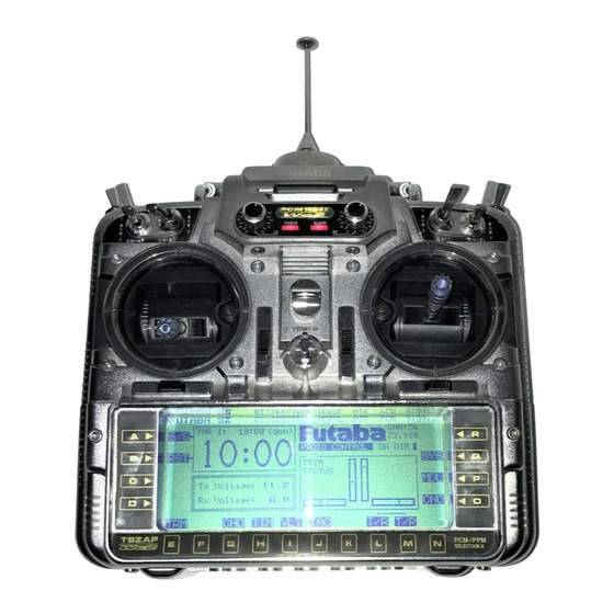
Page 12: Figure 3 The Futaba 9Zaw, The Second Version Of The 9Z (Aka The 9Z Wc1)
Figure 3 The Futaba 9ZAW, the second version of the 9Z (aka the 9Z WC1) The 9Z WC1 is shown in Figure 3 above. Notice that the differences are in the same areas as before: the PCM1024Z logo and the buttons around the LCD. -
Page 13: How To Use This Manual
For example, having found the procedure you need in this section, you’d then read the detailed process for it in Section 3 (Servicing the 9Z). This procedure would refer you out to other areas of the document when required; e.g. -
Page 14: Servicing And Upgrade Matrix
You can use the following tables to navigate this manual, solve specific issues or fix faults with your 9Z. Table 1 shows some common faults and issues and the possible ID of the solution in Table 2. Table 2 below provides a matrix of the service and upgrade procedures detailed in this manual, the tools required to perform them and the level of difficulty (refer to the key below the table for an explanation of the symbols). - Page 15 Tailoring the Reference Plane of Joysticks Strengthening and repairing the Joysticks Backlit LCD Display 4.5 9Z Mode and Version Change (e.g. ZAP to ZHP) Upgrading to 2.4GHz and Telemetry Cycling and Fast Charging the Transmitter Battery Pack ...
-
Page 16: Preparation And Tools
THE UNOFFICIAL WORKSHOP MANUAL FUTABA 9Z Building your own PC interface for backing up the 9Z Building a Training Cable for Buddy Boxing 4.10 Adding a 10 Channel to the 9Z 4.11 APPENDIX Building your own Futaba Service Menu Enabler *Key for “Difficulty”... -
Page 17: Specific Tools
THE UNOFFICIAL WORKSHOP MANUAL FUTABA 9Z Figure 6 General Tools Required 2.3.2. Specific Tools I would really suggest you invest in a solder pump (blue syringe in Figure 7) and a variable temperature soldering iron (Blue soldering iron with dial in Figure 7) for any work involving Printed Circuit Boards. -
Page 18: Working With Printed Circuit Boards (Pcbs)
THE UNOFFICIAL WORKSHOP MANUAL FUTABA 9Z If you intend to build your own CAMPAC for the 9Z and have a general interest in building other electronic RC gadgets then you’ll need a PIC programmer (see Figure 8). This is a piece of kit that can upload code that you’ve either written yourself or have downloaded from the internet to a PIC MicroChip. -
Page 19: Soldering
9Z sub-case and it will provide a permanent earth, but I don’t have (or use) one and so far everything has been fine. -
Page 20: Servicing The 9Z
3. SERVICING THE 9Z 3.1. User Password If you have forgotten the user password for your 9Z you can use the Service and Test Menu to display the password, instead of having to reset it through a hard reset of the transmitter. -
Page 21: Front Face Controls, Gimbals, And Pots
3.4. Front face controls, gimbals, and POTs Note: I have not replaced the Front Face Controls so this procedure may be incomplete. Disassemble the 9Z’s case to Stage 2 as described in Section 5 (Disassembling and Reassembling the 9Z’s Case). -
Page 22: Figure 10 Removing The Main Pcb
THE UNOFFICIAL WORKSHOP MANUAL FUTABA 9Z Figure 10 Removing the main PCB Figure 11 Lever up the PCB - Note: Metal Ratchet on Throttle at Right WARNING: THE INFORMATION IN THIS MANUAL IS FOR INFORMATION PURPOSES ONLY AND MAY BE INCORRECT, CAUSE DAMAGE TO YOUR RADIO OR INJURY TO YOURSELF AND OTHERS. -
Page 23: Replacing The Joysticks And Potentiometers (Pots)
3.4.2. Replacing the Joysticks and Potentiometers (POTS) The joysticks on the 9Z weaken over time and can crack, whilst you can repair them using the procedure in Section 3.4, they are easy to replace at the same time as you service the complete 9Z gimbal assembly (inc. - Page 24 There are two sorts used on the 9Z series of transmitters – one is blue and one is silver. Futaba can provide exact replacements or you can find the little numbers written on the POTS and plug this into Google to find an aftermarket replacement.
-
Page 25: Figure 14 Joystick Gimbal Removed (Note: New Joystick Parts For Replacement On The Right)
THE UNOFFICIAL WORKSHOP MANUAL FUTABA 9Z Figure 14 Joystick gimbal removed (Note: new joystick parts for replacement on the right) Figure 15 Disassemble the horizontal axis POT and joystick (new joystick parts in 1 & 6) WARNING: THE INFORMATION IN THIS MANUAL IS FOR INFORMATION PURPOSES ONLY AND MAY BE INCORRECT, CAUSE DAMAGE TO YOUR RADIO OR INJURY TO YOURSELF AND OTHERS. -
Page 26: Figure 16 Unscrew The Ball Bearing From The Horizontal Axis Pot
THE UNOFFICIAL WORKSHOP MANUAL FUTABA 9Z Figure 16 Unscrew the ball bearing from the horizontal axis POT Figure 17 Slice the heat-shrink tubing and desolder the POT WARNING: THE INFORMATION IN THIS MANUAL IS FOR INFORMATION PURPOSES ONLY AND MAY BE INCORRECT, CAUSE DAMAGE TO YOUR RADIO OR INJURY TO YOURSELF AND OTHERS. -
Page 27: Figure 18 Assembling A New Joystick (Note: Diy Strengthening Collet Modification)
THE UNOFFICIAL WORKSHOP MANUAL FUTABA 9Z Figure 18 Assembling a new joystick (note: DIY strengthening collet modification) Figure 19 Remove the vertical axis POT retaining plates and withdraw the POT WARNING: THE INFORMATION IN THIS MANUAL IS FOR INFORMATION PURPOSES ONLY AND MAY BE INCORRECT, CAUSE DAMAGE TO YOUR RADIO OR INJURY TO YOURSELF AND OTHERS. -
Page 28: Replacement Of Lcd Button Panels
Figure 20 Desolder the connector PCB (green) from the POT 3.5. Replacement of LCD button panels The 9Z transmitter, like its predecessor the 9V, uses software buttons that are activated by clicking the corresponding button on the LCD button panel. However, unlike the 9V, these button panels are manufactured as self adhesive units (see Figure 21) and it is common for these panels to become worn and fail over the life of the transmitter. -
Page 29: 35Mhz Aerial Replacement And Servicing
‘ball joint’ at the top of the transmitter case (see Figure 22). Figure 22 Allen head bolt at the bottom of the 9Z aerial (3/32" or 3mm head) WARNING: THE INFORMATION IN THIS MANUAL IS FOR INFORMATION PURPOSES ONLY AND MAY BE INCORRECT, CAUSE DAMAGE TO YOUR RADIO OR INJURY TO YOURSELF AND OTHERS. -
Page 30: Backup (Lithium) Battery
When this happens a warning message (BACK UP) will be displayed on the LCD and the 9Z will emit an alarm tone that you cannot cancel. Replacement of this battery is not difficult, but you really will need the right tools (refer to Section 2.3). -
Page 31: Figure 24 Label And Protect The New Battery
Make sure you have the tools to access the Service and Test Menu ready (see Section 6.2) Backup your settings for your 9Z onto a CAMPAC 64 or Ultrapac 64 as they will be wiped by the battery replacement process. -
Page 32: Figure 25 Removing The Top Pcb Of The Lcd Assembly
THE UNOFFICIAL WORKSHOP MANUAL FUTABA 9Z Figure 25 Removing the top PCB of the LCD Assembly Figure 26 Top PCB 'Flipped' and Battery Terminals Exposed Desolder and remove the old battery terminals using your iron and pump, being careful to note which terminal is +ve and which is –ve (see Figure 26) Double check you are going to place your new battery the right way round and, once you are sure, solder it in. -
Page 33: Cleaning The Lcd Screen
LCD’s PCB assembly. Make sure you are earthed and protect your tools so you don’t damage ribbon cables etc., again see Section 2.3. Disassemble the 9Z’s case to Stage 4 as described in Section 5 (Disassembling and Reassembling the 9Z’s Case). -
Page 34: Replacing The Lcd Screen
Section 2.3. Whilst it is possible to replace a cracked or damaged 9Z LCD screen, the cost is usually prohibitive as Futaba charge $100’s for the replacement part. This usually means that it is cheaper to buy a replacement transmitter or live with the damage. -
Page 35: Transmitter Battery Pack
Section 4.7. The 9Z’s transmitter battery pack is somewhat different from the usual transmitter packs you can buy readily from the internet or your local model shop. It is a cartridge style pack with an in-built PCB and 0.1”... -
Page 36: Figure 30 Blown Schottky Diode On Mini Pcb
1 x 400mA Schottky diode, 1 x 0.1” receptacle and 1 x standard charge socket) There are two common things that happen with 9Z battery packs that require servicing: The NiCad battery becomes exhausted and needs to be replaced. -
Page 37: Rf Module
Futaba), to all intents and purposes these seem to be interchangeable for PPM operation and a Futaba agent even confirms this in one positing. Certainly, I have used both TK and TP variants in my 8u’s, 9c’s, 9VAP and 9ZAP without issues for PPM operation. -
Page 38: Hard Resetting The 9Z Back To Factory Settings
Note: I have not tested this procedure myself, but there is a lot of information on the internet suggesting that the following will hard reset a 9Z. You will need to access the Futaba Service Menu which requires a Service Menu Enabler (see Section 6) Whilst removing the back-up battery in a 9Z will hard reset the transmitter, there is an easier way to return your set to factory defaults without disassembling it. -
Page 39: Figure 33 Access Holes For Hard Resetting A 9Z
THE UNOFFICIAL WORKSHOP MANUAL FUTABA 9Z Disassemble the 9Z’s case to Stage 1 as described in Section 5 (Disassembling and Reassembling the 9Z’s Case). Open the now empty battery compartment and locate the two access holes shown in Figure 33. -
Page 40: Upgrading And Tailoring The 9Z
THE UNOFFICIAL WORKSHOP MANUAL FUTABA 9Z 4. UPGRADING AND TAILORING THE 9Z 4.1. Adding extra 3 position switches You can upgrade your 9ZAP WC2 into a hybrid 9ZAP/ZHP for glider or helicopter flying by changing the existing 2 position Switch E into a 3 position switch. Equally well you can add extra 3 position switches to a 9ZAP or 9ZAP WC1 and upgrade it to WC2 status. -
Page 41: Strengthening And Repairing The Joysticks
(see Figure 35). As an older set, the 9Z appears to be particularly susceptible to this sort of damage through fatigue. As fatigue damage occurs spontaneously, you should periodically inspect your joysticks for cracks. -
Page 42: Figure 36 Metal Joystick Strengthening Collet
THE UNOFFICIAL WORKSHOP MANUAL FUTABA 9Z suggest you fit collets to your joysticks regardless of whether you have a current crack – they will really help prevent one occurring. If you do fit a collet, for whatever reason, remember to continue to periodically check for play in the joystick as the collet will “hide”... -
Page 43: Backlit Lcd Display
I have thought hard and I won’t be doing it, even though it looks cool! You need to come to your own conclusions. Figure 38 A Backlit 9Z using the 'EL Panel' solution Figure 39 Wiring in the EL Panel, voltage regulator and switch You will need to source and purchase a suitable inverter and an EL Panel. -
Page 44: 9Z Mode And Version Change (E.g. Zap To Zhp)
I would attempt it lightly. The 9Z can have its stick mode and default version (helicopter or aircraft) changed through the modification of a resistor on the main PCB (see Figure 41). However, an WARNING: THE INFORMATION IN THIS MANUAL IS FOR INFORMATION PURPOSES ONLY AND MAY BE INCORRECT, CAUSE DAMAGE TO YOUR RADIO OR INJURY TO YOURSELF AND OTHERS. -
Page 45: Upgrading To 2.4Ghz And Telemetry
9ZAP, this is complex and beyond the scope of this manual. However, a simple solution exists. It is suggested that you refer to the 9Z operation manual and emulate this behavior using the 9Z software mixes and the existing 9Z toggle switches. -
Page 46: Important: Antenna Positioning For Maximum Range
For “plug-and-play” simplicity, choose Corona or Assan. Although I really rate the Corona set (which I have used for the last 5 years), others have had issues with the 9Z. As a result, think about the Assan offering which most people like with the 9Z. -
Page 47: Upgrading To 2.4Ghz Using The Frsky Dht-U
Although the DHT-U comes with everything you need to connect it to the 9Z transmitter at the RF Module port, the proposed solution by FrSky is visually messy and spoils what is otherwise an excellent 2.4GHz solution. As supplied the DHT-U has... -
Page 48: Figure 43 The Dht-U Upgrade With Connections Through Diy Rf Module
Figure 44 and Figure 44: Purchase a FrSky Futaba compatible RF module case, they’re about £3. You can purchase special 0.1” extended PCB headers for the connectors, but these are difficult to come by, so you can also use a standard 5 pin x 2 rows 0.1”... -
Page 49: Figure 44 Modified Rf Module For An Frsky Dht-U
Connect up the appropriate pins on the IDC socket to those on the 3 pin header and once complete, glue the PCB with the header on it into position. Assemble the RF Module and test the fit in the back of the 9Z’s case. Fit the 3 pin ‘receptacle’ onto the correct lines of the DHT-U. -
Page 50: Upgrading To 2.4Ghz Using The Spektrum Dm8 Module
As a result the connection can be very easily damaged, especially if the set is knocked over as it extends far enough to hold the set off the ground when the 9Z is laid on its back (see Figure 46). This is dangerous as a model could well be lost as a result of a loose connection caused by such damage. -
Page 51: Cycling And Fast Charging The Transmitter Battery Pack
1/2C of the original pack or 1/5C of a modern pack). For all these reasons it’s a very good idea to upgrade the 9Z’s battery pack with a bigger diode and build you a simple diode jumper. The total cost will be about £2. If you always use the jumper for fast charging, the larger diode is not really needed. -
Page 52: Figure 47 The 9Z Transmitter Pack Diode Jumper
SOLDER 0.1" HEADER STEP 3 – The finished jumper Figure 47 The 9Z transmitter pack diode jumper To upgrade the original battery cartridge’s 400mA diode to a more bullet proof version follow the procedure below: Purchase a 3Amp Schottky diode rated at 20V or higher Open up the battery case by unscrewing the retaining screws. -
Page 53: Figure 48 9Z Transmitter Battery Disassembly
THE UNOFFICIAL WORKSHOP MANUAL FUTABA 9Z Figure 48 9Z Transmitter Battery Disassembly Figure 49 400mA diode on the mini PCB WARNING: THE INFORMATION IN THIS MANUAL IS FOR INFORMATION PURPOSES ONLY AND MAY BE INCORRECT, CAUSE DAMAGE TO YOUR RADIO OR INJURY TO YOURSELF AND OTHERS. IF YOU USE THIS MANUAL YOU DO SO SOLEY AT YOUR OWN RISK. -
Page 54: Building A Dsc Cable For Direct Servo Control
CAMPACs come in different sizes – 16K, 64K, 128K and 256K. Unfortunately only 64K and larger CAMPACs will work with the 9Z. This is annoying as the only simple-to-make WARNING: THE INFORMATION IN THIS MANUAL IS FOR INFORMATION PURPOSES ONLY AND MAY BE INCORRECT, CAUSE DAMAGE TO YOUR RADIO OR INJURY TO YOURSELF AND OTHERS. -
Page 55: Building A Training Cable For Buddy Boxing
CAMPACs. Therefore, if you are going to build your own CAMPAC for the Futaba 9Z you’ll need a PIC programmer (~£9 for a Chinese clone). Actually programming the PIC chip and making up the circuit is simple, but the cost of the programmer normally means it is not worth it unless you are going to programme other projects. -
Page 56: Futaba 10Z Upgrade - Adding A
4.11. Futaba 10Z upgrade - Adding a 10 Channel to the 9Z Note: This has only been tested on a 9Z WC, but will probably hold true for the WC2 and earlier 9Z model. The 9Z WC transmits a hidden 10th channel by default. Channel 10 is non-proportional (just like Channel 9) and is permanently assigned to switch-D. -
Page 57: Disassembling And Reassembling The 9Z's Case
You can be confident that this is not the case; these ‘difficulties’ seem to have arisen because of the 9Z’s “Puzzle Box” case. Having completely disassembled my own 9Z, I can say that as long as you are relatively competent at ‘household’... -
Page 58: Figure 53 Overview Of 9Z Case Disassembly
Servicing and Upgrade Matrix in Section 2.2. FURTHER DISASSEMBLY IS POSSIBLE & SOMETIMES REQUIRED: The stages detailed in this manual only deal with the 9Z’s case. For many procedures you’ll also need to disassemble a PCB board, these procedures are detailed at the relevant Servicing or Upgrade section in this manual. -
Page 59: Stage 1 - Module And Battery
5.1. Stage 1 – Module and Battery Stage 1 Disassembly: Open the battery hatch and slide out the 9Z’s transmitter battery back. Pull on the ribbon that slides under the battery to remove it safely without bending any battery pins. -
Page 60: Figure 55 Removing The Comfort Grips
Remove the case bottom cover Warning: Do not skip this step. Failure to remove the bottom cover is one of the primary reasons why people find reassembling the 9Z case back such a nightmare! Figure 56 Removing the bottom cover WARNING: THE INFORMATION IN THIS MANUAL IS FOR INFORMATION PURPOSES ONLY AND MAY BE INCORRECT, CAUSE DAMAGE TO YOUR RADIO OR INJURY TO YOURSELF AND OTHERS. -
Page 61: Figure 57 Loosen These Screws On Top Cover
This and failure to remove the bottom cover are the primary reasons why people find reassembling the 9Z case back such a nightmare! Figure 57 Loosen these screws on top cover Undo the case back retaining screws and carefully lever up the cover from the bottom. -
Page 62: Figure 58 Lever Up Back Cover
THE UNOFFICIAL WORKSHOP MANUAL FUTABA 9Z Figure 58 Lever up back cover As depicted in Figure 59, label all ribbon cables on the main PCB that is now exposed. You should know where and how to refit each and every one so take a photo with a camera. -
Page 63: Figure 60 Screws To Loosen To Allow Play In Case Sides
Once the case back is in place replace its screws. Warning: Do not pull up on the carrying handle of the 9Z as recommended by some posters on the internet. The carrying handle is attached to the 9Z metal case frame not the top panel and will just bend the whole 9Z out of alignment. -
Page 64: Figure 61 Protect A Screwdriver And Lever Case Top Up To Refit Case Back
THE UNOFFICIAL WORKSHOP MANUAL FUTABA 9Z Figure 61 Protect a screwdriver and lever case top up to refit case back Refit the battery hatch by sliding it under the bottom edge of the back cover (see Figure 62). You’ll need to lever the back cover up a little to do this. Once complete you can refit and tighten the back cover screws. -
Page 65: Stage 3 - Case Sides And Corner Switches
THE UNOFFICIAL WORKSHOP MANUAL FUTABA 9Z Fit the case bottom cover Retighten the case sides if you loosened them and check that the top corner covers are pushed back into the right position before tightening. Retighten the top cover screws This completes Stage 2 reassembly 5.3. -
Page 66: Figure 64 Case Corner Removed And Ribbons Detached
THE UNOFFICIAL WORKSHOP MANUAL FUTABA 9Z Figure 64 Case corner removed and ribbons detached Take a photo of the ribbon cables for the corner covers – you need to know which one fits which socket (see Figure 64). Figure 65 Case sides slid outwards and removed Stage 3 disassembly is complete when both sides and corners have been removed (see Figure 64 &... -
Page 67: Stage 4 - Lcd Panel
THE UNOFFICIAL WORKSHOP MANUAL FUTABA 9Z Stage 3 Reassembly: Complete in reverse order to disassembly. Fit the side(s) being careful not to trap ribbon cables, but do not tighten the retaining Allen key screws. “Snap-Slide” the corner covers into place. The corners first “snap” into place by pushing them down, and then you slide them forward into position (see Figure 66). -
Page 68: Figure 67 - Partial Step 3 Disassembly Option
THE UNOFFICIAL WORKSHOP MANUAL FUTABA 9Z Figure 67 - Partial Step 3 Disassembly Option Stage 4 Disassembly Label all ribbon cables on the main PCB if you have not already done so. You should know where and how to replace each and every one so take a photo with a camera. -
Page 69: Figure 68 Remove These Cables To Access Lcd Panel
THE UNOFFICIAL WORKSHOP MANUAL FUTABA 9Z Figure 68 Remove these cables to access LCD panel Turn the transmitter over and remove and loosen the following Allen key screws shown in Figure 69. Figure 69 Remove and loosen these screws (note those already removed in Stage 3, if they... -
Page 70: Figure 70 Lever Up Pcb Panel
THE UNOFFICIAL WORKSHOP MANUAL FUTABA 9Z Figure 70 Lever up PCB panel Once the LCD panel is out you can flip it over backwards, carefully pulling the two ribbon cables you undid in Step 1 through the case. It will still be retained by some ribbon cables so be careful (see Figure 72). -
Page 71: Figure 72 Lcd Panel Flipped Over Backwards For Access
THE UNOFFICIAL WORKSHOP MANUAL FUTABA 9Z Figure 72 LCD Panel flipped over backwards for access This completes Stage 4 disassembly Stage 4 Reassembly Complete in reverse order to disassembly. Feed the two ribbon cables you removed back through the case. Use low tack masking tape to protect them and aid reassembly (see Figure 73). -
Page 72: Figure 74 Cables At Sides Of Lcd Panel That Get Trapped
THE UNOFFICIAL WORKSHOP MANUAL FUTABA 9Z Re fit the LCD panel being very, very careful not to trap any cables (see Figure 74). Warning: There are cables on each side that can become lodged over screw holes in sides of the main cases body. Check for these as you will put a screw through the middle of them if they are missed when you refit the sides. -
Page 73: The Futaba Service And Test Menu
CAMPAC Pins. Intermittent or bad connections have been known (rarely) to brick the 9Z. Option 3 is only a cost effective choice if you already have a need for a new CAMPAC, as a Service Menu Enabler is very easy and cheap to make. -
Page 74: Figure 75 Overview Flowchart For Futaba 9Z Service And Test Menus
Note: if you would like to see an “Easter Egg” personal message from the developers of 9Z go to the voltage screen and press [L] and [M] simultaneously. Once the first message appears you may press [L] and [M] again which brings a second message up. -
Page 75: Service Menus (Calibration And Upgrade)
Do not calibrate the middle position of Switch A if you have a 3 (Switch Calibration) position switch or you will need to hard reset the 9Z transmitter. Neutral calibration process for joysticks (e.g. J1 is Joystick 1 etc.). Neutral Rev Set all sticks to their neutral / centre position before pressing “SET”... -
Page 76: Test Menus (Fault Finding & Checking)
6.4. Test Menus (Fault Finding & Checking) TO SERVICE MENUS This is the toggle switch test. Move all toggle switches on the 9Z case to all positions, the boxes associated with them will Switches become black when test is complete (e.g. SA is Switch A) This is the digital trims test. -
Page 77: Appendix A. The (Almost) Universal Service Menu Enabler
THE UNOFFICIAL WORKSHOP MANUAL FUTABA 9Z APPENDIX A. THE (ALMOST) UNIVERSAL SERVICE MENU ENABLER Compatible with FUTABA 9z, 9c, 10c & 8u Series Designed by Quincross CAMPAC PINOUT This is the Campac pin numbering as you look at the radio... -
Page 78: Appendix B. Connection Port Pin-Out Information
The Pin-Outs described are fairly universal and do not just apply to the Futaba 9Z series. However, on very old transmitters predating the original 9Z you should be careful to check that the information supplied is still applicable. For example, the 9VAP series uses a 7 pin DIN for DSC rather than the 6 pin DIN described in this appendix, whilst the RF Module Pin-Out is laid out in exactly the same format. -
Page 79: B.3. Futaba Dsc/Trainer Pin-Out Information
RF Output Indicator (Pulls to ground when RF is detected) RF Out B.3. Futaba DSC/Trainer Pin-out Information The connector in Figure 80 is a standard 6 pin DIN which is readily available from most audio equipment and electronic component providers... -
Page 80: B.4. Campac Pin-Out Information
Pin 1 = Unknown (see Note below) Note: Be careful not to short this Pin 1! It probably enables/disables write protect on the built in EPROM. This would allow Futaba to put the latest code into a radio without replacing the surface mounted (SIP) EPROM. -
Page 81: Appendix C. Component Part Numbers
Table 5 below provides a list of the key component part numbers used in the procedures detailed in this manual. 9Z Model Component Supplier Part No. Notes Hobby Services (Note: Futaba direct part number in brackets, some suppliers exclude the “Y-“) 9Z WC2 Gimbal / Joystick Futaba HSP73839 ST-22B (R) 9ZAW throttle (Y-TFT1500020) gimbal inc. -
Page 82: Futaba 9Z
THE UNOFFICIAL WORKSHOP MANUAL FUTABA 9Z 9Z WC2 Buttons Label Futaba HSP73856 Left Side 9Z WC2 Futaba 9Z Futaba HSP39007 Very expensive! Display PCB Expect approx (LCD & PCB) $400. Farnell, DigiKey and RS Online (Note: likely to use the same part codes) -
Page 83: Futaba 9Z
THE UNOFFICIAL WORKSHOP MANUAL FUTABA 9Z WARNING: THE INFORMATION IN THIS MANUAL IS FOR INFORMATION PURPOSES ONLY AND MAY BE INCORRECT, CAUSE DAMAGE TO YOUR RADIO OR INJURY TO YOURSELF AND OTHERS. IF YOU USE THIS MANUAL YOU DO SO SOLEY AT YOUR OWN RISK. - Page 84 “It is not the length of life, it is the depth” www.jamesandtracy.co.uk © 2012 jamesandtracy.co.uk...