ARRI ALEXA User Manual
35 format film-style digital camera
Hide thumbs
Also See for ALEXA:
- User manual (186 pages) ,
- Pocket manual (130 pages) ,
- Quick manual (9 pages)

Related Manuals for ARRI ALEXA


Summary of Contents for ARRI ALEXA
- Page 1 User Manual ARRI ALEXA For ALEXA Software Update Packet 5.0 + 5.1 Printed on 26 January, 2012...
- Page 2 The information and intellectual property contained herein is confidential between ARRI and the client and remains the exclusive property of ARRI. If you find any problems in the documentation, please report them to us in writing. ARRI does not warrant that this document is error-free.
-
Page 3: Table Of Contents
Contents Disclaimer Scope ALEXA Images Introduction to ALEXA About This Manual ..............15 Safety Instructions Explanation of Warning Signs and Indications ......16 General Safety Instructions ............16 ... - Page 4 Contents Center Camera Handle CCH-1 ..........32 Side Camera Handle SCH-1 ............ 33 Bridge Plates BP-12/BP-13 ............34 Bridge Plate adapter BPA-1 ............. 35 Wedge Adapter WA-1 + Quick-Release Plate ......36 ...
- Page 5 12.4 Syncing the Sensors of Two Cameras ........114 12.5 Syncing the Settings of Two Cameras ........115 ALEXA Plus 13.1 General Description ............... 118 13.2 Optics ..................119 ...
- Page 6 Plus Camera Controls ............126 ALEXA Studio 14.1 General description ..............132 14.2 ALEXA Studio images ............133 14.3 Optics ..................136 14.3.1 Electronic mirror shutter ............136 ...
-
Page 7: Disclaimer
In no event shall ARRI or its subsidiaries be liable for or have a remedy for recovery of any special, direct, indirect, incidental, or... - Page 8 Disclaimer The ALEXA viewfinder EVF-1 contains proprietary technology owned by Fourth Dimension Displays Limited and licensed by ARRI. This product contains licensed technology from Linotype. Quicktime and Quicktime logo are trademarks or registered trademarks of Apple Computer, Inc., used under license therefrom.
-
Page 9: Scope
About This Manual Scope This instruction manual applies to the following hardware, software and firmware versions: ARRI ALEXA or ARRI ALEXA PLUS camera with ARRI EVF-1 electronic viewfinder Camera software update packet (SUP): EVF-1 software packet: 1.27 ARRI ALEXA STUDIO camera with optical viewfinder or ARRI EVF-1 electronic viewfinder ... -
Page 10: Alexa Images
ALEXA Images ALEXA Images Figure 1: ALEXA right Figure 2: ALEXA left Figure 3: ALEXA top... - Page 11 About This Manual Figure 4: ALEXA bottom Figure 5: ALEXA front Figure 6: ALEXA back...
-
Page 12: Introduction To Alexa
Introduction to ALEXA Introduction to ALEXA ALEXA is a 35 format film-style digital camera made by ARRI, the world leader in professional cinematographic imaging. It combines leading edge digital technology with film camera features that have been refined over more than 90 years of ARRIs history. The result is a camera that allows cinematographers with a film background to shoot digitally without the need for a extensive training. - Page 13 The fan itself is very silent, so the camera noise level is below 20 dB (A)* - this is the same as with ARRI sync-sound film cameras. If the fan noise level starts to increase due to fan aging, the fan can be swapped in a matter of minutes by a trained technician.
- Page 14 Introduction to ALEXA High speed image capture In Regular Speed mode, ALEXA has a frame rate range from 0.75 to 60 fps. By adding a license key for High Speed mode, the frame rate range of the camera can be extended up to 120 fps.
-
Page 15: About This Manual
About This Manual About This Manual It is recommended that all users of the ALEXA camera read the manual front to back prior to the first usage. The manual's structure also provides quick access for reference to experienced users. All directions are given from an operator's point of view. -
Page 16: Safety Instructions
Do not use accessories or attachments that are not recommended by ARRI, as they may cause hazards and invalidate the warranty! Do not attempt to repair any part of the system! Repairs must only be... -
Page 17: Specific Safety Instructions
If the sensor cover glass has been contaminated by solid dirt or grease, special optical cleaning kits should be used for dirt removal under very high care! If the contamination cannot be removed, the camera should be taken to an ARRI service center for cleaning. - Page 18 Safety Instructions THE USE OF METHANOL TO CLEAN OPTICAL SURFACES IS NOT RECOMMENDED! NEVER USE ACETONE TO CLEAN OPTICAL SURFACES! NEVER TRY TO REMOVE THE SENSOR COVER GLASS! DO NOT POINT THE CAMERA INTO DIRECT SUNLIGHT, VERY BRIGHT LIGHT SOURCES, OR HIGH-ENERGY LIGHT SOURCES (e.g.
-
Page 19: General Precautions
Electromagnetic Interference ALEXA meets EC regulations by fulfilling the specifications of the European Directive 2004/108/EC (15th December 2004). This equipment has been tested and found to comply with the limits for a Class A digital device, pursuant to part 15 of the FCC Rules. - Page 20 To reduce the risk of condensation: Find a warmer storage location. Attach the ARRI air-drying cartridge (silica bottle) to the PL-Mount of the camera during storage (NOT during transport!) If camera needs to be stored in a place that is considerably cooler than the location where it will be used, consider keeping the camera powered from a mains unit in addition to using the air-drying cartridge.
-
Page 21: Power Supply
Manipulation of power supplies can result in severe damage to the equipment and humans, including death. ALEXA accepts an input voltage range from 10.5 to 34 V DC. The camera can be powered through the BAT connector or can be equipped with battery adapters accepting V-Lock or Gold Mount batteries. -
Page 22: Bat Connector
Power Supply BAT Connector The BAT connector of ALEXA is a Fischer 2-pin socket located on the bottom back of the camera right side. The socket accepts power cables KC-20S and KC-29S. The cables can either be connected to the mains unit NG 12/26R or to 24V Cine-style batteries with three-pin XLR outputs. -
Page 23: Onboard Batteries
V-Lock batteries are available from a number of manufacturers. Some of these batteries are able to transmit information on their remaining capacity to the camera. ALEXA displays the remaining capacity in percent on the Homescreen of the camera display. For these batteries, the user does not need to set the battery warning level due to the communication of camera and battery. - Page 24 Move the battery upwards and remove it. Figure 8: ALEXA with BAB-V and V-Mount battery Note: Not all V-Lock batteries deliver enough power to supply the camera. We recommend to not use any batteries with a capacity of less than 90 Wh to prevent damage to the battery and unpredictable camera behavior.
-
Page 25: Gold Mount Batteries
Gold Mount is the battery mounting system of Anton Bauer batteries. The batteries transmit information on their remaining capacity to the camera. ALEXA displays the remaining capacity in percent on the Homescreen of the camera display. For Gold Mount batteries, the user does not need to set the battery warning level due to the communication of camera and battery. -
Page 26: Power Outputs
Power Supply damage to the battery and unpredictable camera behavior. Any camera-battery combination should be tested prior to use, especially when accessories are powered through the camera. Power Outputs The camera has three power outputs for accessories, 2x 24 V and 1x 12 V. Figure 10: 24 V outputs (RS) and 12 V output 7.8.1 12 V Accessories... -
Page 27: Installation Of The Camera
Sony SxS PRO card for recording Tripod and Remote Heads Tripod and remote heads used with ALEXA have to provide enough load capacity to support the camera and attached accessories. The table to the right shows the camera weight for different components. -
Page 28: Electronic Viewfinder Evf-1
Installation of The Camera Viewfinder Cable short KC-150S 0.26 0.12 Center Camera Handle CCH-1 0.60 0.27 Electronic Viewfinder EVF-1 The EVF-1 employs an LCOS imaging device together with a temperature stabilized LED light source to provide an accurate and bright view of the sensor image under all operating conditions. -
Page 29: Viewfinder Cables
Electronic Viewfinder EVF-1 The viewfinder is connected to the camera with the mounting bracket VMB- Figure 11: Camera with EVF-1 Note: Do not point the viewfinder eyepiece at direct sunlight or bright light sources, as this could damage the LCOS imaging device. If possible, cover the eyepiece when not in use to prevent any damage. -
Page 30: Viewfinder Mounting Bracket
Installation of The Camera Figure 12: EVF cables: KC-150S (center), KC-151S (middle), KC-152S (outer) 8.3.2 Viewfinder Mounting Bracket The viewfinder mounting bracket VMB-1 / VMB-2 is attached to the camera with two 3mm Allen screws at the very front of the camera top. The viewfinder is attached to the mounting bracket by sliding the dove tail into the receptacle of the mounting bracket and then closing the lever on the viewfinder. - Page 31 EVF further back. It can be attached to a tripod head for use with geared heads or greater comfort when using fluid heads. The VEB-1 has a standard attachment point for the ARRI eyepiece leveler EL-3. When using the VEB-1 with an eyepiece leveler, loosening the friction where the VEB-1 and the VMB-1 / VMB-2 are joined is critical as tiliting can the damage the friction setting.
-
Page 32: Center Camera Handle Cch-1
Installation of The Camera Center Camera Handle CCH-1 The Center Camera Handle CCH-1 is attached to the camera top with 3 screws, two at the front and one at the back. Make sure the screws are well tightened with a 3mm Allen key. Figure 16: Camera with CCH-1, side view... -
Page 33: Side Camera Handle Sch-1
Side Camera Handle SCH-1 The handle extension block HEB-2 mounts to the front end of the CCH-1 and adds one more focus hook to the camera in a high position, so the tape measure clears the matte box. Side Camera Handle SCH-1 The SCH-1 is used in conjunction with a BAT-V or BAT-G battery top mounting adapter, or with third-party onboard recorders. -
Page 34: Bridge Plates Bp-12/Bp-13
Bridge Plates BP-12/BP-13 The bridge plate BP-12 for 19 mm studio rods has been newly developed for ALEXA. It mounts directly to the camera housing with two screws and ensures that support rods, matte boxes and follow focus units are positioned properly in regards to the optical center of the camera, just like all other ARRI cameras. -
Page 35: Bridge Plate Adapter Bpa-1
The bridge plate adapter BPA-1 can be used to attach a BP-3/BP-5/BP- 8/BP-9 to ALEXA. First attach the BPA-1 to the camera with the two screws. Then attach the bridge plate to the adaptor with its two screws. Make sure... -
Page 36: Wedge Adapter Wa-1 + Quick-Release Plate
Figure 19: ARRI QR-HD-1 Leveling Block LB-1 The leveling block LB-1 attaches to the bottom of the ALEXA back foot. It prevents the camera from resting on a back mounted battery when a bridge plate is attached and the camera is placed on a flat surface. -
Page 37: Shoulder Pad Sp-3
Shoulder Pad SP-3 8.10 Shoulder Pad SP-3 The camera base has an integrated arch to fit to the operator's shoulder. For extended handheld shoots, the newly designed shoulder pad SP-3 can be attached to the base of the camera with velcro. Note: The SP-3 can only be used with a BP-12 and 19 mm rods or with 15 mm rods and a WA-1+quick-release base plate. -
Page 38: Connectors
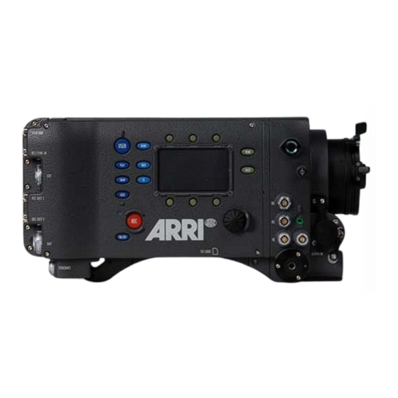
Connectors Connectors Camera back Figure 23: Connectors at back From top to bottom: MON OUT, RET/SYNC IN, EXT, REC OUT 1&2, BAT, ETHERNET Camera right Figure 24: Connectors on right side From left to right, top to bottom: 2x RS (24 V) out, AUDIO OUT, TC, 12V out, AUDIO IN, SD CARD (camera bottom) - Page 39 Shoulder Pad SP-3 Camera left Figure 25: Camera left: SxS slots Top to bottom: SxS slot 1, SxS slot 2 Camera front Figure 26: Camera front connector EVF connector...
-
Page 40: Bat
Connectors The BAT connector can be used to power the camera from an external power source with cables KC-20S and KC-29S. It is located on the camera back lower right. REC OUT 1 + 2 The REC OUT consists of two BNC plugs capable of carrying 1920x1080 1.5G or 3G HD-SDI signals with frame rates from 23.976 to 60 fps according to SMPTE standards 274M, 292M, 372M and 425M. -
Page 41: Ethernet
ARRI (model KC-153-S), is required to connect the Ethernet socket to a standard RJ-45 Ethernet socket. The ethernet port can be used to operate two ALEXA cameras with synced settings by connecting the cameras with cable KC 156-S, or to connect and RCU-4 to the camera. -
Page 42: Audio Out
Connectors 9.10 12 V The 12 V connector supplies an external accessory with 12 V power and up to 2.2 A current. It is located on the camera right lower front. 9.11 The TC connector is a 5pin LEMO socket. It accepts and distributes LTC (Longitudinal Time Code) signals. -
Page 43: Sxs Slots
SxS Slots On the SD card, the folder structure presented in the following example should be created by the user prior to first use of the card. Figure 27: Folder structure required for SD card An unformatted SD card can be formatted with the camera. Go to MENU>System>SD card>Format + prepare SD card. - Page 44 Card is unreadable (e.g. wrong file system) Card is inactive Solid green Card is selected and ready Solid red Card is accessed (read/write) !DO NOT REMOVE CARD! Only Sony SxS PRO cards can be used with ALEXA. Sony SxS-1 cards are not supported.
-
Page 45: Optics
10.1 Lens Adapter PL Mount LA-PL-1 (no LDS) The lens adapter LA-PL-1 is the standard lens mount delivered with ALEXA. It can be used to attach any modern PL-mount lens to the camera. Attaching a lens to the camera ... -
Page 46: Lens Support
Optics Figure 28: PL mount LA-PL-1 with index pin 10.2 Lens Support Heavy lenses may require additional lens support. This guarantees that the flange focal depth is not influenced by the lens weight and reduces stress on the lens mount. To support a lens use 15mm studio or 19mm studio rods and a fitting lens bridge. - Page 47 Lens Support When the bridge is in the right position on the rods, it is fixed with the screw or lever on its side. It is attached to the lens support ring with its center screw. The lever on the back of the lens bridge fixes the height of the center screw.
-
Page 48: Camera Controls
Camera Controls Camera Controls The camera can be controlled through three different interfaces: Main Located on the camera right side. Consist of a 3" LCD-screen controls with screen buttons changing their behavior depending on the screen content, a jogwheel to navigate through menus and adjust parameters and a range of function buttons with dedicated behavior. -
Page 49: Display
Main Controls 11.1.1 Display The LCD display on the right side has a size of 3" and a resolution of 400x240 pixels. The display is back illuminated and transflective which results in exceptional contrast even in bright sunlight. When the Homescreen is displayed, the brightness of the display can quickly be adjusted by turning the jogwheel while pressing the BACK button. - Page 50 5.0-358.0°. Shutter Angle and sensor fps determine exposure time of the sensor in seconds by the following equation: Angle/(360*Fps). Currently set exposure index rated in ASA. ALEXA has a base sensitivity of 800 ASA, the camera rating can be adjusted from 160-3200 ASA.
- Page 51 Apple ProRes, the codec family used for image encoding in ALEXA, is a variable bit rate codec, so the available recording time depends on the image content. It can well be that the available recording time exceeds the value displayed here.
-
Page 52: Lists And User Lists
Sensor is in tropical mode (=40° C mode sensor temperature). Radio WRS radio is active (ALEXA Plus only) Note: A sensor temperature warning or error after bootup is normal until the sensor has reached its preset temperature. 11.1.3.1 Lists and User Lists... - Page 53 Main Controls Select a list value Figure 32: Sensor fps list To select a list value, turn the jogwheel until the selection bar is on the desired value and press the jogwheel. Add a list value If the list lacks the required setting, press the ADD screen button. This opens a screen where the desired value can be set.
-
Page 54: Fps
Camera Controls 11.1.3.2 Pressing the FPS screen button opens the FPS list screen. It contains the default frame rates 23.976, 24.000, 25.000, 29.970, 30.000, 48.000, 50.000, 59.940 and 60.000 fps. Figure 33: Sensor fps list Note: Access to this screen is disabled during record. The maximum fps value that can be set is determined by the maximum frame rate recordable by the SxS PRO card in use. - Page 55 Main Controls Setting sensor fps through REC OUT fps If the sensor fps is linked to the REC OUT frame rate, a message appears instead of the list. While this setting is active, sensor fps can only be changed by changing the REC OUT frame rate. To change this setting, access the REC OUT menu screen (MENU>Recording>REC OUT) and set "REC OUT fps sets sensor fps"...
- Page 56 Camera Controls To prevent this, the camera can mark the duplicate frames with a Variflag. If the recorder supports Variflag recording, it will discard the duplicate frames and only record the active frames. This saves valuable storage space and worktime. To activate the Variflag in the camera, go to Menu>Recording>REC OUT>Variflag.
-
Page 57: Audio
Main Controls The High Speed mode is exited the same way it is loaded, by pressing the upper middle screen button of the FPS list screen. Exiting High Speed mode takes approximately 40 seconds. 11.1.3.3 AUDIO Pressing the AUDIO screen button in the Home screen opens the Audio screen. - Page 58 Camera Controls Record Sets audio recording On or Off. If audio recording is switched off, no audio is recorded in the QuickTime clips, the HD-SDI contains no audio, and the Audio out is muted, too. Channel 1 level Manual allows the user to manually apply gain to the input signal on channel 1 to reach a correct level.
-
Page 59: Shutter
Audio out level: Choose to determine the level of the audio out channels manually, or set it fix to the maximum output. Note: ALEXA automatically determines the internal signal run time and matches audio and images so they are always in sync. When changing sensor fps or project fps, it may take up to 2 seconds for the camera to resync image and audio signals. - Page 60 Figure 40: Exposure Index screen ALEXA has a basic sensitivity of 800 ASA. This means that the dynamic range is almost evenly distributed above and below neutral grey with very low noise in the dark parts of the image and a very clean and smooth clipping behavior in the bright parts.
- Page 61 Main Controls At high ASA ratings like 1600 ASA, the images behave the opposite way. Noise is increased, which makes it important to judge the dark parts of the image, while the clipping behavior will be even smoother. Figure 41: Exposure Indexes and latitude aboive and below neutral grey Figure 42: Graphical comparison of latitude at different exposure indexes...
-
Page 62: Color
Camera Controls 11.1.3.6 COLOR By pressing the COLOR button all settings related to color management can be accessed. The first screen gives an overview of the color settings of all image paths of the camera. It shows the currently active gamma on EVF, MON OUT, REC OUT and SxS. - Page 63 Main Controls The looks are stored in the camera. Additional looks can be loaded from the SD card. Press the ADD button to see look files stored on the SD card. These look files must be stored on the SD card in a folder named LookFiles. The required folder structure on the SD card can be created under MENU>System>SD card>Prepare SD card.
- Page 64 Look Up Tables. Matching preview LUTs can be generated with the ARRI ALEXA LUT generator on www.arridigital.com. Playback and Look Files Look settings of the camera outputs also apply to any clip during playback, if this clip was recorded in LOG C.
- Page 65 Main Controls White balance and color compensation should be adjusted only with the help of appropriate equipment. This can either be a color meter or a vectorscope together with a calibrated grey card. AUTO WB The camera can also perform an automatic white balance. To do this, press the AUTO WB screen button once.
-
Page 66: Function Buttons
SD card. When storing the image is finished, a new frame can be grabbed. Enters the screen for configuring Time code. Available on ALEXA Plus only, it gives access to the Plus camera functions. PLAY Activates playback on MON OUT and EVF. -
Page 67: Tc (Time Code)
Main Controls 11.1.4.1 TC (Time Code) The TC screen shows the currently set TC. The currently active TC settings are displayed below the TC values. Figure 47: Timecode screen Note: Individual frame values are not shown in the screen, even though they are counted. - Page 68 TC count and continues counting on its own. Due to a highly precise crystal oscillator in ALEXA, the internal counter will count accurately for 8 hours. After that period, the camera has to be resynced to avoid any TC offset.
-
Page 69: Info
Note: Saving a system log is only necessary if the camera is showing unnormal behavior. It can then be sent to the ARRI camera service for analysis. The log is not human-readable and can only be analyzed by the ARRI camera service. - Page 70 Camera Controls VERSION Info Cam serial The serial number of the camera. Cam ID Translation of the camera serial number to Base36, with an additional prefix for 3D applications. Firmware Version number of the currently installed camera SUP (Software Update Packet). EVF serial The serial number of the viewfinder that is attached number...
- Page 71 Main Controls Figure 50: SxS CARDS info screen SYSTEM Info Date Currently set date. Can be set in MENU>SYSTEM>DATE/TIME. Time Currently set time. Can be set in MENU>SYSTEM>DATE/TIME. Fan speed Speed of camera cooling fan in rotations per minute. Sensor Current temperature of image sensor.
-
Page 72: User
Camera Controls MON OUT The rate at which frames are output on the MON frame rate OUT HD-SDI. SxS CARD Maximum frames per second the SxS PRO card in 1 max. fps card slot 1 can record with currently set SxS codec. SxS CARD Maximum frames per second the SxS PRO card in 2 max. - Page 73 Main Controls Assign functions to the buttons by using the jogwheel. Figure 54: Edit User Button assignment For user buttons 1-3, which are also available on the camera left side, the following functions can be assigned: Name description None button has no function MON OUT surround toggles surround view of the MON OUT image on/off...
-
Page 74: Play
Camera Controls Check last clip play last 5 seconds of last clip, then return to live image Circle clip set a clip to Circle clip during recording User buttons 4 and 5 have partially different functions Name description None button has no function MON OUT surround toggles surround view of the MON OUT image on/off... - Page 75 Main Controls Pressing the PLAY button opens the play screen and loads the last clip in pause. Pressing the wheel plays the clip back. pressing the wheel again brings the clip back into pause. Figure 55: Play screen In the play screen the playback actions can be controlled. STEPSIZE Toggles the scrub stepsize between 1 frame and 1 second.
- Page 76 Camera Controls To stop playback and return to the live image, press HOME or BACK. If you press REC, playback is stopped, recording is started and the Home screen is loaded. OPTIONS The OPTIONS screen button opens a list of general playback options. Figure 56: Play options screen Clip end action Determines what happens when the end of a...
-
Page 77: Menu
Main Controls Playback and Look Files Look settings of the camera outputs also apply to any clip during playback, if this clip was recorded in LOG C. A clip recorded in REC 709 or ITU P3 with or without look will be played back "as is", even if the output is set to LOG C. Please note that the currently active look is applied to the clip, not the one that was active at the time of recording. -
Page 78: Recording
Provides access to SxS CARDS and REC OUT parameters. Figure 59: MENU>RECORDING SxS CARDS ALEXA can internally record to Sony SxS PRO cards. The card slots are located on the camera's left side. SxS recording Switches SxS recording on or off. With SxS recording off, power consumption is reduced by 15 W. - Page 79 It is recommended to directly format the card and not to postpone this action. Apple ProResTM codecs The following table gives an overview of the range of ProRes codecs. All these codecs are supported by ALEXA. Name Color Data rate Recording time max.
- Page 80 Camera Controls **The maximum frame rate is also limited by the write speed of the SxS PRO card in use, which might reduce the maximum frame rate below the values given in the table. ProRes 4444 is limited to 40 fps with SxS PRO cards up to 32 GB capacity, and only reaches 60 fps with SxS PRO 64 GB cards .
- Page 81 Main Controls Output range Defines which bit range of the full 10 bit (0- 1023) is used to transmit image data. Legal: Uses values 64-940 for RGB and Y signals, and values 64-960 for CbCr signals. This complies with the SMPTE 274M 8.7.
-
Page 82: Monitoring
30-60 fps recording with ALEXA over HD-SDI Unlike the ARRIFLEX D-21, which used a proprietary mode for recording frame rates between 30-60 fps, ALEXA complies with SMPTE standard 372M in terms of image transmission for 422 1.5G DL and 3G SL formats. - Page 83 Electronic level Increases the sensitivity of the electronic level overlay sensitivity on MON OUT and EVF Note: Available on ALEXA Plus only False color Opens a screen where the color coding of the false index color display option of EVF and MON OUT is explained.
- Page 84 Frame lines are a reference for framing that typically consist of an image frame, a center mark and an aspect ratio reference. See the appendix for more information on the ALEXA frame line format. Surround mask If surround view is set to "On", it must be separated from the recorded image area to allow proper framing.
- Page 85 Electronic level Overlay showing the horizontal levelling of the camera. Only available on ALEXA Plus. LDS info Overlay showing LDS lens info. Only available on ALEXA Plus. MON OUT The MON OUT is a 422 1.5G single link HD-SDI output. The output range is fixed to legal range.
- Page 86 Frame lines are a reference for framing that typically consist of an image frame, a center mark and an aspect ratio reference. See the appendix for more information on the ALEXA frame line format. Surround mask If surround view is set to "On", it must be separated from the recorded image area to allow proper framing.
- Page 87 Frame lines are an image overlay that can be applied to either the EVF image, the MON OUT image, or both. ALEXA frame lines are stored as XML files containing definitions what the frame lines look like. The camera contains default frame lines for 1.33:1, 1.66;1 1.78:1, 1.85:1, 2.39:1, 2.39 1.3x anamorphic and 2.39 2.0x anamorphic aspect ratios.
-
Page 88: Project
Camera Controls Set rect 1 Set the shape of rectangle 1. Activate it through User rectangles. Set rect 2 Set the shape of rectangle 2. Activate it through User rectangles. Note: Default frame lines have "User" specified as color for all content. False Color Index The false color index screens contains a visual reference for the false color mode available for EVF and MON OUT. - Page 89 Main Controls Note: The user should set the value of reel counter to 001 before a shoot begins. Figure 66: MENU>PROJECT Production Info The production info screen contains fields to enter info metadata regarding the production. The user can enter the names of the director, cinematographer, location and production.
-
Page 90: System
Camera Controls Figure 68: Production info edit screen 11.1.5.4 System Contains groups of system settings. Figure 69: MENU>SYSTEM Sensor Sensor When shooting in tropical conditions with high temperature temperature and humidity, the sensor temperature can be changed to "Tropical". This will avoid condensation on the sensor coverglass. - Page 91 Influences naming of clips on SxS cards. Sensor sync The sensors of 2 ALEXA cameras can be synced. See Sensor sync (on page 114) for more info. Off: The camera is in non-synced mode for regular use.
- Page 92 HD outputs of the cameras are synced. Press the jogwheel to send the trigger. Settings sync ALEXA cameras can be operated in synced settings mode, where two cameras sync their settings via Ethernet. See Settings sync (on page 115) for more info.
- Page 93 Main Controls Figure 72: MENU>SYSTEM>DISPLAY System Time + Date Time Shows the currently set time (read-only) Date Shows the currently set date (read-only) Set time + date Opens a screen whre time and date can be set Time zone Set time zone to match your current location Set daylight savings time Set time + date Figure 73: MENU>SYSTEM>CLOCK/DATE...
- Page 94 SD card without touching any data present on the SD card. WNA-1 The Wireless Network Adapter WNA-1 is a new accessory from ARRI that will soon be released and allows to connect a camera to a WLAN network. Firmware The camera firmware can be updated to enable new camera features.
- Page 95 11.1.5.4.1.1 Licensed Features Licensed features are camera functionalities that require a license key to be enabled. Licenses can be purchased through the ARRI ALEXA License webshop, which can be found at http://alshop.arri.de. A detailed instruction on how to purchase a license key can be found on the website.
- Page 96 The license key file (suffix .lic) to be installed must be located on the SD card in the correct folder (folder ARRI >subfolder ALEXA >subfolder Licenses). Note: Only license keys that have been created for the camera in use will appear in the SD card license list.
-
Page 97: Frame Grabs
Main Controls 11.1.5.5 Frame grabs By pressing the GRAB button, or by assigning the function "Grab still frame" to one of the user buttons 1-3, a still image from the sensor can be stored on the SD card. The images inherit the setting of the REC OUT. If it is set to ARRIRAW, frame grabs are currently not posible. -
Page 98: User Setups
Camera Controls Compare mode Interleave creates an interlaced image from the live image and the loaded image. Toggle only displays the laoded image. Active on EVF Sets the compare function on the EVF on or off. Active on MON Sets the compare function on the MON OUT on or off. Note: The image quality on the MON OUT in interleave mode depends strongly on the connected display device. -
Page 99: Operator Controls
Operator controls Note: User setups cannot be used across SUPs. Always create new setup files after a SUP update, and discard the old ones. The camera will block the usage of a user setup that has been created with a different SUP. 11.2 Operator controls The operator controls are located on the camera left side and consist of... -
Page 100: Evf Controls
Camera Controls 11.3 EVF Controls The EVF controls are located on the electronic viewfinder. They consist of a number of function buttons and a jogwheel. Opens the viewfinder CAM menu Opens the viewfinder EVF menu. ZOOM Zooms into the image with a 2.25x magnification for focus checking. -
Page 101: Viewfinder Cam Menu
Frame lines are a reference for framing that typically consist of an image frame, a center cross and an aspect ratio reference. See the appendix for more information on the ALEXA frame line format. Select framelines 1 Choose the main frame lines template from those stored in the camera. -
Page 102: Operation Of The Camera
This chapter contains in formation and recommendations for recording with SxS PRO cards. The user is of course free to modify the recommended worksteps to his needs. Note: ARRI cannot be held responsible for the loss of any data in conjunction with internal recording! - Page 103 Recording ALEXA can internally record on Sony SXS PRO cards. These cards have an ExpressCard34 form factor and are currently available with 8, 16 or 32 GB storage space. Card file format SxS PRO cards have to be formatted in the camera before they can be used for recording.
- Page 104 Operation of The Camera Codec The Apple ProRes codec family consists of 5 different codecs: Name Color Data rate Recording time on max. coding @ 30 fps 32 GB SxS PRO @ frame 30 fps*** rate** ProRes YCbCr 45 Mb/s 1 h 23 min 60 fps 422 (Proxy)
- Page 105 SxS PRO cards have to be formatted in the camera before they can be used for recording. ALEXA uses an UDF file system. This file system is read-only for computers, which means data can be copied from the card to another device, but the data cannot be manipulated on the card itself.
- Page 106 Operation of The Camera File naming scheme ALEXA automatically names files as they are created on the SxS card. While it is possible to change the file names later on a computer, it is not recommended, as the ALEXA naming scheme has been developed to minimize the risk of duplicate file names.
- Page 107 Alternatively, reel name is used sometimes. The tape name of ALEXA files is limited to 8 letters to match the CMX 3600 EDL standard. It consists of the Camera Index, reel counter and the Camera The tape name of the clip from the previous example would then be: A004R1JL.
-
Page 108: External Recording
Operation of The Camera 12.1.2 External recording Uncompressed HD and unprocessed ARRIRAW data is available via the REC OUT for recording with external devices. The preferred output format also depends on the application. As a rule of thumb, the following guideline can be used: ... - Page 109 ARRIRAW is the name of raw data from ARRI cameras. Raw data is the sensor image data before it is converted to RGB images. As ALEXA has a single sensor with a Bayer pattern color filter array, this means that every pixel only has information of one color channel.
-
Page 110: Parallel Recording
Operation of The Camera 12.1.3 Parallel recording Recording to both SxS PRO cards and external devics at the same time requires additional attention from the user. First, it has to be determined what function the two sets of data have. For example, the internal recording could be used for on-set review and proxy editing, while the external device captures the master data. -
Page 111: Monitoring
The different sections in the file are: camera: describes the camera that the frame lines file is made for. As the ALEXA camera system will consist of several cameras in the future, this is necessary to differentiate between the camera types. ... - Page 112 <framelines> <!-- The description of the camera, this will only be used for selecting the correct files. So the user can only select glasses for his camera/current setup. --> <camera> <type>Alexa EV</type> <sensor>3K</sensor> <aspect>1.78</aspect> <hres>2880</hres> <vres>1620</vres> </camera> <!--user color line at top and bottom of 2.35 aspect-->...
-
Page 113: Using Time Code
Using Time Code <color>user</color> </line> <!-- Center cross vertical lines, user color --> <line> <left>0.5</left> <top>0.43519</top> <bottom>0.51543</bottom> <width>4</width> <color>user</color> </line> <line> <left>0.5</left> <top>0.51543</top> <bottom>0.43519</bottom> <width>4</width> <color>user</color> </line> </framelines> 12.3 Using Time Code The purpose of Time code is to ensure that each image stored on one medium has a unique value through which it can be identified. -
Page 114: Syncing The Sensors Of Two Cameras
Operation of The Camera Variations: If the shooting starts close to midnight, the TC might be started with an offset to prevent a rollover at midnight. Restrictions: Only possible if the camera is running at sync-sound speed. If the camera is over- or under-cranking, the TC frame rate will no longer match the sensor frame rate, so that TC values would either be duplicate or dropped. -
Page 115: Syncing The Settings Of Two Cameras
Syncing the Settings of Two Cameras It is possible to operate two ALEXAs with synchronized settings. Camera connection Connect two ALEXAs with the ALEXA Ethernet/Ethernet Cable KC 156-S, or with the ALEXA Ethernet/RJ-45 Cable KC 153-S over an Ethernet hub. Camera setup Go to MENU>SYSTEM>EXT SYNC, and set "Settings sync"... - Page 116 Operation of The Camera The cameras will automatically negotiate IP addresses. After about 5 seconds, connections are established. The master camera will initially distribute its settings to the slave camera. Once this is done, settings can also be changed on the slave camera, and the change will take effect on both cameras.
- Page 117 Syncing the Settings of Two Cameras MENU>Monitoring>EVF>Surround mask MENU>Monitoring>EVF>Framelines MENU>Monitoring>EVF>Anamorphic desqueeze* MENU>Monitoring>MON OUT>Frame rate MENU>Monitoring>MON OUT>Scan format MENU>Monitoring>MON OUT>Status info MENU>Monitoring>MON OUT>Surround view MENU>Monitoring>MON OUT>Surround mask MENU>Monitoring>MON OUT>Framelines MENU>Monitoring>MON OUT>Anamorphic desqueeze* MENU>Project>Project fps In addition, the slave camera takes over the Camera ID of the master camera, so file names are identical except for the Camera ID prefix.
-
Page 118: Alexa Plus
ALEXA Plus ALEXA Plus The ALEXA Plus has an additional set of features compared to the regular ALEXA. Level sensor The level sensor determines the camera's tilt and roll CLM ports Three ports for connecting controlled lens motors. Currently supported motor types are CLM-2 and CLM-3. -
Page 119: Optics
Optics 119 An additional function button labeled WRS. It gives access to the WRS screen, from where all camera setting related to the Plus camera features can be handled. Figure 81: CLM sockets Figure 82: ALEXA Plus connectors 13.2 Optics... -
Page 120: Lens Adapter Pl-Mount La-Pl-2 (With Lds)
13.2.1 Lens Adapter PL-Mount LA-PL-2 (with LDS) The lens mount of the ALEXA Plus supports the ARRI Lens Data System. The LDS lens must be mounted in the 12 o'clock or 3 o'clock position to enable the LDS functions. Take great care not to harm any elements of the LDS contacts on either lens or camera when attaching or deattaching a lens or lens port cover. -
Page 121: Radio System
The ALEXA Plus can be equipped with yellow radio. This radio system has also been in use with ARRI film cameras, so it is an interesting option for rentals that already own equipment with yellow radio. Yellow radio can be identified by a yellow ring at the antenna mount pont. -
Page 122: Wireless Remote System
ALEXA Plus White radio White radio is the standard radio system for the ALEXA Plus. It has 8 available channels. White radio can be identified by a white ring at the antenna mount point. Channel Frequency 2.410 GHZ 2.415 GHZ 2.430 GHZ... - Page 123 3D lens sync When two ALEXA Plus cameras are set Sensor sync EXT master and EXT slave, the slave camera will switch off its radio module and receive motor control commands from the master camera via the EXT connection.
-
Page 124: Hand Units
ALEXA Plus 13.4.2 Hand Units For detailed unformation of the hand units, please refer to the device's own manuals. Wireless Compact Unit WCU-3 The WCU-3 is a compact hand unit featuring a radio system to connect to the camera wirelessly. It has two LCS ports for connecting the device to the camera via cable and to attach a ZMU-3. -
Page 125: Lens Data Display Ldd-Fp
LCS port 1 having priority over LCS port 2. 13.5 Lens Data Display LDD-FP The Lens Data Display for Focus Pullers LDD-FP can be used to display lens information. Connect it to the LDD port of the ALEXA Plus. -
Page 126: Plus Camera Controls
ALEXA Plus 13.6 Plus Camera Controls The ALEXA PLUS has an additional function button labeled WRS. It gives access to the WRS screen, from where all camera settings related to the Plus camera features can be handled. The WRS screen gives an overview of radio status, camera level, LDS status, and CLM status. - Page 127 Plus Camera Controls degrees around 0. Figure 86: Motion sensor reset screen LENS DATA Shows the type of LDS lens connected and the LDS status. The LENS DATA screen button leads to the LDS screen, where lens info like lens type, current focal length, iris, focus distance and close and far point of depth of field are shown.
- Page 128 The LDA consists of a user list and a main archive list. The user list should only contain the lenses currently used to achieve quick access to the desired lens tables. The main archive contains a set of lens tables for ARRI/Zeiss Highspeed, Master Primes and Ultra Primes and can be extended with additional lens tables for any PL-Mount lens.
- Page 129 Plus Camera Controls Custom lens tables can be added to the main archive via the SD card. Place the lens table on the SD card in a folder named "LDA". Insert the SD card into the camera. Go to the main archive list and press ADD. Select the desired lens table and press the wheel.
- Page 130 ALEXA Plus Shows status, direction and torque of the CLM connected to the IRIS socket. Press the IRIS CLM screen button to access the iris CLM screen. This screen shows the type of motor connected to the IRIS socket, its direction and torque.
- Page 131 Plus Camera Controls Shows status, direction and torque of the CLM connected to the FOCUS socket. Press the FOCUS CLM screen button to access the focus CLM screen. This screen shows the type of motor connected to the FOCUS socket, its direction and torque.
-
Page 132: Alexa Studio
ALEXA Studio ALEXA Studio 14.1 General description The ALEXA Studio extends the features of an ALEXA Plus by: Optical viewfinder Brand-new construction from ARRI, featuring optical anamorphic desqueeze, diopter correction, image flip, camera left/right positioning and horizontal distance adjustment ... -
Page 133: Alexa Studio Images
ALEXA Studio images 14.2 ALEXA Studio images Figure 93: ALEXA Studio right Figure 94: ALEXA Studio left... - Page 134 ALEXA Studio Figure 95: ALEXA Studio top Figure 96: ALEXA Studio bottom...
- Page 135 ALEXA Studio images Figure 97: ALEXA Studio front Figure 98: ALEXA Studio back...
-
Page 136: Optics
14.3.2 Lens mount LA-PL-2 (with LDS) The lens mount of the ALEXA Studio supports the ARRI Lens Data System. The LDS lens must be mounted in the 12 o'clock or 3 o'clock position to enable the LDS functions. Take great care not to harm any elements of the LDS contacts on either lens or camera when attaching or deattaching a lens or lens port cover. -
Page 137: Optical Viewfinder
Super16 lenses, or lenses with dimensions not matching the dimensions in the figure "Allowed lens dimensions with mirror shutter" drawing cannot be used with the ALEXA Studio, as they would destroy the rotating mirror shutter! Figure 100: Allowed lens dimensions with mirror shutter 14.3.3... - Page 138 ALEXA Studio Note: To use the optical viewfinder, the mirror shutter must be set to On. The viewfinder is adjustable in two axes, laterally extendable for left eye operation and shows illuminated frame lines (ARRIGLOW). The viewfinder image stays upright and correct left-to-right when the viewfinder is swivelled within the main axis.
- Page 139 Ground glasses contain frame and format markings to show the recorded image area and the area of interest. As the sensor aperture of the ALEXA Studio is different from the camera aperture of ANSI and DIN Super35 formats, only ground glasses made specifically for ARRI digital cameras provide exact format markings.
- Page 140 To remove the field lens, which is located above the ground glass: Remove the ground glass first Screw the ARRI Ground Glass Puller into the field lens Carefully pull out the field lens Figure 104: Field lens in camera with attached Ground Glass Puller...
- Page 141 Optics 141 ARRIGLOW The ARRIGLOW module is integrated in the optical viewfinder system of the ALEXA Studio. It allows illuminated format markings to be superimposed onto the viewfinder image with adjustable brightness. Press the buttons on the left side of the OVF below the DIMMER engravement to adjust the brightness of the ARRIGLOW.
- Page 142 Diopter Adjustment Note: Depends on the eyepiece in use. Description for default eye piece of ALEXA Studio. Turn the eyepiece barrel until the ground glass is in focus. A neutral, unstructured, bright out-of-focus image content helps with this.
- Page 143 Note: The torx screws on the camera that are painted red may not be tightened or loosened, as this would corrupt the alignment of the OVF. Figure 108: OVF with cover plate Figure 109: Alexa Studio with cover plate Swapping the optical viewfinder for an electronic viewfinder EVF-1 ...
-
Page 144: Nd Filter
14.3.4 ND Filter The ALEXA Studio has a ND filter in front of the sensor, which can be be moved in and out of the optical path. The motorized filter slider contains a ND filter with a density of 1.3, and a cover glass without additional density. -
Page 145: Studio Camera Controls
14.4 Studio Camera Controls Only a few additional controls are available on the ALEXA Studio. These are used to control the mirror shutter and the ND filter. The Homescreen has icons for the active ND filter and the mirror shutter position and state. - Page 146 ALEXA Studio In the EI screen, press the lower right screen button labeled ND FILTER to move the ND filter in and out of the optical path. Figure 112: EI screen Mirror shutter activation In the Homescreen, press SHUTTER.
- Page 147 Studio Camera Controls Note: For frame rates higher than 30 fps, it is recommended to use a power source with a voltage level of 18-35 V to ensure the mirror shutter is powered sufficiently! MIRROR PARK buttons VIEW and GATE The camera left side Operator Controls have two additional function buttons labelled VIEW and GATE.
-
Page 148: 4:3 Mode
ALEXA Studio Frame rates higher than 37 fps in 4:3 or 46 fps in 16:9 reduce the maximum possible mirror shutter angle. When the frame rate change reduces the allowed mirror shutter angle below the currently active shutter angle, the camera automatically sets the shutter angle to 135.0°. -
Page 149: Licensed Features
It is possible to switch from 4:3 to High Speed mode and vice versa. In High Speed mode, only the 16:9 center area of the image sensor is read out. 14.6 Licensed features Licensed features High Speed mode and Anamorphic Desqueeze are automatically enabled in the ALEXA Studio. -
Page 150: Rcu-4
RCU-4 RCU-4 Figure 113: RCU-4 remote control unit The camera can be remote controlled with an RCU-4. This device mirrors the controls on the camera's right side. It is connected to the camera's Ethernet port. Power is supplied via the Ethernet cable. To power the RCU-4, press the power button after connecting the device to a camera. -
Page 151: Appendix
Appendix In this appendix Appendix Camera Dimensions Connector Pin Outs False Color Display Infos and Warnings... -
Page 152: Appendix
EI rating 160 - 3200 ASA Recorded image 1920 x 1080 pixels (downscaled from 2880 x resolution 1620) Viewfinder Type ARRI EVF-1 Technology LCOS imaging device Resolution 1280 x 784 pixels Power Power supply DC 11 - 34V Power management... - Page 153 Appendix Appendix 153 Recording media Sony SxS PRO cards Recording Apple ProRes 422/4444 codec family compression codec Frame rates 0.75 - 60 fps 60 - 120 fps in highspeed mode (no Prores 4444) Image Outputs Recording output 2x REC OUT configurable as: 2x 422 1.5G SL YCbCr @ frame rates: 23.976, 24, 25, 29.97 and 30 fps 1x 422 1.5G DL YCbCr @ frame rates:...
- Page 154 20 dB(A) @ 24 fps and ambient temperature < 25° C / 77° F Environmental -20° C to +45° C @ 95% relative humidity max, non condensing ALEXA Plus Length x Width x 332 x 175 x 158 mm Height (body) 12.95" x 6.89" x 6.22"...
- Page 155 Appendix Appendix 155 Total active pixels 3112 x 1782 (incl. surround view) 3112 x 2160 (SUP 5.2 BETA only) Pixels of recorded 2880 x 1620 image 2880 x 2160 (SUP 5.2 BETA only) Aperture of recorded 23.76 x 13.365 mm image 23.76 x 17.82 mm (SUP 5.2 BETA only) Image aperture (incl.
-
Page 156: Camera Dimensions
156 Appendix Camera Dimensions Camera Dimensions All measurements are given in mm. ALEXA Figure 114: ALEXA left Figure 115: ALEXA top... - Page 157 Camera Dimensions Appendix 157 Figure 116: ALEXA bottom Figure 117: ALEXA front and back...
- Page 158 158 Appendix Camera Dimensions ALEXA Plus Figure 118: ALEXA Plus left Figure 119: ALEXA Plus top...
- Page 159 Camera Dimensions Appendix 159 Figure 120: ALEXA Plus bottom Figure 121: ALEXA Plus front and back...
- Page 160 160 Appendix Camera Dimensions ALEXA Studio Figure 122: ALEXA Studio left Figure 123: ALEXA Studio top...
- Page 161 Camera Dimensions Appendix 161 Figure 124: ALEXA Studio bottom Figure 125: ALEXA Studio front and back...
- Page 162 162 Appendix Camera Dimensions...
-
Page 163: Connector Pin Outs
Connector Pin Outs Appendix 163 Connector Pin Outs Note: The drawings of the connectors are not to scale. +24V BAT-COM 24V-AUX... - Page 164 164 Appendix Connector Pin Outs 12V-AUX LTC IN ASCII TUNE OUT LTC OUT...
- Page 165 Connector Pin Outs Appendix 165 RS422-TXD(+) RS232-TXD CAN1-L CAN1-H CAN2-L CAN2-H 24V-AUX RS232-RXD RS422-RXD(-) RS422-RXD(+) RS422-TXD(-) TTL-IN1 TTL-IN2 24V-AUX...
- Page 166 166 Appendix Connector Pin Outs ETHERNET MX-1P MX-1N MX-2P MX-2N MX-3P MX-3N MX-4P MX-4N 24V-ETH AUDIO IN AGND L-IN(+)
- Page 167 Connector Pin Outs Appendix 167 L-IN(-) R-IN(+) R-IN(-) AUDIO OUT R-OUT L-OUT...
-
Page 168: False Color Display
Six different colors are used to show the important luminance ranges. Figure 126: False Color Encoding The following example illustrates the behavior of the false color display. Figure 127: Night scene captured with ALEXA Figure 128: ALEXA night shot with false color active... -
Page 169: Infos And Warnings
Special warnings and errors: Sensor temperature ALEXA has a Peltier element that keeps the image sensor at a stable temperature. This is important to achieve constant image quality. Under some occasions, the camera might not be able to keep this temperature, or it might take some time to reach the correct level. - Page 170 TC source forced to Sensor fps does not match Project fps. internal External Free Run TC cannot be used, camera has switched to Int Rec Run TC. Interface bit error Reboot camera. If error continues to occur, contact ARRI service.
- Page 171 Reboot camera. If error continues to occur, problem contact ARRI service. Internal battery error The internal battery which powers the real-time clock must be replaced. Contact an ARRI service center near you. System problem Reboot the camera. If error continues to occur, contact ARRI service.
-
Page 172: Alexa Error Messages And Meanings
Slave: No lens table With ALEXA Plus and 3D lens sync, select lens active. table on slave when using LDA. REC OUT: Switch on When SxS recording is off and sensor fps does... - Page 173 Fan error. Contact The fan module is not working properly. Either service! install an SFM-1, or contact the ARRI service. Fatal system error! Camera has to be rebooted. If this error Reboot camera now! continues to occur, a hardware problem might be the reason.
-
Page 175: Index
FPS ............... 54 ALEXA Plus ............118 Frame grabs ............97 ALEXA Studio ............. 132 Frame Lines ..........87, 111 ALEXA Studio images ......... 133 Function Buttons ........... 66 Appendix ............. 151, 152 AUDIO ..............57 AUDIO IN .............. 41 AUDIO OUT ............ - Page 176 Index RET/SYNC IN ............40 L RS ................. 41 Lens Adapter PL Mount LA-PL-1 (no LDS) ... 45 Lens Adapter PL-Mount LA-PL-2 (with LDS) ..120 Lens Data Display LDD-FP ......... 125 Lens Motors ............122 S Lens mount LA-PL-2 (with LDS) ......136 Lens Support ............
- Page 177 BUTTON MAP for ARRI ALEXA SUP 5.0 + 5.1 HOME Choose FPS preset from FPS list with jogwheel DELETE Remove a custom fps preset from the list HIGHSPEED Activate highspeed mode (only with installed license) Create a custom fps preset...
- Page 178 Choose exposure index preset from EI list with jogwheel ND FILTER*** Activate ALEXA Studio ND filter COLOR Choose look from look file list SET LOOK with jogwheel DELETE Delete custom look from look file list Add look file from SD...
- Page 179 MENU MENU is covered in a separate graphic. INFO STATUS Shows the current system state SAVE TO SD Save log file to SD card VERSION Shows camera version info SxS CARDS Shows SxS card info SYSTEM Shows system info Shows all frame rates SET TC Set Timecode to desired value SET 2 TIME...
- Page 180 USER Trigger user button 1 Trigger user button 2 Trigger user button 3 Trigger user button 4 Trigger user button 5 EDIT Assign user button functions Button 1 - 3 None / MON OUT surround / MON OUT gamma / MON OUT frame lines / MON OUT status info / MON OUT false color /...
- Page 181 PLAY Play SxS card clips CLIPLIST List of clips on SxS cards OPTIONS Clip end action Pause / Loop Show frame lines On / Off Status info on MON OUT On / Off STEPSIZE 1 frame / 1 second CIRCLE CLIP Yes / No GRAB Grabs image from REC OUT path to SD card.
- Page 182 ARRI ALEXA Plus / ALEXA Studio only: RADIO WRS radio power On / Off WRS radio channel 1 - 8 CAM LEVEL RESET Reset level sensor LENS DATA OPTIONS Focus distance unit Metric / Imperial / Default Unit Circle of confusion 0.013mm /...
- Page 183 Set motor direction left LEFT RIGHT Set motor direction right Increase motor torque Decrease motor torque ALEXA Studio Operator Panel only: GATE Stops spinning mirror shutter. Restarts mirror shutter parked in GATE position Moves mirror shutter parked in VIEW position to GATE. VIEW Stops spinning mirror shutter.
-
Page 184: Menu Map
MENU MAP for ARRI ALEXA SUP 5.0 + 5.1 Recording SxS CARDS SxS Recording On / Off Codec ProRes 422 Proxy / ProRes 422 LT / ProRes 422 LT / ProRes 422 HQ / ProRes 4444 HS codec ProRes 422 Proxy /... - Page 185 Monitoring Electronic viewfinder Brightness 0 - 5 Rotate image On / Off Smooth mode On / Off Surround view On / Off Frame lines + status info > Frame lines On / Off Surround mask Black line / Color line / Mask 25% / Mask 50% / Mask 75%...
- Page 186 Frame lines Frame line 1 Frame lines list choose / add / delete Frame line 2 Frame lines list choose / add / delete User rectangles > User rectangles Off / Rect 1 / Rect 2 / Rect 1 + 2 Set rect 1 set top / bottom / left / right...
- Page 187 System Sensor Sensor temperature Standard / Tropical Mirror image horizontal On / Off Power BAT1(Plug) warning 10.0 - 30.0 V BAT2 (Onboard) warning 10.0 - 30.0 V External sync Eye index L / R Sensor sync Off / EXT master / EXT slave HD out phase -30 - +30 clocks...
- Page 188 SD card Format + prepare SD card Formats SD card + creates required folder structure on SD card Creates required folder Prepare SD card structure on SD card WNA-1 SSID SSID of WNA network For future accessory Firmware Select SUP from SD card Select update file (Current version: Info on installed SUP...
- Page 189 Load setup from SD card Factory reset Reset camera to factory default settings * only on ALEXA Plus ** only with valid Anamorphic desqueeze license key installed or on ALEXA Studio *** only on ALEXA Studio --- End of document ---...